

- •Preface
- •About This Book
- •Acknowledgments
- •Contents at a Glance
- •Contents
- •Relaxing at the Beach
- •Dressing the Scene
- •Animating Motion
- •Rendering the Final Animation
- •Summary
- •The Interface Elements
- •Using the Menus
- •Using the Toolbars
- •Using the Viewports
- •Using the Command Panel
- •Using the Lower Interface Bar Controls
- •Interacting with the Interface
- •Getting Help
- •Summary
- •Understanding 3D Space
- •Using the Viewport Navigation Controls
- •Configuring the Viewports
- •Working with Viewport Backgrounds
- •Summary
- •Working with Max Scene Files
- •Setting File Preferences
- •Importing and Exporting
- •Referencing External Objects
- •Using the File Utilities
- •Accessing File Information
- •Summary
- •Customizing Modify and Utility Panel Buttons
- •Working with Custom Interfaces
- •Configuring Paths
- •Selecting System Units
- •Setting Preferences
- •Summary
- •Creating Primitive Objects
- •Exploring the Primitive Object Types
- •Summary
- •Selecting Objects
- •Setting Object Properties
- •Hiding and Freezing Objects
- •Using Layers
- •Summary
- •Cloning Objects
- •Understanding Cloning Options
- •Mirroring Objects
- •Cloning over Time
- •Spacing Cloned Objects
- •Creating Arrays of Objects
- •Summary
- •Working with Groups
- •Building Assemblies
- •Building Links between Objects
- •Displaying Links and Hierarchies
- •Working with Linked Objects
- •Summary
- •Using the Schematic View Window
- •Working with Hierarchies
- •Setting Schematic View Preferences
- •Using List Views
- •Summary
- •Working with the Transformation Tools
- •Using Pivot Points
- •Using the Align Commands
- •Using Grids
- •Using Snap Options
- •Summary
- •Exploring the Modifier Stack
- •Exploring Modifier Types
- •Summary
- •Exploring the Modeling Types
- •Working with Subobjects
- •Modeling Helpers
- •Summary
- •Drawing in 2D
- •Editing Splines
- •Using Spline Modifiers
- •Summary
- •Creating Editable Mesh and Poly Objects
- •Editing Mesh Objects
- •Editing Poly Objects
- •Using Mesh Editing Modifiers
- •Summary
- •Introducing Patch Grids
- •Editing Patches
- •Using Modifiers on Patch Objects
- •Summary
- •Creating NURBS Curves and Surfaces
- •Editing NURBS
- •Working with NURBS
- •Summary
- •Morphing Objects
- •Creating Conform Objects
- •Creating a ShapeMerge Object
- •Creating a Terrain Object
- •Using the Mesher Object
- •Working with BlobMesh Objects
- •Creating a Scatter Object
- •Creating Connect Objects
- •Modeling with Boolean Objects
- •Creating a Loft Object
- •Summary
- •Understanding the Various Particle Systems
- •Creating a Particle System
- •Using the Spray and Snow Particle Systems
- •Using the Super Spray Particle System
- •Using the Blizzard Particle System
- •Using the PArray Particle System
- •Using the PCloud Particle System
- •Using Particle System Maps
- •Controlling Particles with Particle Flow
- •Summary
- •Understanding Material Properties
- •Working with the Material Editor
- •Using the Material/Map Browser
- •Using the Material/Map Navigator
- •Summary
- •Using the Standard Material
- •Using Shading Types
- •Accessing Other Parameters
- •Using External Tools
- •Summary
- •Using Compound Materials
- •Using Raytrace Materials
- •Using the Matte/Shadow Material
- •Using the DirectX 9 Shader
- •Applying Multiple Materials
- •Material Modifiers
- •Summary
- •Understanding Maps
- •Understanding Material Map Types
- •Using the Maps Rollout
- •Using the Map Path Utility
- •Using Map Instances
- •Summary
- •Mapping Modifiers
- •Using the Unwrap UVW modifier
- •Summary
- •Working with Cameras
- •Setting Camera Parameters
- •Summary
- •Using the Camera Tracker Utility
- •Summary
- •Using Multi-Pass Cameras
- •Creating Multi-Pass Camera Effects
- •Summary
- •Understanding the Basics of Lighting
- •Getting to Know the Light Types
- •Creating and Positioning Light Objects
- •Viewing a Scene from a Light
- •Altering Light Parameters
- •Working with Photometric Lights
- •Using the Sunlight and Daylight Systems
- •Using Volume Lights
- •Summary
- •Selecting Advanced Lighting
- •Using Local Advanced Lighting Settings
- •Tutorial: Excluding objects from light tracing
- •Summary
- •Understanding Radiosity
- •Using Local and Global Advanced Lighting Settings
- •Working with Advanced Lighting Materials
- •Using Lighting Analysis
- •Summary
- •Using the Time Controls
- •Working with Keys
- •Using the Track Bar
- •Viewing and Editing Key Values
- •Using the Motion Panel
- •Using Ghosting
- •Animating Objects
- •Working with Previews
- •Wiring Parameters
- •Animation Modifiers
- •Summary
- •Understanding Controller Types
- •Assigning Controllers
- •Setting Default Controllers
- •Examining the Various Controllers
- •Summary
- •Working with Expressions in Spinners
- •Understanding the Expression Controller Interface
- •Understanding Expression Elements
- •Using Expression Controllers
- •Summary
- •Learning the Track View Interface
- •Working with Keys
- •Editing Time
- •Editing Curves
- •Filtering Tracks
- •Working with Controllers
- •Synchronizing to a Sound Track
- •Summary
- •Understanding Your Character
- •Building Bodies
- •Summary
- •Building a Bones System
- •Using the Bone Tools
- •Using the Skin Modifier
- •Summary
- •Creating Characters
- •Working with Characters
- •Using Character Animation Techniques
- •Summary
- •Forward versus Inverse Kinematics
- •Creating an Inverse Kinematics System
- •Using the Various Inverse Kinematics Methods
- •Summary
- •Creating and Binding Space Warps
- •Understanding Space Warp Types
- •Combining Particle Systems with Space Warps
- •Summary
- •Understanding Dynamics
- •Using Dynamic Objects
- •Defining Dynamic Material Properties
- •Using Dynamic Space Warps
- •Using the Dynamics Utility
- •Using the Flex Modifier
- •Summary
- •Using reactor
- •Using reactor Collections
- •Creating reactor Objects
- •Calculating and Previewing a Simulation
- •Constraining Objects
- •reactor Troubleshooting
- •Summary
- •Understanding the Max Renderers
- •Previewing with ActiveShade
- •Render Parameters
- •Rendering Preferences
- •Creating VUE Files
- •Using the Rendered Frame Window
- •Using the RAM Player
- •Reviewing the Render Types
- •Using Command-Line Rendering
- •Creating Panoramic Images
- •Getting Printer Help
- •Creating an Environment
- •Summary
- •Creating Atmospheric Effects
- •Using the Fire Effect
- •Using the Fog Effect
- •Summary
- •Using Render Elements
- •Adding Render Effects
- •Creating Lens Effects
- •Using Other Render Effects
- •Summary
- •Using Raytrace Materials
- •Using a Raytrace Map
- •Enabling mental ray
- •Summary
- •Understanding Network Rendering
- •Network Requirements
- •Setting up a Network Rendering System
- •Starting the Network Rendering System
- •Configuring the Network Manager and Servers
- •Logging Errors
- •Using the Monitor
- •Setting up Batch Rendering
- •Summary
- •Compositing with Photoshop
- •Video Editing with Premiere
- •Video Compositing with After Effects
- •Introducing Combustion
- •Using Other Compositing Solutions
- •Summary
- •Completing Post-Production with the Video Post Interface
- •Working with Sequences
- •Adding and Editing Events
- •Working with Ranges
- •Working with Lens Effects Filters
- •Summary
- •What Is MAXScript?
- •MAXScript Tools
- •Setting MAXScript Preferences
- •Types of Scripts
- •Writing Your Own MAXScripts
- •Learning the Visual MAXScript Editor Interface
- •Laying Out a Rollout
- •Summary
- •Working with Plug-Ins
- •Locating Plug-Ins
- •Summary
- •Low-Res Modeling
- •Using Channels
- •Using Vertex Colors
- •Rendering to a Texture
- •Summary
- •Max and Architecture
- •Using AEC Objects
- •Using Architectural materials
- •Summary
- •Tutorial: Creating Icy Geometry with BlobMesh
- •Tutorial: Using Caustic Photons to Create a Disco Ball
- •Summary
- •mental ray Rendering System
- •Particle Flow
- •reactor 2.0
- •Schematic View
- •BlobMesh
- •Spline and Patch Features
- •Import and Export
- •Shell Modifier
- •Vertex Paint and Channel Info
- •Architectural Primitives and Materials
- •Minor Improvements
- •Choosing an Operating System
- •Hardware Requirements
- •Installing 3ds max 6
- •Authorizing the Software
- •Setting the Display Driver
- •Updating Max
- •Moving Max to Another Computer
- •Using Keyboard Shortcuts
- •Using the Hotkey Map
- •Main Interface Shortcuts
- •Dialog Box Shortcuts
- •Miscellaneous Shortcuts
- •System Requirements
- •Using the CDs with Windows
- •What’s on the CDs
- •Troubleshooting
- •Index
486 Part III Modeling
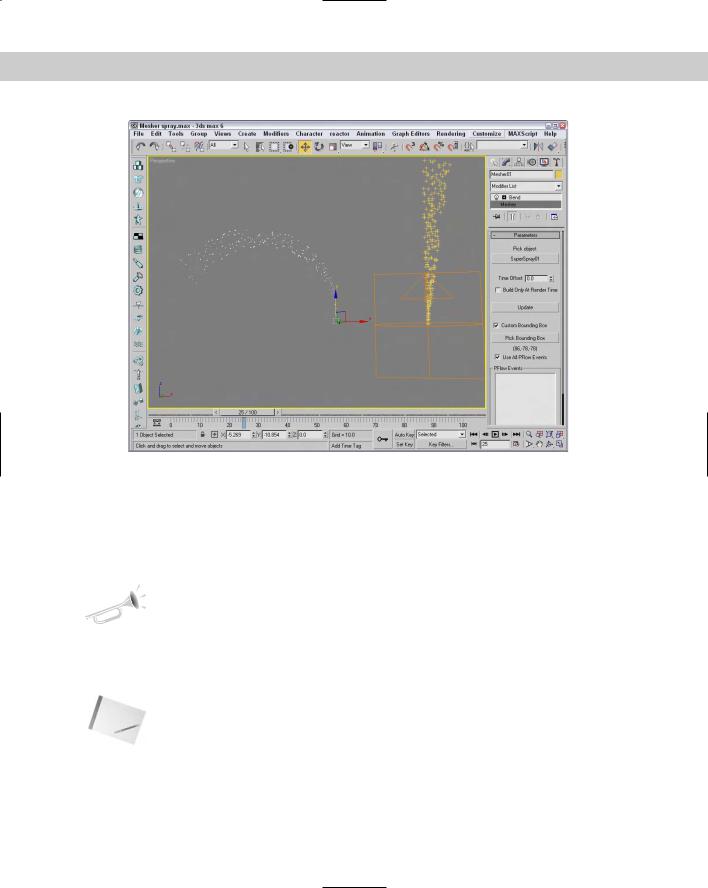
Figure 17-10: You can use the Mesher object to create an instance of a particle system with modifiers applied.
Working with BlobMesh Objects
BlobMesh objects are simple spheres. If you have only one of them, they aren’t interesting at all, but if you get them together, they run into each other much like the metal mercury. This makes them an ideal choice for modeling flowing liquids and soft organic shapes.
New |
The BlobMesh object is new to 3ds max 6. |
Feature |
|
BlobMesh objects are used as sets of objects rather than as individual objects. If you click the BlobMesh button in the Compound Objects subcategory and then create a BlobMesh in the viewports, it appears as a sphere with the radius set using the Size parameter. The real benefit comes from clicking the Pick or Add buttons below the Blob Objects list and selecting an object in the scene.
Note The Pick, Add, and Remove buttons become enabled only in the Modify panel.
The object that is picked is added to the Blob Objects list, and each vertex of the object gets a BlobMesh added to it. If the BlobMesh objects are large enough to overlap, then the entire object is covered with these objects and they run together to form a flowing mass of particles.

Chapter 17 Building Compound Objects 487
Setting BlobMesh Parameters
The Size value sets the radius of the BlobMesh object. Larger sizes result in more overlapping of surrounding objects. For particle systems, the Size is discounted and the size of the particles determines the size of the BlobMesh objects. The Tension value sets how loose or tight the surface of the BlobMesh object is. Small tension values result in looser objects that more readily flow together.
The Evaluation Coarseness value sets how dense the BlobMesh objects will be. By enabling the Relative Coarseness option, the density of the objects changes as the size of the objects changes. The Coarseness values can be different for the viewport and the Render engine.
When a BlobMesh object is selected and applied to the picked object, each vertex has an object attached to it, but if you apply a selection modifier, such as the Mesh Select modifier, to the picked object, then only the selected subobjects get a MeshBlob object. You can also use the Soft Selection option to select those subobjects adjacent to the selected subobjects. The Minimum Size value is the smallest sized BlobMesh object that is used when Soft Selection is enabled.
The Large Data Optimization option is a quicker, more efficient way of rendering a huge set of BlobMesh objects. The benefit from this method comes when more than 2,000 BlobMesh objects need to be rendered. If the viewport updates are slow due to the number of BlobMesh objects, you can select to turn them Off in Viewport.
Cross-
Reference
When BlobMesh objects are applied to a particle system, they can be used as part of a Particle Flow workflow. The Particle Flow Parameters rollout includes a list of events to apply to the BlobMesh objects. Particle Flow is covered in detail in Chapter 18, “Creating Particles and Particle Flow.”
Tutorial: Creating a volcano with BlobMesh objects
When you think of coarse, blobby-like flows of liquid, you might recall that icky science experiment that you did in elementary school where you combined baking soda with vinegar in the center of a red clay structure, trying to make it look like a volcano.
To create a simple volcano using BlobMesh objects, follow these steps:
1.Select the Create Standard Primitives Cone menu command, and drag and click in the Top viewport to create a cone that is flat at the top. Name the object Volcano, and set its color to brown, its Radius 1 value to 135, its Radius 2 to 30, its Height to 170, and its Height Segments to 15.
2.If we applied a BlobMesh to this cone as it is now, all the lava flows would line up perfectly, which isn’t very realistic, so we need to add some noise to the volcano shape. Select the Modifiers Parametric Deformers Noise menu command. For the Noise modifier, enable the Fractal option and set the Strength values to 40, 60, and 70 for the X, Y, and Z axes.
3.Select Create Compound BlobMesh, and click in the Top viewport to create a BlobMesh object. Name the object Lava, and set its color to red and its Size to 23.
4.Open the Modify panel, click the Pick button below the empty Blob Objects list, and select the volcano cone object.
This places a BlobMesh object at each vertex to simulate the lava flowing down the volcano.

488 Part III Modeling
Figure 17-11 shows the resulting volcano scene. For more practice, you can try using a particle system to animate the flowing lava.
Figure 17-11: A volcano object, complete with lava, compliments of the BlobMesh object
Creating a Scatter Object
A Scatter object spreads multiple copies of the object about the scene or within a defined area. The object that is scattered is called the Source object, and the area where the scatter objects can be placed is defined by a Distribution object.
Cross- Particle systems, which are discussed in Chapter 18, “Creating Particles and Particle Flow,” Reference can also create many duplicate objects, but you have more control over the placement of
objects with a Scatter object.
To create a Scatter object, select the Create Compound Scatter menu command. The selected object becomes the Source object. A rollout then opens, in which you can select the Distribution object or use defined transforms.
Under the Scatter Objects rollout, the Objects section lists the Source and Distribution objects. Name fields are also available for changing the name of either object. The Extract Operand button is available only in the Modify panel; it lets you select an operand from the list and make a copy or instance of it.
Chapter 17 Building Compound Objects 489
Working with Source objects
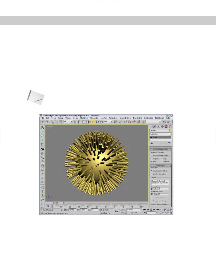
The Source object is the object that is to be duplicated. Figure 17-12 shows a Cylinder primitive scattered over a spherical Distribution object with 500 duplicates. The Perpendicular and Distribute Using Even options are set.
In the Scatter Objects rollout are several parameters for controlling the Source object. In the Source Object Parameters rollout, the Duplicates value specifies how many objects to scatter. You can also specify a Base Scale and the Vertex Chaos values. The Base Scale is the value that the object is scaled to before being scattered. All new objects are scaled equally to this value. The Vertex Chaos button randomly distributes the object vertices.
The Animation Offset defines the number of frames between a new duplicate and the previous one.
Note If you look closely at a Scatter object, you’ll notice that both the Source and Distribution objects have the same object color. To color them differently, use the Multi/Sub-Object Material.
Figure 17-12: A Scatter object made of a Cylinder spread over an area defined by a sphere
490 Part III Modeling
Working with Distribution objects
To select a Distribution object, click the Pick Distribution Object button and select an object in the viewport (make sure that the Use Distribution Object option is selected in the Scatter Objects rollout). You can specify the Distribution object as a Copy, Instance, Reference,
or Move.
Under the Distribution Object Parameters rollout are several options for controlling the Distribution object. The Perpendicular option causes the Source objects to be aligned perpendicular to the Distribution object. If the Perpendicular option is disabled, the orientation remains the same as that of the default Source object. Figure 17-13 shows the same Scatter object as in the preceding figure, but with several different options.
Figure 17-13: A Scatter object with different options: Base Scale at 20%, Vertex Chaos at 2.0, Perpendicular option disabled, and Duplicates at 100
The Use Selected Faces Only option enables you to select the faces over which the duplicates are positioned. The Selected Faces are those passed up the Stack by the Mesh Select modifier.
Other Distribution object parameter options include Area, Even, Skip N, Random Faces, Along Edges, All Vertices, All Edge Midpoints, All Face Centers, and Volume. The Area option evenly distributes the objects over the surface area, and the Even option places duplicates over every other face. The Skip N option lets you specify how many faces to skip before placing an object. The Random Faces and Along Edges options randomly distribute the duplicates around the Distribution object. The All Vertices, All Edge Midpoints, and All Face Centers options ignore the Duplicates value (that specifies the number of duplicates) and place a duplicate
at every vertex, edge midpoint, and face. Figure 17-14 shows several of these options.
Figure 17-14: A Scatter object with different distribution options: Area,
Skip N where N=7, Random Faces, All Vertices, and All Face Centers
All the options described thus far place the duplicates on the surface of the object, but the Volume option scatters the duplicates inside the Distribution object’s volume.
Setting Transforms
The Transforms rollout is used to specify the individual transformation limits of the duplicate objects. For example, if the Z-axis value is set to 90, then each new duplicate is randomly rotated about its local Z axis at a distance somewhere between –90 and 90.

Chapter 17 Building Compound Objects 491
You can use these transformations with a Distribution object or by themselves if the Use Transforms Only option is selected under the Scatter Objects rollout. The Use Maximum Range option causes all three axes to adopt the same value. The Lock Aspect Ratio option maintains the relative dimensions of the Source object to ensure uniform scaling.
Speeding updates with a proxy
Working with a large number of duplicates can slow the viewport updates to a crawl. To speed these updates, select the Proxy option in the Display rollout. This option replaces each duplicate with a wedge-shaped object. For example, if you used the Scatter object to place people on a sidewalk, you can use the Proxy option to display simple cylinders in the viewports instead of the details of the person mesh.
Another way to speed the viewport updates is to use the Display spinner. Using this spinner, you can select a percentage of the total number of duplicates to display in the viewport. The rendered image still uses the actual number specified.
The Hide Distribution Object option lets you make the Distribution object visible or invisible. The Seed value is used to determine the randomness of the objects.
Loading and saving presets
With all the various parameters, the Load/Save Presets rollout enables you to Save, Load, or Delete various presets. You can use saved presets with another Source object.
Tutorial: Filling a box with spiders
When I was a kid, my brothers and I always had a terrarium full of snakes, lizards, or spiders. Mom was okay with this as long as we remembered the one key rule: Keep the lid on. Well, kids will be kids, and at times we forgot. Then it was spiders everywhere (and you thought this effect was only good for horror flicks — it also works well on little sisters).
To scatter spiders across the surface of a box, follow these steps:
1.Open the Scatter box of spiders.max file from the Chap 17 directory on the CD-ROM. This file includes a simple box mesh and a spider mesh.
2.With the spider object selected, select the Create Compound Scatter menu command.
3.In the Pick Distribution Object rollout, click the Pick Distribution Object button and click the box object. Select the Move option.
4.In the Source Object Parameters section of the Scatter Objects rollout, enter a value of 60 in the Duplicates field.
5.Select the Perpendicular and Even options in the Distribution Object Parameters section, and watch the spiders spread across the surface of the box.
Figure 17-15 shows the spiders creeping about. Notice that the box and spiders are all part of the same object and have the same object color.

492 Part III Modeling
Figure 17-15: Spiders spread over the box surface using the Scatter object
Tutorial: Creating jungle vines
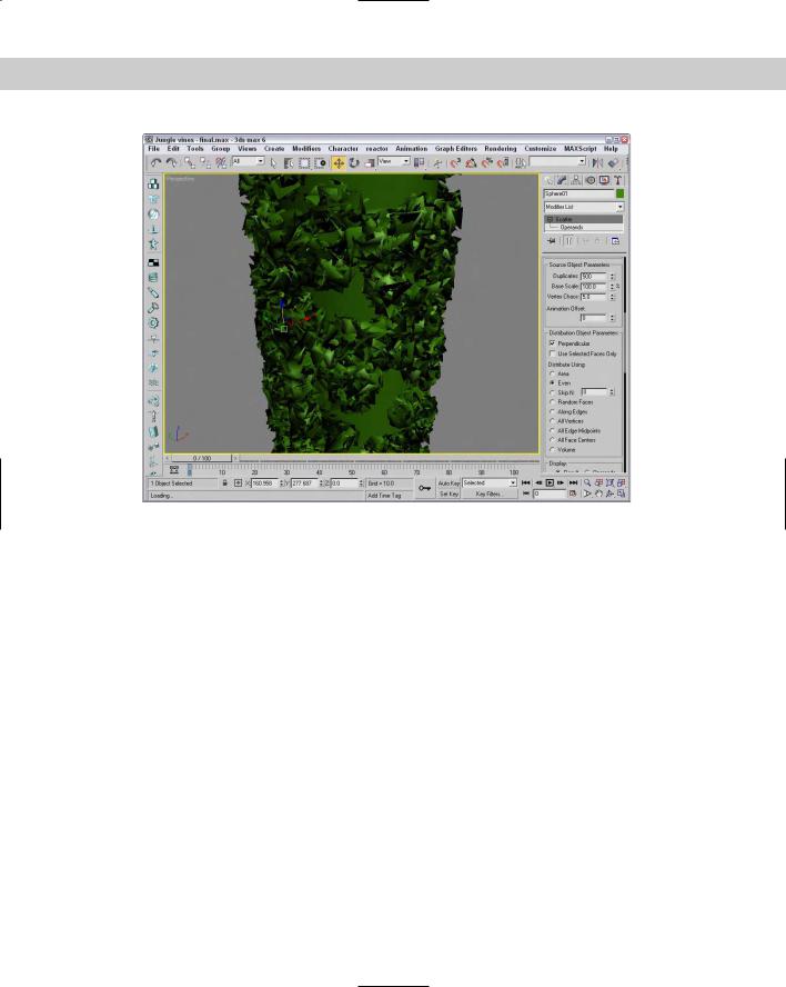
You can use the Vertex Chaos setting to randomly order the vertices of an object. You can use this randomness to simulate random natural patterns like foliage growing on a pillar. Using the Vertex Chaos value, you can simulate the effect of jungle vines growing thick upon the surface of an object.
To cover an object with jungle vines, follow these steps:
1.Open the Jungle vine.max file from the Chap 17 directory on the CD-ROM.
This file includes a simple cylinder and a small sphere with its object color set to dark green.
2.With the sphere object selected, select the Create Compound Scatter menu command.
3.Click the Pick Distribution Object button, and select the cylinder with the Move option selected.
4.In the Scatter Objects rollout, set the number of Duplicates to 500 and the Vertex Chaos value to 5 (lower the number of Duplicates if necessary).
Figure 17-16 shows the resulting overgrowth.
Chapter 17 Building Compound Objects 493
Figure 17-16: You can use the Scatter object and the Vertex Chaos option to create the look of jungle vines growing on a pillar.
Tutorial: Covering the island with trees
You can combine several different types of compound objects to create interesting effects. In this tutorial, we add trees to the Terrain object island created earlier in this chapter using the Scatter object.
To add trees to the island with the Scatter object, follow these steps:
1.Open the Island terrain with trees.max file from the Chap 17 directory on the CD-ROM.
This file is the same island terrain example that you completed earlier in this chapter, but it also has a simple tree added to it.
2.With the tree object selected, select the Create Compound Scatter menu command.
3.Click the Pick Distribution Object button, and select the island terrain. Set the number of Duplicates to 100, and disable the Perpendicular option.
All the trees now stand upright.
4.Select the Random Faces option.
The trees become denser around the hills where there are more faces.
Figure 17-17 shows the island with the trees.