

- •Preface
- •About This Book
- •Acknowledgments
- •Contents at a Glance
- •Contents
- •Relaxing at the Beach
- •Dressing the Scene
- •Animating Motion
- •Rendering the Final Animation
- •Summary
- •The Interface Elements
- •Using the Menus
- •Using the Toolbars
- •Using the Viewports
- •Using the Command Panel
- •Using the Lower Interface Bar Controls
- •Interacting with the Interface
- •Getting Help
- •Summary
- •Understanding 3D Space
- •Using the Viewport Navigation Controls
- •Configuring the Viewports
- •Working with Viewport Backgrounds
- •Summary
- •Working with Max Scene Files
- •Setting File Preferences
- •Importing and Exporting
- •Referencing External Objects
- •Using the File Utilities
- •Accessing File Information
- •Summary
- •Customizing Modify and Utility Panel Buttons
- •Working with Custom Interfaces
- •Configuring Paths
- •Selecting System Units
- •Setting Preferences
- •Summary
- •Creating Primitive Objects
- •Exploring the Primitive Object Types
- •Summary
- •Selecting Objects
- •Setting Object Properties
- •Hiding and Freezing Objects
- •Using Layers
- •Summary
- •Cloning Objects
- •Understanding Cloning Options
- •Mirroring Objects
- •Cloning over Time
- •Spacing Cloned Objects
- •Creating Arrays of Objects
- •Summary
- •Working with Groups
- •Building Assemblies
- •Building Links between Objects
- •Displaying Links and Hierarchies
- •Working with Linked Objects
- •Summary
- •Using the Schematic View Window
- •Working with Hierarchies
- •Setting Schematic View Preferences
- •Using List Views
- •Summary
- •Working with the Transformation Tools
- •Using Pivot Points
- •Using the Align Commands
- •Using Grids
- •Using Snap Options
- •Summary
- •Exploring the Modifier Stack
- •Exploring Modifier Types
- •Summary
- •Exploring the Modeling Types
- •Working with Subobjects
- •Modeling Helpers
- •Summary
- •Drawing in 2D
- •Editing Splines
- •Using Spline Modifiers
- •Summary
- •Creating Editable Mesh and Poly Objects
- •Editing Mesh Objects
- •Editing Poly Objects
- •Using Mesh Editing Modifiers
- •Summary
- •Introducing Patch Grids
- •Editing Patches
- •Using Modifiers on Patch Objects
- •Summary
- •Creating NURBS Curves and Surfaces
- •Editing NURBS
- •Working with NURBS
- •Summary
- •Morphing Objects
- •Creating Conform Objects
- •Creating a ShapeMerge Object
- •Creating a Terrain Object
- •Using the Mesher Object
- •Working with BlobMesh Objects
- •Creating a Scatter Object
- •Creating Connect Objects
- •Modeling with Boolean Objects
- •Creating a Loft Object
- •Summary
- •Understanding the Various Particle Systems
- •Creating a Particle System
- •Using the Spray and Snow Particle Systems
- •Using the Super Spray Particle System
- •Using the Blizzard Particle System
- •Using the PArray Particle System
- •Using the PCloud Particle System
- •Using Particle System Maps
- •Controlling Particles with Particle Flow
- •Summary
- •Understanding Material Properties
- •Working with the Material Editor
- •Using the Material/Map Browser
- •Using the Material/Map Navigator
- •Summary
- •Using the Standard Material
- •Using Shading Types
- •Accessing Other Parameters
- •Using External Tools
- •Summary
- •Using Compound Materials
- •Using Raytrace Materials
- •Using the Matte/Shadow Material
- •Using the DirectX 9 Shader
- •Applying Multiple Materials
- •Material Modifiers
- •Summary
- •Understanding Maps
- •Understanding Material Map Types
- •Using the Maps Rollout
- •Using the Map Path Utility
- •Using Map Instances
- •Summary
- •Mapping Modifiers
- •Using the Unwrap UVW modifier
- •Summary
- •Working with Cameras
- •Setting Camera Parameters
- •Summary
- •Using the Camera Tracker Utility
- •Summary
- •Using Multi-Pass Cameras
- •Creating Multi-Pass Camera Effects
- •Summary
- •Understanding the Basics of Lighting
- •Getting to Know the Light Types
- •Creating and Positioning Light Objects
- •Viewing a Scene from a Light
- •Altering Light Parameters
- •Working with Photometric Lights
- •Using the Sunlight and Daylight Systems
- •Using Volume Lights
- •Summary
- •Selecting Advanced Lighting
- •Using Local Advanced Lighting Settings
- •Tutorial: Excluding objects from light tracing
- •Summary
- •Understanding Radiosity
- •Using Local and Global Advanced Lighting Settings
- •Working with Advanced Lighting Materials
- •Using Lighting Analysis
- •Summary
- •Using the Time Controls
- •Working with Keys
- •Using the Track Bar
- •Viewing and Editing Key Values
- •Using the Motion Panel
- •Using Ghosting
- •Animating Objects
- •Working with Previews
- •Wiring Parameters
- •Animation Modifiers
- •Summary
- •Understanding Controller Types
- •Assigning Controllers
- •Setting Default Controllers
- •Examining the Various Controllers
- •Summary
- •Working with Expressions in Spinners
- •Understanding the Expression Controller Interface
- •Understanding Expression Elements
- •Using Expression Controllers
- •Summary
- •Learning the Track View Interface
- •Working with Keys
- •Editing Time
- •Editing Curves
- •Filtering Tracks
- •Working with Controllers
- •Synchronizing to a Sound Track
- •Summary
- •Understanding Your Character
- •Building Bodies
- •Summary
- •Building a Bones System
- •Using the Bone Tools
- •Using the Skin Modifier
- •Summary
- •Creating Characters
- •Working with Characters
- •Using Character Animation Techniques
- •Summary
- •Forward versus Inverse Kinematics
- •Creating an Inverse Kinematics System
- •Using the Various Inverse Kinematics Methods
- •Summary
- •Creating and Binding Space Warps
- •Understanding Space Warp Types
- •Combining Particle Systems with Space Warps
- •Summary
- •Understanding Dynamics
- •Using Dynamic Objects
- •Defining Dynamic Material Properties
- •Using Dynamic Space Warps
- •Using the Dynamics Utility
- •Using the Flex Modifier
- •Summary
- •Using reactor
- •Using reactor Collections
- •Creating reactor Objects
- •Calculating and Previewing a Simulation
- •Constraining Objects
- •reactor Troubleshooting
- •Summary
- •Understanding the Max Renderers
- •Previewing with ActiveShade
- •Render Parameters
- •Rendering Preferences
- •Creating VUE Files
- •Using the Rendered Frame Window
- •Using the RAM Player
- •Reviewing the Render Types
- •Using Command-Line Rendering
- •Creating Panoramic Images
- •Getting Printer Help
- •Creating an Environment
- •Summary
- •Creating Atmospheric Effects
- •Using the Fire Effect
- •Using the Fog Effect
- •Summary
- •Using Render Elements
- •Adding Render Effects
- •Creating Lens Effects
- •Using Other Render Effects
- •Summary
- •Using Raytrace Materials
- •Using a Raytrace Map
- •Enabling mental ray
- •Summary
- •Understanding Network Rendering
- •Network Requirements
- •Setting up a Network Rendering System
- •Starting the Network Rendering System
- •Configuring the Network Manager and Servers
- •Logging Errors
- •Using the Monitor
- •Setting up Batch Rendering
- •Summary
- •Compositing with Photoshop
- •Video Editing with Premiere
- •Video Compositing with After Effects
- •Introducing Combustion
- •Using Other Compositing Solutions
- •Summary
- •Completing Post-Production with the Video Post Interface
- •Working with Sequences
- •Adding and Editing Events
- •Working with Ranges
- •Working with Lens Effects Filters
- •Summary
- •What Is MAXScript?
- •MAXScript Tools
- •Setting MAXScript Preferences
- •Types of Scripts
- •Writing Your Own MAXScripts
- •Learning the Visual MAXScript Editor Interface
- •Laying Out a Rollout
- •Summary
- •Working with Plug-Ins
- •Locating Plug-Ins
- •Summary
- •Low-Res Modeling
- •Using Channels
- •Using Vertex Colors
- •Rendering to a Texture
- •Summary
- •Max and Architecture
- •Using AEC Objects
- •Using Architectural materials
- •Summary
- •Tutorial: Creating Icy Geometry with BlobMesh
- •Tutorial: Using Caustic Photons to Create a Disco Ball
- •Summary
- •mental ray Rendering System
- •Particle Flow
- •reactor 2.0
- •Schematic View
- •BlobMesh
- •Spline and Patch Features
- •Import and Export
- •Shell Modifier
- •Vertex Paint and Channel Info
- •Architectural Primitives and Materials
- •Minor Improvements
- •Choosing an Operating System
- •Hardware Requirements
- •Installing 3ds max 6
- •Authorizing the Software
- •Setting the Display Driver
- •Updating Max
- •Moving Max to Another Computer
- •Using Keyboard Shortcuts
- •Using the Hotkey Map
- •Main Interface Shortcuts
- •Dialog Box Shortcuts
- •Miscellaneous Shortcuts
- •System Requirements
- •Using the CDs with Windows
- •What’s on the CDs
- •Troubleshooting
- •Index
Chapter 45 Network Rendering 1067
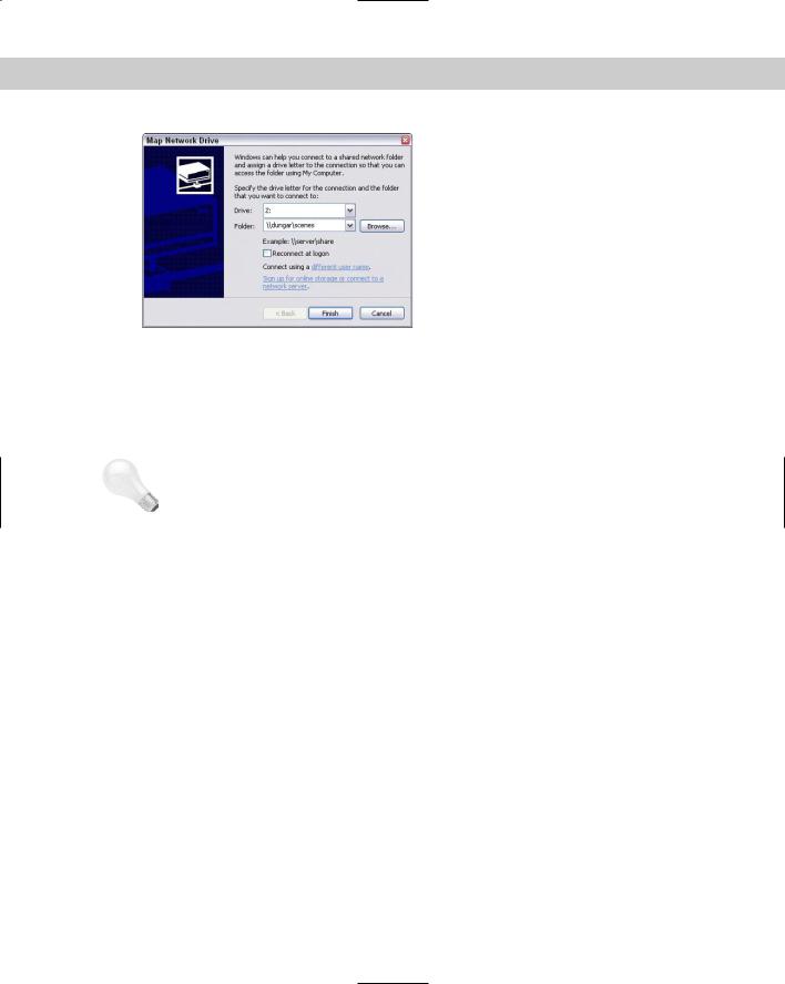
Figure 45-5: Mapping the Z drive to point to \\dungar\scenes\.
To set up your shared directories, follow these steps:
1.First, decide which drives to use and then share them. On my network, Dungar has plenty of disk space, so I used the maps, images, and scenes directories that were already there from when I installed Max.
Tip |
Use the maps, images, and scenes directories for all the scenes that you render via a net- |
|
work. In each directory, you can create other directories to organize files for your different |
|
scenes, but putting all needed files in the same place facilitates maintenance. |
2.On each computer in your rendering farm, map a drive to your shared maps, images, and scenes directories as described in the previous section. If possible, choose the same drive letters on all machines. I used the letter Z for the maps directory on each computer.
Congratulations! You’ve made it through the installation and setup of your network rendering system. And no matter how long it took you, it was time well spent. The ability to render via a network will easily save you more time than you invested in setting up your network.
Starting the Network Rendering System
You can finally put all your hard work into action. We’re ready to start up your network rendering system.
Tutorial: Initializing the network rendering system
The very first time you start your rendering farm, you need to help Max do a little initialization.
To initialize the network rendering system, follow these steps:
1.Start the network manager on one machine in your rendering farm. This program, Manager.exe, is in the backburner2 directory. You can start the manager by selecting it

1068 Part X Rendering
and pressing Enter in Windows Explorer. After it starts up, you first see the backburner Manager General Properties dialog box. This dialog box appears only the first time you run the Manager.exe program or if you choose Edit General Settings. I cover its settings later in the chapter. After setting these properties, click the OK button, and the Manager window, shown in Figure 45-6, runs.
Figure 45-6: Starting the network manager
2.Now start a network server on each computer that you plan to use for rendering. To do this, find and start the Server.exe program just like you did with Manager.exe. When you start this program for the first time, the backburner Server General Properties dialog box appears. This dialog box is covered later in the chapter. Click OK, and the Network Server window appears, as shown in Figure 45-7.
Figure 45-7: Starting a network server. Notice that the server is already looking for the manager.
When the server finds the manager, it displays a message that the registration is accepted. The Network Manager window also shows a similar message.
If the server had trouble connecting to the manager, you need to follow these two additional steps:
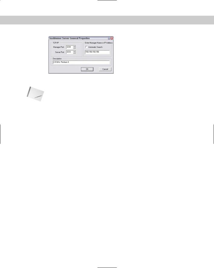
1.If automatic detection of the manager fails, the server keeps trying until it times out. If it times out, or if you just get tired of waiting, choose Edit General Settings to open the backburner Server General Properties dialog box, shown in Figure 45-8. In this dialog box, uncheck the Automatic Search box and type in the name or IP address of the computer that is running the network manager. In this case, the server tried but couldn’t quite find the manager, so it had to be told that the manager was running on the computer whose IP address is 150.150.150.150.
2.Click OK to close the backburner Server General Properties dialog box, and then click Close to shut down the server (doing so forces the server to save the changes you’ve made). Restart the server the same way you did before, and now the server and manager are able to find each other.
Chapter 45 Network Rendering 1069
Figure 45-8: Manually choosing the manager’s IP address
Note The network manager does not need to have a computer all to itself, so you can also run a network server on the same computer and use it to participate in the rendering.
Tutorial: Completing your first network rendering job
Your rendering farm is up and running and just dying to render something, so let’s put those machines to work.
To start a network rendering job, follow these steps:
1.Start Max, and create a simple animation scene.
This should be as simple as possible because all we’re doing here is verifying that the rendering farm is functional.
2.In Max, choose Rendering Render (F10) to bring up the Render Scene dialog box. In the Time Output section of this dialog box, be sure that Range is selected so that you really do render multiple frames instead of the default single frame.
3.In the Render Output section of the Render Scene dialog box, click Files to open the Render Output File dialog box. In the Save In section, choose the output drive and directory that you created in the “Configuring shared directories” section.
4.In the File name section of the Render Output File dialog box, type in the name of the first frame. Max automatically numbers each frame for you. Choose a bitmap format from the Save as type list (remember, an animation format will not work).
5.Click Save to close the Render Output File dialog box. (Some file formats might ask you for additional information for your files; if so, just click OK to accept the default options.) Back in the Render Scene dialog box, Max displays the full path to the output directory.
6.In the Render Output section of the Render Scene dialog box, check the Net Render box, as shown in Figure 45-9. Change any other settings you want, such as selecting a viewport, and then click Render.
A Network Job Assignment dialog box opens, like the one shown in Figure 45-10.
1070 Part X Rendering
Figure 45-9: The Net Render option must be enabled to start a network rendering job.
Figure 45-10: Using the Network Job Assignment dialog box to locate the manager to handle the rendering job

Chapter 45 Network Rendering 1071
7.In the Enter Subnet section of the Network Job Assignment dialog box, click Connect if the Automatic Search box is checked. If it isn’t checked, or if your servers had trouble finding the manager in the “Initializing the network rendering system” tutorial earlier in this chapter, type in the IP address of the machine that’s running the manager and then click Connect.
8.Max then searches for any available rendering servers, connects with it, and adds its name to the list of available servers. Click the server name once, and click Submit.
Tip |
If you try to submit the same job again (after either a failed or a successful attempt at ren- |
|
dering), Max complains because that job already exists in the job queue. You can remove the |
|
job using the Monitor, or you can click the + button on the Network Job Assignment dialog |
|
box, and Max adds a number to the job name to make it unique. |
After you’ve submitted your job, notices appear on the manager and the servers (like the ones shown in Figures 45-11 and 45-12) that the job has been received. Soon Max starts up on each server, and you see a Rendering dialog box showing the progress of the rendering task. As you can see, this displays useful information such as what frame is being rendered and how long the job is taking. When the entire animation has been rendered, you can go to your output directory to get the bitmap files that Max generated. The render servers and the render manager keep running, ready for the next job request to come in.
Figure 45-11: The network manager detects the new job.
Figure 45-12: One of the network servers receives the command to start a new job.
Job assignment options
The Network Job Assignment dialog box, shown previously in Figure 45-10, has an important section that we didn’t use for our first simple render job called Options.