

- •Preface
- •About This Book
- •Acknowledgments
- •Contents at a Glance
- •Contents
- •Relaxing at the Beach
- •Dressing the Scene
- •Animating Motion
- •Rendering the Final Animation
- •Summary
- •The Interface Elements
- •Using the Menus
- •Using the Toolbars
- •Using the Viewports
- •Using the Command Panel
- •Using the Lower Interface Bar Controls
- •Interacting with the Interface
- •Getting Help
- •Summary
- •Understanding 3D Space
- •Using the Viewport Navigation Controls
- •Configuring the Viewports
- •Working with Viewport Backgrounds
- •Summary
- •Working with Max Scene Files
- •Setting File Preferences
- •Importing and Exporting
- •Referencing External Objects
- •Using the File Utilities
- •Accessing File Information
- •Summary
- •Customizing Modify and Utility Panel Buttons
- •Working with Custom Interfaces
- •Configuring Paths
- •Selecting System Units
- •Setting Preferences
- •Summary
- •Creating Primitive Objects
- •Exploring the Primitive Object Types
- •Summary
- •Selecting Objects
- •Setting Object Properties
- •Hiding and Freezing Objects
- •Using Layers
- •Summary
- •Cloning Objects
- •Understanding Cloning Options
- •Mirroring Objects
- •Cloning over Time
- •Spacing Cloned Objects
- •Creating Arrays of Objects
- •Summary
- •Working with Groups
- •Building Assemblies
- •Building Links between Objects
- •Displaying Links and Hierarchies
- •Working with Linked Objects
- •Summary
- •Using the Schematic View Window
- •Working with Hierarchies
- •Setting Schematic View Preferences
- •Using List Views
- •Summary
- •Working with the Transformation Tools
- •Using Pivot Points
- •Using the Align Commands
- •Using Grids
- •Using Snap Options
- •Summary
- •Exploring the Modifier Stack
- •Exploring Modifier Types
- •Summary
- •Exploring the Modeling Types
- •Working with Subobjects
- •Modeling Helpers
- •Summary
- •Drawing in 2D
- •Editing Splines
- •Using Spline Modifiers
- •Summary
- •Creating Editable Mesh and Poly Objects
- •Editing Mesh Objects
- •Editing Poly Objects
- •Using Mesh Editing Modifiers
- •Summary
- •Introducing Patch Grids
- •Editing Patches
- •Using Modifiers on Patch Objects
- •Summary
- •Creating NURBS Curves and Surfaces
- •Editing NURBS
- •Working with NURBS
- •Summary
- •Morphing Objects
- •Creating Conform Objects
- •Creating a ShapeMerge Object
- •Creating a Terrain Object
- •Using the Mesher Object
- •Working with BlobMesh Objects
- •Creating a Scatter Object
- •Creating Connect Objects
- •Modeling with Boolean Objects
- •Creating a Loft Object
- •Summary
- •Understanding the Various Particle Systems
- •Creating a Particle System
- •Using the Spray and Snow Particle Systems
- •Using the Super Spray Particle System
- •Using the Blizzard Particle System
- •Using the PArray Particle System
- •Using the PCloud Particle System
- •Using Particle System Maps
- •Controlling Particles with Particle Flow
- •Summary
- •Understanding Material Properties
- •Working with the Material Editor
- •Using the Material/Map Browser
- •Using the Material/Map Navigator
- •Summary
- •Using the Standard Material
- •Using Shading Types
- •Accessing Other Parameters
- •Using External Tools
- •Summary
- •Using Compound Materials
- •Using Raytrace Materials
- •Using the Matte/Shadow Material
- •Using the DirectX 9 Shader
- •Applying Multiple Materials
- •Material Modifiers
- •Summary
- •Understanding Maps
- •Understanding Material Map Types
- •Using the Maps Rollout
- •Using the Map Path Utility
- •Using Map Instances
- •Summary
- •Mapping Modifiers
- •Using the Unwrap UVW modifier
- •Summary
- •Working with Cameras
- •Setting Camera Parameters
- •Summary
- •Using the Camera Tracker Utility
- •Summary
- •Using Multi-Pass Cameras
- •Creating Multi-Pass Camera Effects
- •Summary
- •Understanding the Basics of Lighting
- •Getting to Know the Light Types
- •Creating and Positioning Light Objects
- •Viewing a Scene from a Light
- •Altering Light Parameters
- •Working with Photometric Lights
- •Using the Sunlight and Daylight Systems
- •Using Volume Lights
- •Summary
- •Selecting Advanced Lighting
- •Using Local Advanced Lighting Settings
- •Tutorial: Excluding objects from light tracing
- •Summary
- •Understanding Radiosity
- •Using Local and Global Advanced Lighting Settings
- •Working with Advanced Lighting Materials
- •Using Lighting Analysis
- •Summary
- •Using the Time Controls
- •Working with Keys
- •Using the Track Bar
- •Viewing and Editing Key Values
- •Using the Motion Panel
- •Using Ghosting
- •Animating Objects
- •Working with Previews
- •Wiring Parameters
- •Animation Modifiers
- •Summary
- •Understanding Controller Types
- •Assigning Controllers
- •Setting Default Controllers
- •Examining the Various Controllers
- •Summary
- •Working with Expressions in Spinners
- •Understanding the Expression Controller Interface
- •Understanding Expression Elements
- •Using Expression Controllers
- •Summary
- •Learning the Track View Interface
- •Working with Keys
- •Editing Time
- •Editing Curves
- •Filtering Tracks
- •Working with Controllers
- •Synchronizing to a Sound Track
- •Summary
- •Understanding Your Character
- •Building Bodies
- •Summary
- •Building a Bones System
- •Using the Bone Tools
- •Using the Skin Modifier
- •Summary
- •Creating Characters
- •Working with Characters
- •Using Character Animation Techniques
- •Summary
- •Forward versus Inverse Kinematics
- •Creating an Inverse Kinematics System
- •Using the Various Inverse Kinematics Methods
- •Summary
- •Creating and Binding Space Warps
- •Understanding Space Warp Types
- •Combining Particle Systems with Space Warps
- •Summary
- •Understanding Dynamics
- •Using Dynamic Objects
- •Defining Dynamic Material Properties
- •Using Dynamic Space Warps
- •Using the Dynamics Utility
- •Using the Flex Modifier
- •Summary
- •Using reactor
- •Using reactor Collections
- •Creating reactor Objects
- •Calculating and Previewing a Simulation
- •Constraining Objects
- •reactor Troubleshooting
- •Summary
- •Understanding the Max Renderers
- •Previewing with ActiveShade
- •Render Parameters
- •Rendering Preferences
- •Creating VUE Files
- •Using the Rendered Frame Window
- •Using the RAM Player
- •Reviewing the Render Types
- •Using Command-Line Rendering
- •Creating Panoramic Images
- •Getting Printer Help
- •Creating an Environment
- •Summary
- •Creating Atmospheric Effects
- •Using the Fire Effect
- •Using the Fog Effect
- •Summary
- •Using Render Elements
- •Adding Render Effects
- •Creating Lens Effects
- •Using Other Render Effects
- •Summary
- •Using Raytrace Materials
- •Using a Raytrace Map
- •Enabling mental ray
- •Summary
- •Understanding Network Rendering
- •Network Requirements
- •Setting up a Network Rendering System
- •Starting the Network Rendering System
- •Configuring the Network Manager and Servers
- •Logging Errors
- •Using the Monitor
- •Setting up Batch Rendering
- •Summary
- •Compositing with Photoshop
- •Video Editing with Premiere
- •Video Compositing with After Effects
- •Introducing Combustion
- •Using Other Compositing Solutions
- •Summary
- •Completing Post-Production with the Video Post Interface
- •Working with Sequences
- •Adding and Editing Events
- •Working with Ranges
- •Working with Lens Effects Filters
- •Summary
- •What Is MAXScript?
- •MAXScript Tools
- •Setting MAXScript Preferences
- •Types of Scripts
- •Writing Your Own MAXScripts
- •Learning the Visual MAXScript Editor Interface
- •Laying Out a Rollout
- •Summary
- •Working with Plug-Ins
- •Locating Plug-Ins
- •Summary
- •Low-Res Modeling
- •Using Channels
- •Using Vertex Colors
- •Rendering to a Texture
- •Summary
- •Max and Architecture
- •Using AEC Objects
- •Using Architectural materials
- •Summary
- •Tutorial: Creating Icy Geometry with BlobMesh
- •Tutorial: Using Caustic Photons to Create a Disco Ball
- •Summary
- •mental ray Rendering System
- •Particle Flow
- •reactor 2.0
- •Schematic View
- •BlobMesh
- •Spline and Patch Features
- •Import and Export
- •Shell Modifier
- •Vertex Paint and Channel Info
- •Architectural Primitives and Materials
- •Minor Improvements
- •Choosing an Operating System
- •Hardware Requirements
- •Installing 3ds max 6
- •Authorizing the Software
- •Setting the Display Driver
- •Updating Max
- •Moving Max to Another Computer
- •Using Keyboard Shortcuts
- •Using the Hotkey Map
- •Main Interface Shortcuts
- •Dialog Box Shortcuts
- •Miscellaneous Shortcuts
- •System Requirements
- •Using the CDs with Windows
- •What’s on the CDs
- •Troubleshooting
- •Index

Chapter 23 Controlling Mapping Coordinates |
643 |
Using the Unwrap UVW modifier
The Unwrap UVW modifier lets you control how a map is applied to a subobject selection. It can also be used to unwrap the existing mapping coordinates of an object. You can then edit these coordinates as needed. You can also use the Unwrap UVW modifier to apply multiple planar maps to an object. You accomplish this task by creating planar maps for various sides of an object and then editing the mapping coordinates in the Edit UVWs interface.
The Unwrap UVW modifier lets you control precisely how a map is applied to an object. The Unwrap UVW modifier has a single subobject mode named Select Face. In this subobject mode, you can select face subobjects, and the same face selection is displayed in the Edit UVWs interface and vice versa. In the Modify panel, you’ll find two rollouts: Selection Parameters and Parameters. The Selection Parameters rollout includes a button with a plus sign and one with a minus sign. These buttons grow or shrink the current selected subobject selection. You can also select to Ignore Backfacing, Select by Element (instead of faces), set the Planar Angle, or select by Material ID or Smoothing Group.
The Edit UVWs interface
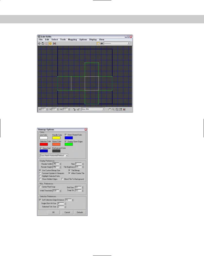
The Parameters rollout includes a button named Edit. This button opens the Edit UVWs interface, shown in Figure 23-5 for a simple cube. You can also load and save the edited mapping coordinates using the Save and Load buttons in the Parameters rollout, and the Reset UVWs button resets all the mapped coordinates. Saved mapping coordinate files have the .UVW extension.
Figure 23-5: The Edit UVWs interface lets you control how different planar maps line up with the model.
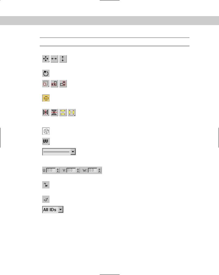
Table 23-1 shows and describes the buttons in the Edit UVWs dialog box.
644 Part IV Materials and Maps
Table 23-1: Edit UVW Interface Buttons
Buttons |
Name |
Description |
|
|
|
|
Move, |
Moves the selected vertices when |
|
Move Horizontal, |
dragged. |
|
Move Vertical |
|
|
Rotate |
Rotates the selected vertices when |
|
|
dragged. |
|
Scale, Scale |
Scales the selected vertices when |
|
Horizontal, |
dragged. |
|
Scale Vertical |
|
|
Freeform Mode |
Displays a gizmo that you can use |
|
|
to transform the subobject |
|
|
selection. |
|
Mirror Horizontal, |
Mirrors or flips the selected |
|
Mirror Vertical, |
vertices about the center of |
|
Flip Horizontal, |
the selection. |
|
Flip Vertical |
|
|
Show Map |
Toggles the display of the map in |
|
|
the dialog box. |
|
Coordinates |
Displays the vertices for the UV, |
|
|
UW, and WU axes. |
|
Pick Texture |
Displays a drop-down list of all the |
|
drop-down list |
maps applied to this object. You |
|
|
can display new maps by using the |
|
|
Pick Texture option. |
|
U, V, W values |
Displays the coordinates of the |
|
|
selected vertex. You can use these |
|
|
values to move a vertex. |
|
Lock Selected |
Locks the selected vertices and |
|
Vertices |
prevents additional vertices from |
|
|
being selected. |
|
Filter Selected |
Displays vertices for only the |
|
Faces |
selected faces. |
|
All IDs |
Filters selected material IDs. |
|
drop-down list |
|
|
|
|
The buttons in the lower-right corner of the Edit UVWs dialog box work just like the Viewport Navigation buttons described in earlier chapters.
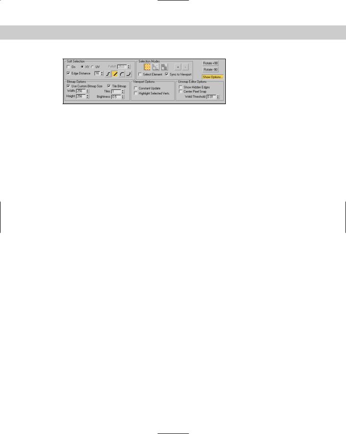
Many of the commands found in the menus can also be found in the pop-up Options interface, shown in Figure 23-6. You can enable Soft Selection using this dialog box. In the Bitmap Options section, you can specify the resolution of the bitmap. You can expand this interface by clicking on the Show Options button.
Chapter 23 Controlling Mapping Coordinates |
645 |
Figure 23-6: The Options pop-up interface includes many of the same features as the menus.
The File menu can also be used to load (Alt+Shift+Ctrl+L), save, and reset UV coordinates. The Edit menu lets you specify the mode to use to transform subobject selections. These modes include Move (Q), Rotate (Ctrl+R), Scale, and Freeform, which lets you use the gizmo to transform subobjects. The Edit menu also includes Copy and Paste and a Paste Weld command. The Copy and Paste commands let you copy a mapping and paste it to another set of faces. The Paste Weld command welds vertices as it pastes the mapping.
The gizmo is simply a rectangle gizmo that surrounds the current selection. Move the selection by clicking in the gizmo and dragging; Shift+dragging constrains the selection to move horizontally or vertically. The plus sign in the center marks the rotation and scale center point. Scale the selection by dragging on one of its handles. Ctrl+dragging on a handle maintains the aspect ratio of the selection. Click and drag the middle handles to rotate the selection. Ctrl+dragging snaps to 5-degree positions, and Alt+dragging snaps to 1-degree positions.
Within the Edit UVWs interface, you can select vertices, edges, or faces. The Select Get Selection From Viewport (Alt+Shift+Ctrl+P) menu command lets you select and transfer the selection from the viewports, or you can convert selections between vertices, edges, and faces. Subobjects that are selected in one planar map are also highlighted in the other planar maps. This makes it easy to stitch elements together.
The Tools menu includes commands for flipping, mirroring, welding, breaking, and detaching subobjects. The Tools Stitch Selected menu command lets you stitch mapped segments together into a single cluster, and the Pack UVs menu command lets you combine UVs into a smaller space. Packed UVs are easy to move and work with because they use a smaller resolution bitmap. Within the Pack dialog box, the Spacing value sets the amount of space between each segment, and the Normalize Clusters option fits all clusters into the given space. The Rotate Clusters option allows segments to be rotated to fit better, and the Fill Holes option places smaller segments within open larger segments.
The Tools Sketch Vertices command lets you select vertices by dragging over them. The vertices can then be aligned to a shape including Line, Circle, Box, or Freeform. You can also set the cursor size used to select vertices.
The Mapping menu includes three auto-mapping options: Flatten, Normal, and Unfold Mapping. The Flatten Mapping option breaks the mesh into segments based on the angle between adjacent faces. This option is good for objects that have sharp angles like a robot or a machine. Figure 23-7 shows a plastic bottle with Flatten Mapping applied.
The Normal Mapping option lets you select to map a mesh using only specific views, including Top/Bottom, Front/Back, Left/Right, Box, Box No Top, and Diamond. These views are based on the direction of the normals from the faces of the mesh. It is helpful for thin models like butterfly wings or a coin.

646 Part IV Materials and Maps
Figure 23-7: The Flatten Mapping option displays every part of a model as a separate segment.
The Unfold Mapping option is unique because it starts at one face and slowly unwraps all the adjacent faces into a single segment if possible. Figure 23-8 shows a simple cube that has been unwrapped using this method. The advantage of this mapping is that it results in a map with no distortions. It includes two options: Walk to Closest Face and Walk to Farthest Face. You’ll almost always want to use the Walk to Closest Face option.
The Options Advanced Options (Ctrl+O) menu command opens the Unwrap Options dialog box, shown in Figure 23-9, and lets you set the Line and Selection Colors as well as the preferences for the Edit UVWs dialog box. You can load and tile background images at a specified map resolution or use the Use Bitmap Resolution option. There is also a setting for the Weld Threshold and options to constantly update, show selected vertices in the viewport, and snap to the middle pixel.
Tutorial: Controlling the mapping of a covered wagon
The covered wagon model created by Viewpoint Datalabs is strong enough to carry the pioneers across the plains, but you can add a motivating slogan to the wagon using the Unwrap UVW modifier. In this tutorial, we add and edit the mapping coordinates for the covered wagon using the Unwrap UVW modifier.
Chapter 23 Controlling Mapping Coordinates |
647 |
Figure 23-8: The Unfold Mapping option splits the model and unfolds it by adjacent faces into a single segment.
Figure 23-9: In the Unwrap Options dialog box, you can set the preferences for the Edit UVWs dialog box.

648 Part IV Materials and Maps
To control how planar maps are applied to the side of a covered wagon, follow these steps:
1.Open the Covered wagon.max file from the Chap 23 directory on the CD-ROM.
This file includes a covered wagon model. The Chap 23 directory also includes a 256×256 image, created in Photoshop, of the paint that we want to apply to its side. The file is saved as Oregon or bust.tif (note that the spelling in the file is rough).
2.With the covered section selected, choose Modifiers UV Coordinates Unwrap UVW. In the Parameters rollout, click the Edit button.
The Edit UVWs interface opens.
3.In the Edit UVWs interface, choose Mapping Normal Mapping. In the Normal Mapping dialog box, select the Left/Right Mapping option from the drop-down list and click OK.
The left and right views of the wagon’s top are displayed in the Edit UVWs interface.
4.From the drop-down list at the top of the interface, select the Pick Texture option. The Material/Map Browser opens. Double-click on the Bitmap option, and select the Oregon or bust.tif image from the Chap 23 directory on the CD-ROM.
The texture appears in the window.
5.Drag the mouse over all the vertices for the lower half of the wagon’s cover, and press the Delete key to delete all those vertices.
This represents the half of the top that won’t be painted.
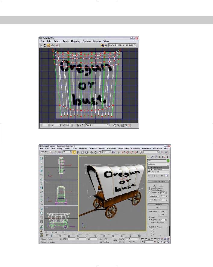
6.Then select all the remaining vertices and, with the Move tool, drag them to the center of the Edit UVWs window. Click and hold over the Scale tool, and select the Vertical Scale tool. Then drag in the window to vertically scale the vertices until they fit over the texture. Then horizontally scale the vertices slightly until the background texture is positioned within the wagon’s top.
Figure 23-10 shows the covered wagon with the mapped bitmap.
7.Press the M key to open the Material Editor. Click on the mapping button next to the Diffuse color, and double-click on the Bitmap type in the Material/Map Browser. Then select the Oregon or bust.tif file from the Chap 23 directory on the CD-ROM. Then apply this material to the covered wagon top. Click the Show Map in Viewport button (the small checkerboard cube icon) to see the map on the covered wagon.
Figure 23-11 shows the results of the new mapping coordinates.
Relaxing vertices
If your mapping coordinates are too tight and you’re having a tough time moving them, you can use the Relax tool (found in the Tools menu of the Edit UVW interface) to equally space the vertices. This tool works like the Relax modifier, pushing close vertices away and pulling far vertices closer together. Selecting this menu option opens the Relax Tool dialog box, shown in Figure 23-12. Amount is how aggressive the movement of the vertices are, and Iterations is the number of times to apply the relax algorithm. You also have options to Keep Boundary Points Fixed and Save Outer Corners.
Chapter 23 Controlling Mapping Coordinates |
649 |
Figure 23-10: The Edit UVWs interface lets you transform the mapping coordinates by moving vertices.
Figure 23-11: The position of covered wagon’s texture map has been set using the Unwrap UVW modifier.