

282 Part II Working with Objects
Using Pivot Points
An object’s pivot point is the center about which the object is rotated and scaled and about which most modifiers are applied. Pivot points are created by default when an object is created and are usually created at the center or base of an object. You can move and orient a pivot point in any direction, but repositioning the pivot cannot be animated. Pivot points exist for all objects, whether or not they are part of a hierarchy.
Caution |
Try to set your pivot points before animating any objects in your scene. If you relocate the |
|
pivot point after animation keys have been placed, all transformations are modified to use |
|
the new pivot point. |
Positioning pivot points
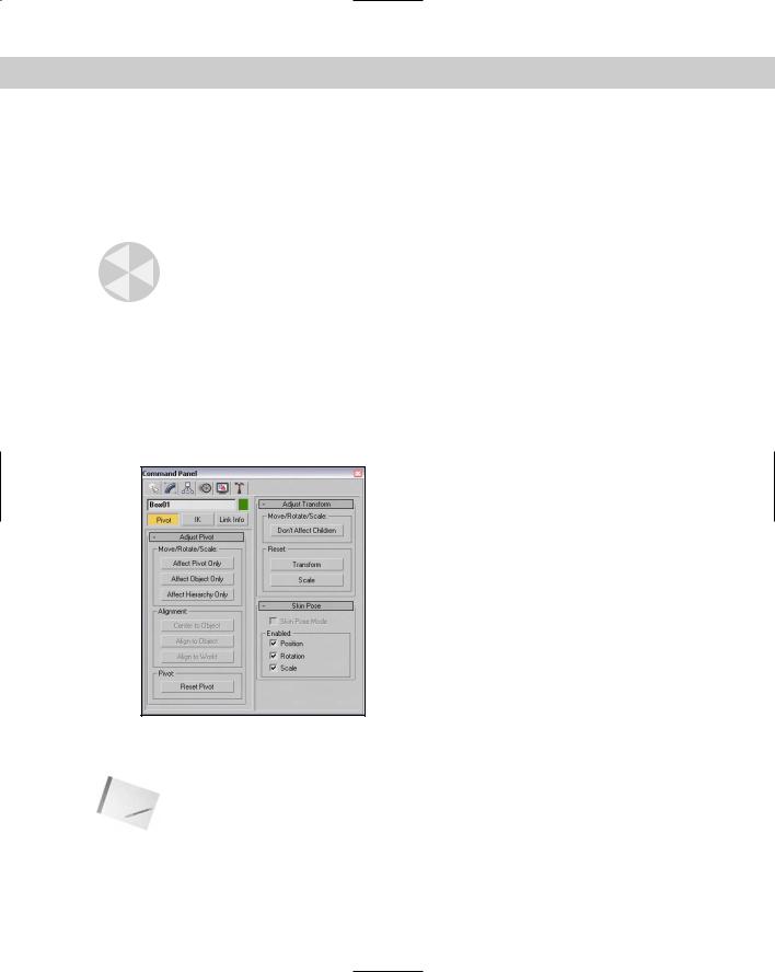
To move and orient a pivot point, open the Hierarchy panel in the Command Panel and click the Pivot button, shown in Figure 10-9. At the top of the Adjust Pivot rollout are three buttons; each button represents a different mode. The Affect Pivot Only mode makes the transformation buttons affect only the pivot point of the current selection. The object does not move. The Affect Object Only mode causes the object to be transformed, but not the pivot point; and the Affect Hierarchy Only mode allows an object’s links to be moved.
Figure 10-9: The Pivot button under the Hierarchy panel includes controls for affecting the pivot point.
Note Using the Scale transformation while one of these modes is selected alters the selected object but has no effect on the pivot point or the link.

Chapter 10 Transforming Objects—Translate, Rotate, and Scale |
283 |
Aligning pivot points
Below the mode buttons are three more buttons that are used to align the pivot points. These buttons are active only when a mode is selected. These buttons are Center to Object/Pivot, Align to Object/Pivot, and Align to World. The first two buttons switch between Object and Pivot, depending on the mode that is selected. You may select only one mode at a time. The button turns light blue when selected.
The Center to Object button moves the object so that its center is aligned with the pivot point, and the Center to Pivot button moves the pivot point so it is aligned with the object’s center. The Align to Object/Pivot button rotates the object or pivot point until the object’s Local Coordinate System and the pivot point are aligned. The Align to World button rotates either the object or the pivot to the World Coordinate System. For example, if the Affect Object Only mode is selected and the object is separated from the pivot point, clicking the Center to Pivot button moves the object so that its center is on the pivot point.
Under these three alignment buttons is another button labeled Reset Pivot, which you use to reset the pivot point to its original location.
|
Transform adjustments |
|
The Hierarchy panel of the Command Panel includes another useful rollout labeled Adjust |
|
Transform. This rollout, also shown in Figure 10-9, includes another mode that you can use |
|
with hierarchies of objects. Clicking the Don’t Affect Children button places you in a mode |
|
where any transformations of a linked hierarchy don’t affect the children. Typically, transfor- |
|
mations are applied to all linked children of a hierarchy, but this mode disables that. |
|
The Adjust Transform rollout also includes two buttons that allow you to reset the Local |
|
Coordinate System and scale percentage. These buttons set the current orientation of an |
|
object as the World coordinate or as the 100 percent standard. For example, if you select an |
|
object, move it 30 units to the left, and scale it to 200 percent, these values are displayed in |
|
the coordinate fields on the status bar. Clicking the Reset Transform and Reset Scale buttons |
|
resets these values to 0 and 100 percent. |
|
You use the Reset Scale button to reset the scale values for an object that has been scaled |
|
using non-uniform scaling. Non-uniform scaling can cause problems for child objects that |
|
inherit this type of scaling, such as shortening the links. The Reset Scale button can remedy |
|
these problems by resetting the parent’s scaling values. When the scale is reset, you won’t |
|
see a visible change to the object, but if you open the Scale Transform Type-In dialog box |
|
while the scale is being reset, you see the absolute local values being set back to 100 each. |
Tip |
If you are using an object that has been non-uniformly scaled, using Reset Scale before the |
|
item is linked saves you some headaches if you plan on using modifiers. |
Using the Reset XForm utility
You can also reset transform values using the Reset XForm utility. To use this utility, open the Utility panel and click the Reset XForm button, which is one of the default buttons. The benefit of this utility is that you can reset the transform values for multiple objects simultaneously. This happens by applying the XForm modifier to the objects. The rollout for this utility includes only a single button labeled Reset Selected.
284 Part II Working with Objects
Tutorial: A bee buzzing about a flower
By adjusting an object’s pivot point, you can control how the object is transformed about the scene. In this example, you animate a bee’s flapping wings by repositioning the wings’ pivot points. You then reposition the pivot point for the entire bee so it can rotate about the flower object.
To control how a bee rotates about a flower, follow these steps:
Cross-
Reference
1.Open the Buzzing bee.max file from the Chap 10 directory on the CD-ROM. This file includes a bee created from primitives and a flower model created by Zygote Media.
2.Click the bee object to select it and press Z to zoom in on it in all viewports. Click on the right wing, open the Hierarchy panel, and click on the Affect Pivot Only button. This displays the pivot point in the center of the wing. Drag the wing’s pivot point to the right in the Top viewport, and then down in the Front viewport until the pivot point is positioned where the wing contacts the body object. Then select the left wing and move its pivot to the position where it contacts the body object.
3.Click the Auto Key button (or press N) to enable animate mode and drag the Time Slider to frame 1. Then, with the Select and Rotate button (E), rotate the wing about its Z-axis until it is almost vertical in the Front viewport. Notice how the wing rotates about its new pivot point. Then drag the Time Slider to frame 2 and rotate the wing back to its original position. Click the Auto Key button again (N) to disable key mode.
4.Using the Track View, you can make these rotations repeat throughout the animation. Right-click on the wing object and select Curve Editor in the pop-up quadmenu that appears. This opens a Track View with the Rotation tracks selected. In the Track View, select Controller Out-of-Range Types to open the Param Out-of-Range Types dialog box, select the Loop option, and click OK. Then close the Track View.
Working with the Track View is beyond the scope of this chapter, but you can find more information on the Track View in Chapter 33, “Working with the Track View.”
5.Repeat steps 3 and 4 for the second wing object. Drag the Time Slider to see both wings flap for the entire animation.
6.Select all parts that make up the bee in the Top viewport, select Group Group, and name the object bee. Then select the bee and the flower in the Left viewport and press Z to zoom in on them.
7.With the bee group selected, click the Affect Pivot Only button in the Hierarchy panel and move the pivot point to the center of the flower in the Front viewport. Click the Affect Pivot Only button again to disable it.
8.Enable the Auto Key button (N) again and drag to frame 35. With the Select and Rotate button (E), rotate the bee in the Top viewport a third of the way around the flower. Drag the Time Slider to frame 70 and rotate the bee another third of the way. With the Time Slider at frame 100, complete the rotation. Click the Auto Key button again to display key mode.
9.Click the Play button (/) to see the final rotating bee.
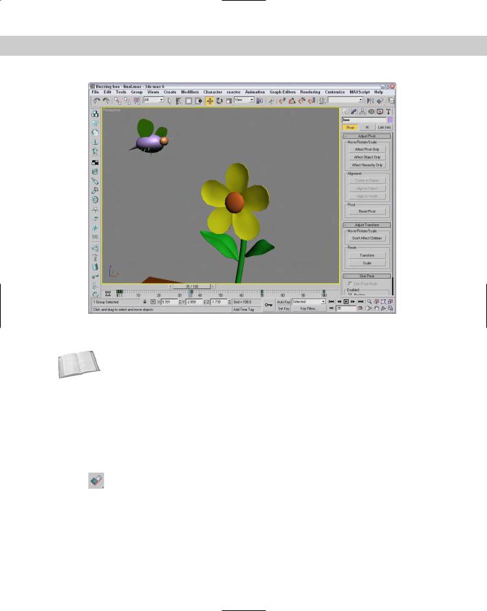
Figure 10-10 shows the bee as it moves around the flower where its pivot point is located.
Chapter 10 Transforming Objects—Translate, Rotate, and Scale |
285 |
Figure 10-10: By moving the pivot point of the bee, you can control how it spins about the flower.
Cross- |
To learn how to use the Skin Pose rollout at the bottom of the Hierarchy panel to set poses, |
Reference |
see Chapter 35, “Rigging Characters.” |
|
Using the Align Commands
The Align commands are an easy way to automatically transform objects. You can use these commands to line up object centers or edges, align normals and highlights, align to views and grids, and even line up cameras.
Aligning objects
Any object that you can transform, you can align, including lights, cameras, and Space Warps. After selecting the object to be aligned, click the Align flyout button on the main
toolbar or choose Tools Align (or press Alt+A). The cursor changes to the Align icon; now click a target object with which you want to align all the selected objects. Clicking the target object opens the Align Selection dialog box with the target object’s name displayed in the dialog box’s title, as shown in Figure 10-11.
286 Part II Working with Objects
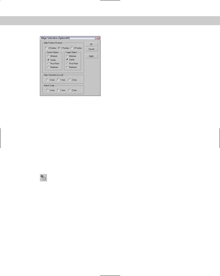
Figure 10-11: The Align Selection dialog box can align objects along any axes by their Minimum, Center, Pivot, or Maximum points.
The Align Selection dialog box includes settings for the X, Y, and Z positions to line up the Minimum, Center, Pivot Point, or Maximum dimensions for the selected or target object’s bounding box. As you change the settings in the dialog box, the objects reposition themselves, but the actual transformations don’t take place until you click the Apply button or the OK button.
Aligning normals
You can use the Normal Align command to line up points of the surface of two objects. A Normal vector is a projected line that extends from the center of a polygon face exactly perpendicular to the surface. When two Normal vectors are aligned, the objects are perfectly adjacent to one another. If the two objects are spheres, then they touch at only one point.
To align normals, you need to first select the object to move (this is the source object). Then choose Tools Normal Align or click the Normal Align flyout button under the
Align button on the main toolbar (or press Alt+N). The cursor changes to the Normal Align icon. Drag the cursor across the surface of the source object, and a blue arrow pointing out from the face center appears. Release the mouse when you’ve correctly pinpointed the position to align.
Next, click the target object, and drag the mouse to locate the target object’s align point. This is displayed as a green arrow. When you release the mouse, the source object moves to align the two points and the Normal Align dialog box appears, as shown in Figure 10-12.
When the objects are aligned, the two points match up exactly. The Normal Align dialog box lets you specify offset values that you can use to keep a distance between the two objects. You can also specify an Angle Offset, which is used to deviate the parallelism of the normals. The Flip Normal option aligns the objects so that their selected normals point in the same direction.
Objects without any faces, like Point Helper objects and Space Warps, use a vector between the origin and the Z-axis for normal alignment.

Chapter 10 Transforming Objects—Translate, Rotate, and Scale |
287 |
Figure 10-12: The Normal Align dialog box allows you to define offset values when aligning normals.
Tutorial: Aligning a kissing couple
Aligning normals positions two faces directly opposite one another, so what better way to practice this tool than to align two faces?
To connect the kissing couple using the Normal Align command, follow these steps:
1.Open the Kissing couple.max file from the Chap 10 directory on the CD-ROM.
This file includes two extruded shapes of a boy and a girl. The extruded shapes give us flat faces that are easy to align.
2.Select the girl shape, and choose the Tools Align Normals menu command (or press Alt+N). Then drag the cursor over the extruded shape until the blue vector points out from the front of the lips, as shown in Figure 10-13.
3.Then drag the cursor over the boy shape until the green vector points out from the front of the lips. Release the mouse, and the Normal Align dialog box appears. Enter a value of 5 in the Z-Axis Offset field, and click OK.
Figure 10-13 shows the resulting couple with normal aligned faces.
Figure 10-13: Using the Normal Align feature, you can align object faces.