

- •Preface
- •About This Book
- •Acknowledgments
- •Contents at a Glance
- •Contents
- •Relaxing at the Beach
- •Dressing the Scene
- •Animating Motion
- •Rendering the Final Animation
- •Summary
- •The Interface Elements
- •Using the Menus
- •Using the Toolbars
- •Using the Viewports
- •Using the Command Panel
- •Using the Lower Interface Bar Controls
- •Interacting with the Interface
- •Getting Help
- •Summary
- •Understanding 3D Space
- •Using the Viewport Navigation Controls
- •Configuring the Viewports
- •Working with Viewport Backgrounds
- •Summary
- •Working with Max Scene Files
- •Setting File Preferences
- •Importing and Exporting
- •Referencing External Objects
- •Using the File Utilities
- •Accessing File Information
- •Summary
- •Customizing Modify and Utility Panel Buttons
- •Working with Custom Interfaces
- •Configuring Paths
- •Selecting System Units
- •Setting Preferences
- •Summary
- •Creating Primitive Objects
- •Exploring the Primitive Object Types
- •Summary
- •Selecting Objects
- •Setting Object Properties
- •Hiding and Freezing Objects
- •Using Layers
- •Summary
- •Cloning Objects
- •Understanding Cloning Options
- •Mirroring Objects
- •Cloning over Time
- •Spacing Cloned Objects
- •Creating Arrays of Objects
- •Summary
- •Working with Groups
- •Building Assemblies
- •Building Links between Objects
- •Displaying Links and Hierarchies
- •Working with Linked Objects
- •Summary
- •Using the Schematic View Window
- •Working with Hierarchies
- •Setting Schematic View Preferences
- •Using List Views
- •Summary
- •Working with the Transformation Tools
- •Using Pivot Points
- •Using the Align Commands
- •Using Grids
- •Using Snap Options
- •Summary
- •Exploring the Modifier Stack
- •Exploring Modifier Types
- •Summary
- •Exploring the Modeling Types
- •Working with Subobjects
- •Modeling Helpers
- •Summary
- •Drawing in 2D
- •Editing Splines
- •Using Spline Modifiers
- •Summary
- •Creating Editable Mesh and Poly Objects
- •Editing Mesh Objects
- •Editing Poly Objects
- •Using Mesh Editing Modifiers
- •Summary
- •Introducing Patch Grids
- •Editing Patches
- •Using Modifiers on Patch Objects
- •Summary
- •Creating NURBS Curves and Surfaces
- •Editing NURBS
- •Working with NURBS
- •Summary
- •Morphing Objects
- •Creating Conform Objects
- •Creating a ShapeMerge Object
- •Creating a Terrain Object
- •Using the Mesher Object
- •Working with BlobMesh Objects
- •Creating a Scatter Object
- •Creating Connect Objects
- •Modeling with Boolean Objects
- •Creating a Loft Object
- •Summary
- •Understanding the Various Particle Systems
- •Creating a Particle System
- •Using the Spray and Snow Particle Systems
- •Using the Super Spray Particle System
- •Using the Blizzard Particle System
- •Using the PArray Particle System
- •Using the PCloud Particle System
- •Using Particle System Maps
- •Controlling Particles with Particle Flow
- •Summary
- •Understanding Material Properties
- •Working with the Material Editor
- •Using the Material/Map Browser
- •Using the Material/Map Navigator
- •Summary
- •Using the Standard Material
- •Using Shading Types
- •Accessing Other Parameters
- •Using External Tools
- •Summary
- •Using Compound Materials
- •Using Raytrace Materials
- •Using the Matte/Shadow Material
- •Using the DirectX 9 Shader
- •Applying Multiple Materials
- •Material Modifiers
- •Summary
- •Understanding Maps
- •Understanding Material Map Types
- •Using the Maps Rollout
- •Using the Map Path Utility
- •Using Map Instances
- •Summary
- •Mapping Modifiers
- •Using the Unwrap UVW modifier
- •Summary
- •Working with Cameras
- •Setting Camera Parameters
- •Summary
- •Using the Camera Tracker Utility
- •Summary
- •Using Multi-Pass Cameras
- •Creating Multi-Pass Camera Effects
- •Summary
- •Understanding the Basics of Lighting
- •Getting to Know the Light Types
- •Creating and Positioning Light Objects
- •Viewing a Scene from a Light
- •Altering Light Parameters
- •Working with Photometric Lights
- •Using the Sunlight and Daylight Systems
- •Using Volume Lights
- •Summary
- •Selecting Advanced Lighting
- •Using Local Advanced Lighting Settings
- •Tutorial: Excluding objects from light tracing
- •Summary
- •Understanding Radiosity
- •Using Local and Global Advanced Lighting Settings
- •Working with Advanced Lighting Materials
- •Using Lighting Analysis
- •Summary
- •Using the Time Controls
- •Working with Keys
- •Using the Track Bar
- •Viewing and Editing Key Values
- •Using the Motion Panel
- •Using Ghosting
- •Animating Objects
- •Working with Previews
- •Wiring Parameters
- •Animation Modifiers
- •Summary
- •Understanding Controller Types
- •Assigning Controllers
- •Setting Default Controllers
- •Examining the Various Controllers
- •Summary
- •Working with Expressions in Spinners
- •Understanding the Expression Controller Interface
- •Understanding Expression Elements
- •Using Expression Controllers
- •Summary
- •Learning the Track View Interface
- •Working with Keys
- •Editing Time
- •Editing Curves
- •Filtering Tracks
- •Working with Controllers
- •Synchronizing to a Sound Track
- •Summary
- •Understanding Your Character
- •Building Bodies
- •Summary
- •Building a Bones System
- •Using the Bone Tools
- •Using the Skin Modifier
- •Summary
- •Creating Characters
- •Working with Characters
- •Using Character Animation Techniques
- •Summary
- •Forward versus Inverse Kinematics
- •Creating an Inverse Kinematics System
- •Using the Various Inverse Kinematics Methods
- •Summary
- •Creating and Binding Space Warps
- •Understanding Space Warp Types
- •Combining Particle Systems with Space Warps
- •Summary
- •Understanding Dynamics
- •Using Dynamic Objects
- •Defining Dynamic Material Properties
- •Using Dynamic Space Warps
- •Using the Dynamics Utility
- •Using the Flex Modifier
- •Summary
- •Using reactor
- •Using reactor Collections
- •Creating reactor Objects
- •Calculating and Previewing a Simulation
- •Constraining Objects
- •reactor Troubleshooting
- •Summary
- •Understanding the Max Renderers
- •Previewing with ActiveShade
- •Render Parameters
- •Rendering Preferences
- •Creating VUE Files
- •Using the Rendered Frame Window
- •Using the RAM Player
- •Reviewing the Render Types
- •Using Command-Line Rendering
- •Creating Panoramic Images
- •Getting Printer Help
- •Creating an Environment
- •Summary
- •Creating Atmospheric Effects
- •Using the Fire Effect
- •Using the Fog Effect
- •Summary
- •Using Render Elements
- •Adding Render Effects
- •Creating Lens Effects
- •Using Other Render Effects
- •Summary
- •Using Raytrace Materials
- •Using a Raytrace Map
- •Enabling mental ray
- •Summary
- •Understanding Network Rendering
- •Network Requirements
- •Setting up a Network Rendering System
- •Starting the Network Rendering System
- •Configuring the Network Manager and Servers
- •Logging Errors
- •Using the Monitor
- •Setting up Batch Rendering
- •Summary
- •Compositing with Photoshop
- •Video Editing with Premiere
- •Video Compositing with After Effects
- •Introducing Combustion
- •Using Other Compositing Solutions
- •Summary
- •Completing Post-Production with the Video Post Interface
- •Working with Sequences
- •Adding and Editing Events
- •Working with Ranges
- •Working with Lens Effects Filters
- •Summary
- •What Is MAXScript?
- •MAXScript Tools
- •Setting MAXScript Preferences
- •Types of Scripts
- •Writing Your Own MAXScripts
- •Learning the Visual MAXScript Editor Interface
- •Laying Out a Rollout
- •Summary
- •Working with Plug-Ins
- •Locating Plug-Ins
- •Summary
- •Low-Res Modeling
- •Using Channels
- •Using Vertex Colors
- •Rendering to a Texture
- •Summary
- •Max and Architecture
- •Using AEC Objects
- •Using Architectural materials
- •Summary
- •Tutorial: Creating Icy Geometry with BlobMesh
- •Tutorial: Using Caustic Photons to Create a Disco Ball
- •Summary
- •mental ray Rendering System
- •Particle Flow
- •reactor 2.0
- •Schematic View
- •BlobMesh
- •Spline and Patch Features
- •Import and Export
- •Shell Modifier
- •Vertex Paint and Channel Info
- •Architectural Primitives and Materials
- •Minor Improvements
- •Choosing an Operating System
- •Hardware Requirements
- •Installing 3ds max 6
- •Authorizing the Software
- •Setting the Display Driver
- •Updating Max
- •Moving Max to Another Computer
- •Using Keyboard Shortcuts
- •Using the Hotkey Map
- •Main Interface Shortcuts
- •Dialog Box Shortcuts
- •Miscellaneous Shortcuts
- •System Requirements
- •Using the CDs with Windows
- •What’s on the CDs
- •Troubleshooting
- •Index
Chapter 27 Basic Lighting Techniques 699
For the Advanced Raytraced Shadows options, the rollout includes many more options, including Simple, 1-Pass, or 2-Pass Anti-aliasing. This rollout also includes the same quality values found in the Area Shadows rollout.
Note |
Depending on the number of objects in your scene, shadows can take a long time to render. |
|
Enabling raytraced shadows for a complex scene can greatly increase the render time. |
Optimizing lights
If you select either the Area Shadows or the Advanced Raytracing Shadows types, then a separate Optimizations rollout appears. This rollout includes settings that help speed up the shadow rendering process. Using this rollout, you can enable Transparent Shadows. You
can also specify a color that is used at the Anti-aliasing Threshold. You can also turn off antialiasing for materials that have SuperSampling or Reflection/Refraction enabled. Or you can have the shadow renderer skip coplanar faces with a given threshold.
Manipulating Hotspot and Falloff cones
When the Select and Manipulate mode is enabled on the main toolbar, the end of the Hotspot and Falloff cones appear green for a selected spotlight. When you move the mouse over these lines, the lines turn red, allowing you to drag the lines and make the Hotspot and/or Falloff angle values greater. These manipulators provide visual feedback as you resize the spotlight cone.
Working with Photometric Lights
The standard Max lights rely on parameters like Multiplier, Decay, and Attenuation, but the last time I was in the hardware store looking for a light bulb with a 2.5 Multiplier value, I was disappointed. Lights in the real world have their own set of measurements that define the type of light that is produced. Photometric lights are lights that are based on real-world light measurement values such as Intensity in Lumens and temperatures in degrees Kelvin.
If you select the Lights menu or the Lights category in the Create panel, you’ll notice a submenu called Standard, which accesses the basic standard lights. Another submenu of lights is called Photometric. Photometric lights are based on photometric values, which are the values of light energy.
The lights found in this subcategory include Target Point, Target Linear, Target Area, Free Point, Free Linear, Free Area, IES Sun, and IES Sky.
Target and Free photometric lights
Target photometric lights come in three shapes — Point, Linear, and Area. Selecting a different shaped light causes the light to be spread over a wider area, so in most cases, the Point light results in the brightest intensity. Figure 27-10 shows the three different shapes. The General Parameters rollout includes a drop-down list that you can use to change the light shape and specify whether it is targeted or not.
700 Part VI Lighting
Figure 27-10: Photometric lights can be Point, Linear, or Area (left to right).
The gizmo for a point photometric lights is a simple sphere. The gizmo for linear lights is a sphere and a line, and the gizmo for area lights is a sphere and a rectangle. For targeted lights, the target extends from the gizmo to the target. The dimensions for the light are in the Linear (Area) Light Parameters rollout.
Most of the light rollouts are the same as those for the standard lights, but the Intensity/ Color/Distribution rollout, as shown in Figure 27-11, is unique.
Figure 27-11: The Intensity/Color/Distribution rollout for photometric lights uses real-world intensity values.
Distribution options
The Distribution options are listed in the drop-down list at the top of the rollout. The options include Isotropic, Spotlight, and Web for the Point lights and Diffuse and Web for the Linear and Area lights.
The Isotropic and Diffuse options are the same, but they work for different light shapes. They provide even light in all directions from the light. The light gradually becomes weaker as the distance from the light increases.
The Spotlight option is only available for Point lights. It concentrates the light energy into a cone that emits from the light. This cone of light energy is directional and can be controlled with the Hotspot and Falloff values.
The Web option is a custom option that lets you open a separate file describing the light’s emission pattern. These files have the .IES, .CIBSE, or .LTLI extensions. Light manufacturers have this data for the various real-world lights that they sell. You load these files using the Web File button found in the Web Parameters rollout. You can also specify the X-, Y-, and Z-axis rotation values.

Chapter 27 Basic Lighting Techniques 701
Color options
The Color section of the Intensity/Color/Distribution rollout includes two ways to specify a light’s color. The first is a drop-down list of options. The options found in the list include standard real-world light types such as Cool White, Mercury, and Halogen. Table 27-2 lists each of these types and its approximate color.
|
Table 27-2: Photometric Light Colors |
|
|
Light Type |
Color |
|
|
Cool White |
Yellow-white |
Custom |
Any color |
D65White |
White |
Daylight Fluorescent |
Mostly white with a slight gray tint |
Fluorescent |
Yellow-white |
Halogen |
Beige-white |
High Pressure Sodium |
Tan |
Incandescent |
Beige-white |
Low Pressure Sodium |
Light orange |
Mercury |
Green-white |
Metal Halide |
Yellow-white |
Phosphor Mercury |
Light green |
Quartz |
Yellow-white |
White Fluorescent |
Yellow-white |
Xenon |
White |
|
|
In addition to a list of available light types, you can specify a color based on temperature expressed in degrees Kelvin. Temperature-based colors run from a cool 1,000 degrees, which is a mauve-pink color, through light yellow and white (at 6,000 degrees Kelvin) to a hot light blue at 20,000 degrees Kelvin.
You also can set a Filter Color using the color swatch found in this section. The Filter Color simulates the color caused by some colored cellophane placed in front of the light.
Intensity options
The Intensity options can be specified in Lumens, Candelas, or Lux at a given distance. Light manufacturers have this information available. You also can specify a Multiplier value, which determines how effective the light is.
702 Part VI Lighting
IES photometric lights
The Photometric light subcategory also includes two additional lights — IES Sky and IES Sun. The IES Sky light simulates ambient light. In the Sky Parameters rollout, you can specify the sky as Clear, Partly Cloudy, or Cloudy. These same parameters are also found in the Daylight system.
The IES Sun light simulates the bright outdoor light of the sun. It is a single light with a great deal of power. It can be targeted and can have an Intensity value of 50 billion lux. This type of light is very valuable in architecture renderings.
Using the Sunlight and Daylight Systems
The Sunlight and Daylight systems, accessed through the Systems category of the Create panel, create a light that simulates the sun for a specific geographic location, date, time, and compass direction.
Note |
The Daylight system can be created using the Create Lights menu or the Create Systems |
|
menu, but the Sunlight system cannot be created using a menu. |
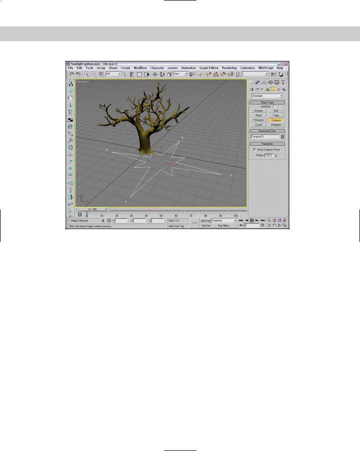
To create either of these systems, open the Create panel and click the Systems category button. Then click the Sunlight (or Daylight) button, and drag the mouse in a viewport. A Compass helper object appears. Click again to create a Direct light (or Skylight) representing the sun. Figure 27-12 shows the Compass helper created as part of the Sunlight system. The main difference between these two systems is that the Sunlight system uses a Directional light and the Daylight system uses a Skylight.
Using the Compass helper
The Compass helper is useful when working with a Sunlight system. It can be used to define the map directions of North, East, South, and West. The Sunlight system uses these directions to orient the system light. This helper is not renderable and is created automatically when you define a sunlight object.
After you create a Sunlight system, you can alter the sun’s position by transforming the Compass helper. Doing so causes the direct light object to move appropriately. You cannot transform the Direct light by itself.
Note |
You can change the settings for the light that is the sun by selecting the light from the Select |
|
by Name dialog box and opening the Modify panel. The sunlight object uses raytraced shad- |
|
ows by default. |
Understanding Azimuth and Altitude
Azimuth and Altitude are two values that help define the location of the sun in the sky. Both are measured in degrees. Azimuth refers to the compass direction and can range from 0 to 360, with 0 degrees being North, 90 degrees being East, 180 degrees being South, and 270 degrees being West. Altitude is the angle in degrees between the sun and the horizon. This value ranges typically between 0 and 90, with 0 degrees being either sunrise or sunset and 90 when the sun is directly overhead.
Chapter 27 Basic Lighting Techniques 703
Figure 27-12: The Compass helper provides an orientation for positioning the sun in a Sunlight system.
Specifying date and time
The Time section of the Control Parameters rollout lets you define a time and date. The Time Zone value is the number of offset hours for your current time zone. You can also set the time to be converted for Daylight Saving Time.
Specifying location
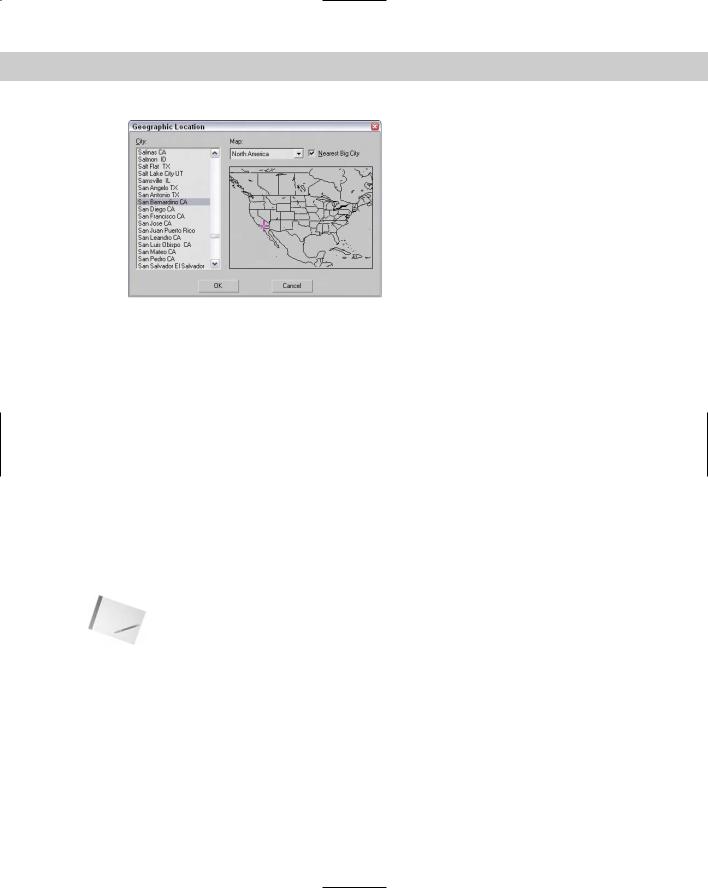
Clicking the Get Location button in the Control Parameters rollout opens the Geographic Location dialog box, shown in Figure 27-13, which displays a map or a list of cities. Selecting a location using this dialog box automatically updates the Latitude and Longitude values. In addition to the Get Location button, you can enter Latitude and Longitude values directly in the Control Parameters rollout.
The Daylight system also includes an option to set the Sky value from Clear, Partly Cloudy, to Cloudy.
Tutorial: Animating a day in 20 seconds
You can animate the Sunlight system to show an entire day from sunrise to sundown in a short number of frames. In this tutorial, we focus on an old tree positioned somewhere in Phoenix, Arizona, on Christmas. The tree certainly won’t move, but watch its shadows.
704 Part VI Lighting
Figure 27-13: The Geographic Location dialog box lets you specify where you want to use the Sunlight system. You have many different cities to choose from.
To use the Sunlight system to animate shadows, follow these steps:
1.Open the Sunlight system.max file from the Chap 27 directory on the CD-ROM. This file includes a tree mesh created by Zygote.
2.Add a Sunlight System by selecting the Systems category in the Create panel and clicking the Sunlight button. Then drag in the Top view to create the Compass helper, and click again to create the light. In the Control Parameters, enter 12/25 and the current year for the Date and an early morning hour for the Time.
3.Click the Get Location button, locate Phoenix in the Cities list, and click OK. Rotate the compass helper in the Top view so that north is pointing toward the top of the viewport.
4.Click the Auto Key button (or press the N key), and move the Time slider to frame 100.
5.In the Control Parameters rollout, change the Time value to an evening hour. Then click the Auto Key button (N) again to disable animation mode.
Note |
You can tell when the sun comes up and goes down by looking at the Altitude value for each |
|
hour. A negative Altitude value indicates that the sun is below the horizon. |
Figure 27-14 shows a snapshot of this quick day. The upper-left image shows the animation at frame 20, the upper-right image shows it at frame 40, the lower-left image shows it at frame 60, and the final image shows it at frame 80.