

- •Preface
- •About This Book
- •Acknowledgments
- •Contents at a Glance
- •Contents
- •Relaxing at the Beach
- •Dressing the Scene
- •Animating Motion
- •Rendering the Final Animation
- •Summary
- •The Interface Elements
- •Using the Menus
- •Using the Toolbars
- •Using the Viewports
- •Using the Command Panel
- •Using the Lower Interface Bar Controls
- •Interacting with the Interface
- •Getting Help
- •Summary
- •Understanding 3D Space
- •Using the Viewport Navigation Controls
- •Configuring the Viewports
- •Working with Viewport Backgrounds
- •Summary
- •Working with Max Scene Files
- •Setting File Preferences
- •Importing and Exporting
- •Referencing External Objects
- •Using the File Utilities
- •Accessing File Information
- •Summary
- •Customizing Modify and Utility Panel Buttons
- •Working with Custom Interfaces
- •Configuring Paths
- •Selecting System Units
- •Setting Preferences
- •Summary
- •Creating Primitive Objects
- •Exploring the Primitive Object Types
- •Summary
- •Selecting Objects
- •Setting Object Properties
- •Hiding and Freezing Objects
- •Using Layers
- •Summary
- •Cloning Objects
- •Understanding Cloning Options
- •Mirroring Objects
- •Cloning over Time
- •Spacing Cloned Objects
- •Creating Arrays of Objects
- •Summary
- •Working with Groups
- •Building Assemblies
- •Building Links between Objects
- •Displaying Links and Hierarchies
- •Working with Linked Objects
- •Summary
- •Using the Schematic View Window
- •Working with Hierarchies
- •Setting Schematic View Preferences
- •Using List Views
- •Summary
- •Working with the Transformation Tools
- •Using Pivot Points
- •Using the Align Commands
- •Using Grids
- •Using Snap Options
- •Summary
- •Exploring the Modifier Stack
- •Exploring Modifier Types
- •Summary
- •Exploring the Modeling Types
- •Working with Subobjects
- •Modeling Helpers
- •Summary
- •Drawing in 2D
- •Editing Splines
- •Using Spline Modifiers
- •Summary
- •Creating Editable Mesh and Poly Objects
- •Editing Mesh Objects
- •Editing Poly Objects
- •Using Mesh Editing Modifiers
- •Summary
- •Introducing Patch Grids
- •Editing Patches
- •Using Modifiers on Patch Objects
- •Summary
- •Creating NURBS Curves and Surfaces
- •Editing NURBS
- •Working with NURBS
- •Summary
- •Morphing Objects
- •Creating Conform Objects
- •Creating a ShapeMerge Object
- •Creating a Terrain Object
- •Using the Mesher Object
- •Working with BlobMesh Objects
- •Creating a Scatter Object
- •Creating Connect Objects
- •Modeling with Boolean Objects
- •Creating a Loft Object
- •Summary
- •Understanding the Various Particle Systems
- •Creating a Particle System
- •Using the Spray and Snow Particle Systems
- •Using the Super Spray Particle System
- •Using the Blizzard Particle System
- •Using the PArray Particle System
- •Using the PCloud Particle System
- •Using Particle System Maps
- •Controlling Particles with Particle Flow
- •Summary
- •Understanding Material Properties
- •Working with the Material Editor
- •Using the Material/Map Browser
- •Using the Material/Map Navigator
- •Summary
- •Using the Standard Material
- •Using Shading Types
- •Accessing Other Parameters
- •Using External Tools
- •Summary
- •Using Compound Materials
- •Using Raytrace Materials
- •Using the Matte/Shadow Material
- •Using the DirectX 9 Shader
- •Applying Multiple Materials
- •Material Modifiers
- •Summary
- •Understanding Maps
- •Understanding Material Map Types
- •Using the Maps Rollout
- •Using the Map Path Utility
- •Using Map Instances
- •Summary
- •Mapping Modifiers
- •Using the Unwrap UVW modifier
- •Summary
- •Working with Cameras
- •Setting Camera Parameters
- •Summary
- •Using the Camera Tracker Utility
- •Summary
- •Using Multi-Pass Cameras
- •Creating Multi-Pass Camera Effects
- •Summary
- •Understanding the Basics of Lighting
- •Getting to Know the Light Types
- •Creating and Positioning Light Objects
- •Viewing a Scene from a Light
- •Altering Light Parameters
- •Working with Photometric Lights
- •Using the Sunlight and Daylight Systems
- •Using Volume Lights
- •Summary
- •Selecting Advanced Lighting
- •Using Local Advanced Lighting Settings
- •Tutorial: Excluding objects from light tracing
- •Summary
- •Understanding Radiosity
- •Using Local and Global Advanced Lighting Settings
- •Working with Advanced Lighting Materials
- •Using Lighting Analysis
- •Summary
- •Using the Time Controls
- •Working with Keys
- •Using the Track Bar
- •Viewing and Editing Key Values
- •Using the Motion Panel
- •Using Ghosting
- •Animating Objects
- •Working with Previews
- •Wiring Parameters
- •Animation Modifiers
- •Summary
- •Understanding Controller Types
- •Assigning Controllers
- •Setting Default Controllers
- •Examining the Various Controllers
- •Summary
- •Working with Expressions in Spinners
- •Understanding the Expression Controller Interface
- •Understanding Expression Elements
- •Using Expression Controllers
- •Summary
- •Learning the Track View Interface
- •Working with Keys
- •Editing Time
- •Editing Curves
- •Filtering Tracks
- •Working with Controllers
- •Synchronizing to a Sound Track
- •Summary
- •Understanding Your Character
- •Building Bodies
- •Summary
- •Building a Bones System
- •Using the Bone Tools
- •Using the Skin Modifier
- •Summary
- •Creating Characters
- •Working with Characters
- •Using Character Animation Techniques
- •Summary
- •Forward versus Inverse Kinematics
- •Creating an Inverse Kinematics System
- •Using the Various Inverse Kinematics Methods
- •Summary
- •Creating and Binding Space Warps
- •Understanding Space Warp Types
- •Combining Particle Systems with Space Warps
- •Summary
- •Understanding Dynamics
- •Using Dynamic Objects
- •Defining Dynamic Material Properties
- •Using Dynamic Space Warps
- •Using the Dynamics Utility
- •Using the Flex Modifier
- •Summary
- •Using reactor
- •Using reactor Collections
- •Creating reactor Objects
- •Calculating and Previewing a Simulation
- •Constraining Objects
- •reactor Troubleshooting
- •Summary
- •Understanding the Max Renderers
- •Previewing with ActiveShade
- •Render Parameters
- •Rendering Preferences
- •Creating VUE Files
- •Using the Rendered Frame Window
- •Using the RAM Player
- •Reviewing the Render Types
- •Using Command-Line Rendering
- •Creating Panoramic Images
- •Getting Printer Help
- •Creating an Environment
- •Summary
- •Creating Atmospheric Effects
- •Using the Fire Effect
- •Using the Fog Effect
- •Summary
- •Using Render Elements
- •Adding Render Effects
- •Creating Lens Effects
- •Using Other Render Effects
- •Summary
- •Using Raytrace Materials
- •Using a Raytrace Map
- •Enabling mental ray
- •Summary
- •Understanding Network Rendering
- •Network Requirements
- •Setting up a Network Rendering System
- •Starting the Network Rendering System
- •Configuring the Network Manager and Servers
- •Logging Errors
- •Using the Monitor
- •Setting up Batch Rendering
- •Summary
- •Compositing with Photoshop
- •Video Editing with Premiere
- •Video Compositing with After Effects
- •Introducing Combustion
- •Using Other Compositing Solutions
- •Summary
- •Completing Post-Production with the Video Post Interface
- •Working with Sequences
- •Adding and Editing Events
- •Working with Ranges
- •Working with Lens Effects Filters
- •Summary
- •What Is MAXScript?
- •MAXScript Tools
- •Setting MAXScript Preferences
- •Types of Scripts
- •Writing Your Own MAXScripts
- •Learning the Visual MAXScript Editor Interface
- •Laying Out a Rollout
- •Summary
- •Working with Plug-Ins
- •Locating Plug-Ins
- •Summary
- •Low-Res Modeling
- •Using Channels
- •Using Vertex Colors
- •Rendering to a Texture
- •Summary
- •Max and Architecture
- •Using AEC Objects
- •Using Architectural materials
- •Summary
- •Tutorial: Creating Icy Geometry with BlobMesh
- •Tutorial: Using Caustic Photons to Create a Disco Ball
- •Summary
- •mental ray Rendering System
- •Particle Flow
- •reactor 2.0
- •Schematic View
- •BlobMesh
- •Spline and Patch Features
- •Import and Export
- •Shell Modifier
- •Vertex Paint and Channel Info
- •Architectural Primitives and Materials
- •Minor Improvements
- •Choosing an Operating System
- •Hardware Requirements
- •Installing 3ds max 6
- •Authorizing the Software
- •Setting the Display Driver
- •Updating Max
- •Moving Max to Another Computer
- •Using Keyboard Shortcuts
- •Using the Hotkey Map
- •Main Interface Shortcuts
- •Dialog Box Shortcuts
- •Miscellaneous Shortcuts
- •System Requirements
- •Using the CDs with Windows
- •What’s on the CDs
- •Troubleshooting
- •Index

392 Part III Modeling
Table 14-1 (continued)
Feature |
Editable Mesh |
Editable Poly |
|
|
|
Extrude Along Spline |
|
X* |
Slice Plane/Slice |
X |
X |
QuickSlice |
|
X |
Cut |
X |
X |
Weld Selected/Target |
X |
X* |
Msmooth |
|
X* |
Tessellate |
X |
X* |
Explode |
X |
|
Remove Isolated Vertices |
X |
X |
Remove Unused Map Vertices |
|
X |
Select Open Edges |
X |
|
Create Shape from Edges |
X |
X |
View Align/Grid Align |
X |
X |
Make Planar |
X |
X |
Collapse |
X |
X |
Surface Properties |
X |
X |
Vertex Colors |
X |
X |
Subdivision |
X |
X |
Smoothing Groups |
X |
X |
|
|
|
Tip |
From Table 14-1, you can see the benefit of the Editable Poly object. They have many more |
|
unique features and greater flexibility. Most of the new modeling enhancements are found in |
|
the Editable Poly objects. For serious modelers, Editable Polys is clearly the preferred model- |
|
ing type. |
Editing Mesh Objects
After an object has been converted to an Editable Mesh or an Editable Poly, you can alter its shape by applying modifiers, or you can work with the mesh subobjects. You can find the editing features for these objects in the Modify panel.

Chapter 14 Working with Meshes and Polys 393
Editable Mesh subobjects modes
Before you can edit Mesh subobjects, you must select them. To select a subobject mode, select Editable Mesh in the Modifier Stack, click the small plus sign to its left to display a hierarchy of subobjects, and then click the subobject type with which you want to work. Another way to select a subobject type is to click on the appropriate subobject button in the Selection rollout. The subobject button in the Selection rollout and the subobject listed in the Modifier Stack both turn bright yellow when selected. You can also type a number 1–5 to enter subobject mode with 1 for Vertex, 2 for Edge, 3 for Face, 4 for Polgyon, and 5 for Element.
To exit subobject edit mode, click the subobject button (displayed in yellow) again. Remember, you must exit this mode before you can select another object.
Note Selected subobject edges appear in the viewports in red to distinguish them from edges of the selected object, which appear white when displayed as wireframes.
After you’re in a subobject mode, you can click on a subobject (or drag over an area to select multiple subobjects) to select it and edit the subobject using the transformation buttons on the main toolbar. You can transform subobjects just like other objects.
Cross- |
For more information on transforming objects, see Chapter 10, “Transforming Objects — |
Reference |
Translate, Rotate, and Scale.” |
|
You can select multiple subobjects at the same time by dragging an outline over them. You can also select multiple subobjects by holding down the Ctrl key while clicking them. The Ctrl key can also deselect selected subobjects while maintaining the rest of the selection. Holding down the Alt key removes any selected vertices from the current selection set.
Tip If you select several subobjects in one subobject mode, you can keep the same selection when moving to another subobject mode by holding down the Alt key. For example, if you select a group of vertices and, while holding down the Alt key, you click on the Polygon button (this works only for the subobject buttons in the Selection rollout), then all Polygon subobjects connected to the selected vertices are selected.
With one of the transform buttons selected, hold down the Shift key while clicking and dragging on a subobject to clone it. During cloning, the Clone Part of Mesh dialog box appears, enabling you to Clone to Object or Clone to Element. Using the Clone to Object option makes the selection an entirely new object, and you are able to give the new object a name. If the Clone to Element option is selected, the clone remains part of the existing object but is a new element within that object.
Selection rollout
The Selection rollout includes options for selecting subobjects. The By Vertex option is available in all but the Vertex subobject mode. It requires that you click a vertex in order to select an edge, face, polygon, or element. It selects all edges and faces that are connected to a vertex when the vertex is selected. The Ignore Backfacing option selects only those subobjects with normals pointing toward the current viewport. For example, if you are trying to select some faces on a sphere, only the faces on the side closest to you are selected. If this option is off, then faces on both sides of the sphere are selected. This option is helpful if many subobjects are on top of one another in the viewport.

394 Part III Modeling
Tip |
The select commands in the Edit menu also works with subobjects. For example, in Vertex |
|
subobject mode, you can select Edit Select All (or press Ctrl+A) to select all vertices. |
|
The Ignore Visible Edges option is active only in Polygon subobject mode. This button |
|
enables you to select all the coplanar polygons, as determined by the Planar Threshold value |
|
regardless of their visible boundaries. The Planar Threshold is defined as the angle between |
|
the normals of adjacent polygons. For example, if you have a terrain mesh with a smooth, flat |
|
lake area in its middle, you can select the entire lake area if you set the Planar Threshold to 0 |
|
and click the lake. If the Ignore Visible Edges option is not selected, the selection is limited to |
|
the visible edges of the polygon that is clicked. |
|
In all subobject modes except for Edge, you can select to Show Normals and set a Scale value. |
|
Normals are vectors that extend outward perpendicular to the surface of an object. Using this |
|
option, you can determine which way a subobject is facing, which can affect how the object is |
|
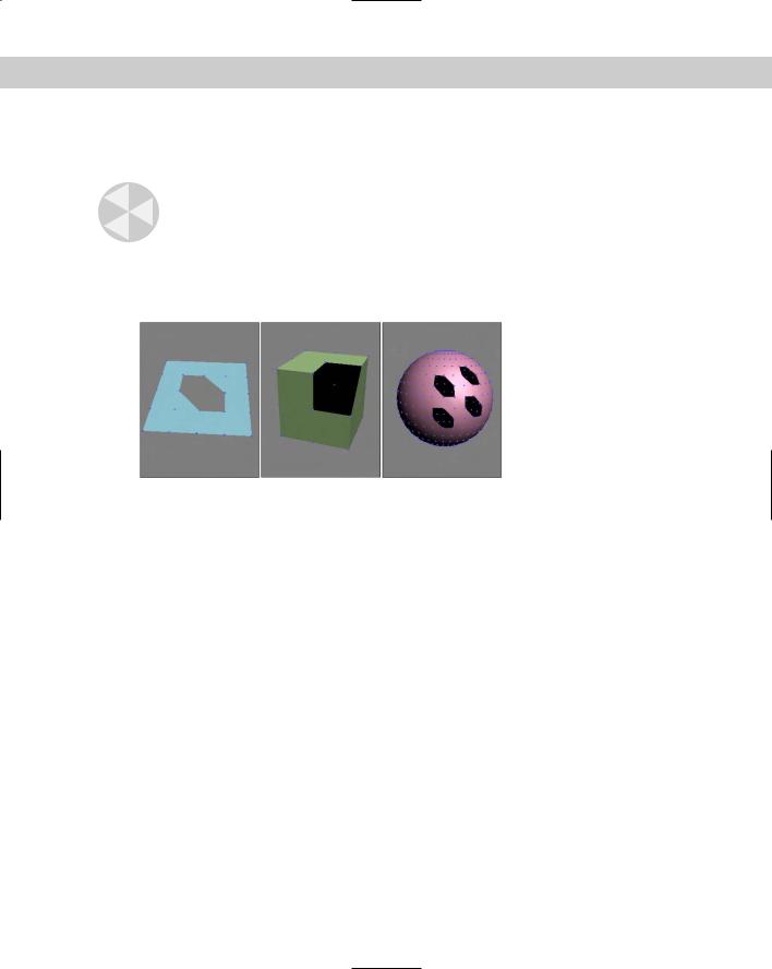
smoothed and lighted. Figure 14-1 shows a Plane, a Box, and a Sphere object, each of which |
|
has been converted to an Editable Mesh with all faces selected in Face subobject mode with |
|
the Show Normals option selected. |
Figure 14-1: The Show Normals option shows the normal vectors for each face in a sphere.
The Hide button hides the selected subobjects. You can make hidden objects visible again with the Unhide All button.
After selecting several subobjects, you can create a named selection set by typing a name in the Name Selection Sets drop-down list in the main toolbar. You can then copy and paste these selection sets onto other shapes.
At the bottom of the Selection rollout is the Selection Information, which is a text line that automatically displays the number and subobject type of selected items.
Cross- The Soft Selection rollout allows you to alter adjacent non-selected subobjects when Reference selected subobjects are moved, creating a smooth transition. For the details on this rollout,
see Chapter 12, “Modeling Basics.”

Chapter 14 Working with Meshes and Polys 395
Edit Geometry rollout
Much of the power of editing meshes is contained within the Edit Geometry rollout. Features contained here include, among many others, the ability to create new subobjects, attach subobjects to the mesh, weld vertices, chamfer vertices, slice, explode, and align. Some Edit Geometry buttons are disabled depending on the subobject mode that you select. The following features are enabled for the Editable Mesh object before you enter a subobject mode.
Attach
The Attach button is available with all subobject modes and even when you are not in subobject mode. Use the Attach button to add objects to the current Editable Mesh objects. You can add primitives, splines, patch objects, and other mesh objects. Any object that is attached to a mesh object is automatically converted into an editable mesh and inherits the object color of the object to which it is attached. Any objects that are added to a mesh object can be selected individually using the Element subobject mode.
Caution |
If you attach an object that is smoothed using NURMS, the NURMS are lost when the |
|
object is attached. |
To use this feature, select the main object and click the Attach button. Move the mouse over the object to be attached; the cursor changes over acceptable objects. Click the object to select it. Click the Attach button again or right-click in the viewport to exit Attach mode.
Note If the object that you click to attach already has a material applied that is different from the current Editable Mesh object, then a dialog box appears giving you options to Match Material IDs to Material, Match Material to Material IDs, or Do Not Modify Material IDs or Material. Materials and Material IDs are discussed in more detail in Chapter 19, “Exploring the Material Editor.”
Clicking the Attach List button opens the Attach List dialog box [which looks just like the Select Objects (H) dialog box] where you can select from a list of all the objects to attach. The list contains only objects that you can attach.
Note When you enter a subobject mode, the Attach List button changes to a Detach button for mesh objects.
Attaching objects is different from grouping objects because all attached objects act as a single object with the same object color, name, and transforms. You can access individual attached objects using the Element subobject mode.
Explode
The Explode button also can be used outside of all subobject modes and with the Face, Polygon, and Element subobject modes. It is the opposite of the Attach button and can be used to separate all selected faces or polygons into individual objects or elements. The spinner to the right sets the angle value between the faces normals to include in this operation. If the Objects option is selected, the Explode to Objects dialog box appears, enabling you to name the object.

396 Part III Modeling
Remove Isolated Vertices
The Remove Isolated Vertices button can be used at any time and in any subobject mode. It automatically deletes all isolated vertices associated with a mesh object, selected or not. Isolated vertices can result from deleting a face, or they could be inserted with the Create button and never connected. This helpful feature cleans up a mesh before applying any modifiers. Some modifiers cannot be applied if isolated vertices are part of the mesh.
View and Grid Align
The View and Grid Align buttons move and orient all selected vertices to the current active viewport or to the current construction grid. These buttons can also be used in all subobject modes. This causes all the selected face normals to point directly at the grid or view.
Subdivision Displacement
The Surface Properties rollout includes an option to enable Subdivision Displacement. This causes the mesh surface to be subdivided as needed when a displacement map is applied to it. A displacement map is a texture map that defines the valleys and peaks of the mesh to which it is applied, with dark areas being push down and light areas being pushed up. If the displacement map has a gradient, then it must subdivide the surface in order to represent the climb in elevation.
Cross- |
More on displacement maps is covered in Chapter 22, “Adding Material Details with Maps.” |
Reference |
|
The Split Mesh option allows the mesh faces to be split during the subdivision process. The Low, Medium, and High presets will control the Edge, Distance, and Angle values below or you could manually set the number of Steps to use during subdivision. You can also select one of the Subdivision Methods — Regular, Spatial, Curvature, or Spatial and Curvature. This feature is only available when none of the subobject modes are enabled.
Editing vertices
When working with Editable Mesh objects, after you select Vertex subobject mode (keyboard shortcut, 1) and select vertices, you can transform them using the transform buttons on the main toolbar. When you move the vertices around, the connected mesh edges will follow.
Create
The Create button lets you add new vertices to a mesh object. To create a new vertex, click the Create button to enter Create mode. You can then click where you want the new vertex to be located. Create mode works for all mesh subobject types except edges.
Caution |
Be aware that creating a vertex doesn’t add it to any of the edges, but the Create button in |
|
Edge subobject mode can connect edges to these isolated vertices. |
Chapter 14 Working with Meshes and Polys 397
Delete
The Delete button lets you delete the selected vertices. To use this button, select a vertex or vertices to delete and click the Delete button. This button works for all the subobject types.
Caution |
Deleting a vertex also deletes all faces and their edges connected to that vertex. This deletion |
|
can cause holes in the geometry and cause problems with many modifiers. |
Figure 14-2 shows Editable Mesh Plane, Box, and Sphere objects with several deleted vertices. In each example, the deleted vertex has created a hole in the geometry. You can see the back inside of the objects or straight through them.
Figure 14-2: Deleting vertices also deletes the adjoining faces and edges.
Detach
Use the Detach button to separate the selected subobjects from the rest of the object. To use this button, select the subobject and click the Detach button. The Detach dialog box opens, enabling you to name the new detached subobject. You also have the options to Detach to Element or to Detach as Clone. All subobject modes except Edge have a Detach option. This button appears in place of the Attach List button in all subobject modes.
Break
You use the Break button to create a separate vertex for adjoining faces that are connected by a single vertex.
In a normal mesh, faces are all connected by vertices: Moving one vertex changes the position of all adjoining faces. The Break button enables you to move the vertex associated with each face independent of the others. The button is available only in Vertex subobject mode.
Figure 14-3 shows a hedra object. The Break button was used to separate the center vertex into separate vertices for each face. The face vertices can be manipulated independently, as the figure shows.
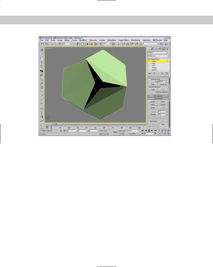
398 Part III Modeling
Figure 14-3: You can use the Break button to give each face its own vertex.
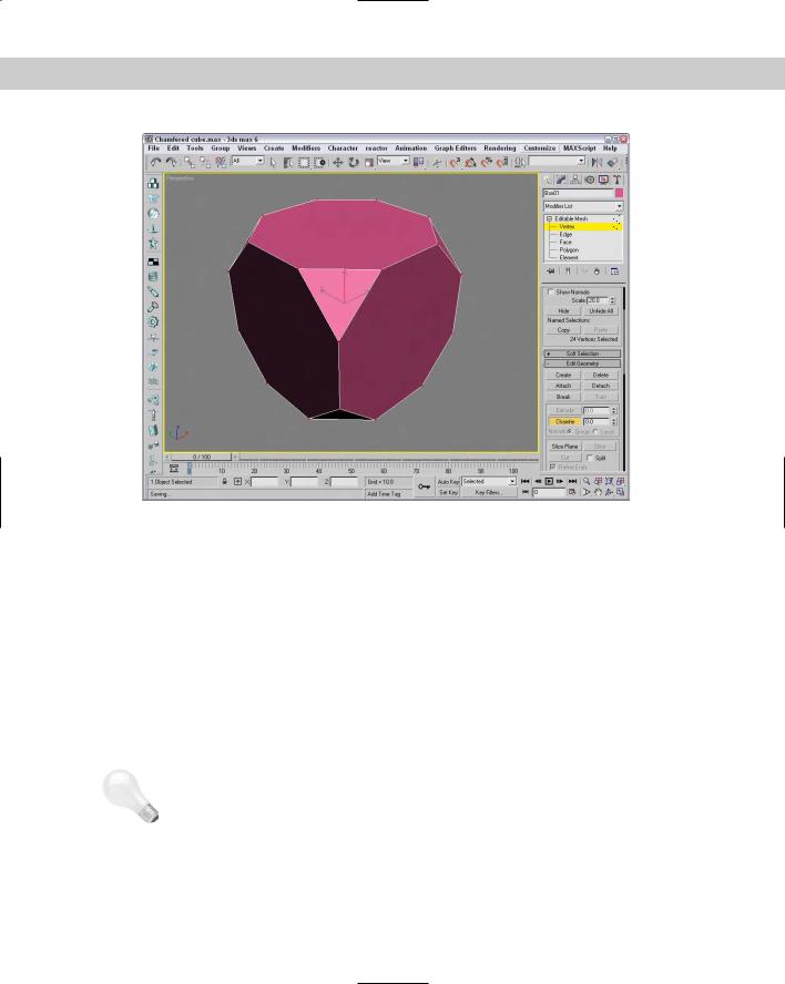
Chamfer
The Chamfer button, which is enabled in Vertex, Edge, and Border subobject modes, lets you cut the edge off a corner and replace it with a face. This existing corner vertex is deleted and automatically replaced with a face as well as vertices for each edge that was connected to the original corner vertex. The Chamfer amount is the distance the new face vertices move along the edge away from the original vertex position.
To use this feature, click the Chamfer button, and then click and drag the vertex to be chamfered, or select a vertex and enter a value in the Chamfer spinner. If multiple vertices are selected, they all are chamfered equal amounts. If you click and drag on an unselected vertex, then the current selection is dropped and the new selection is chamfered.
Figure 14-4 shows the results of chamfering all the vertices of a cube at the same time.
Slice
The Slice Plane button lets you split the mesh object along a plane. When you click the Slice Plane button, a yellow slice plane gizmo appears on the selected object. You can move, rotate, and scale this gizmo using the transform buttons. After you properly position the plane and set all options, click the Slice button to finish slicing the mesh. All intersected faces split in two. and new vertices and edges are added to the mesh where the Slice Plane intersects the original mesh.
Chapter 14 Working with Meshes and Polys 399
Figure 14-4: You use the Chamfer button to replace all vertices with faces.
The Slice Plane mode stays active until you deselect the Slice Plane button or until you rightclick in the viewport; this feature enables you to make several slices in one session. The Slice Plane button is enabled for all subobject modes. For the Editable Poly object, a Reset Plane button is located next to the Slice Plane button. Use this button to reset the slice plane to its original location.
You use the Split option to double the number of vertices along the Slice Plane. Choosing the Refine Ends option causes open ends on adjacent faces to be connected to avoid discontinuities in the surface.
Weld Selected and Weld Target
The Weld Selected button works like the Weld function for splines. To use this feature, select two or more vertices and click the Weld button. If the vertices are within the threshold value specified by the spinner to the right of the button, they are welded into one vertex. If no vertices are within the threshold, an alert box opens and notifies you of this situation.
Tip |
If you run into trouble with the Weld button and its Threshold value, try using the Collapse |
|
button. |
400 Part III Modeling
The Weld Target button lets you select a vertex and drag and drop it on top of another vertex. If the target vertex is within the number of pixels specified by the Target value, the vertices are welded into one vertex. To exit Weld Target mode, click the Target button again or rightclick in the viewport.
Both of these buttons are available only in Vertex subobject mode.
Remove Isolated Vertices and Make Planar
The Remove Isolated Vertices button deletes all isolated vertices. Vertices become isolated by some operations and add extra data to your file that is unneeded. You can search and delete them quickly with this button. Good examples of isolated vertices are those that are created using the Create button but never attached to an edge.
A single vertex or two vertices don’t define a plane, but three or more vertices do. If three or more vertices are selected, you can use the Make Planar button to make these vertices coplanar (which means that all vertices are on the same plane). Doing so positions the selected vertices so that they lie in the same plane. This is helpful if you want to build a new polygon face. Polygonal faces need to be coplanar. This button works in all subobject modes.
Collapse
The Collapse button is used to collapse all the selected subobjects to a single subobject located at the averaged center of the selection. This button is similar to the Weld button, except that the selected vertices don’t need to be within a Threshold value to be combined. This button works in all subobject modes.
Vertex Surface properties
The Surface Properties rollout in Vertex subobject mode lets you define the Weight, Color, and Illumination of object vertices. In Vertex mode, this rollout lets you give selected vertices a Weight. Vertices with higher weight have a greater pull, like the gravity of a larger planet. Several modifiers (such as MeshSmooth) use this Weight setting.
Also within this rollout are several color swatches, which enable you to select Color and Illumination colors for the selected vertices. The Alpha value sets the amount of transparency for the vertices. After you assign colors, you can then recall vertices with the same color by selecting a color (or illumination color) in the Select Vertices By section and clicking the Select button. The RGB values match all colors within the Range defined by these values.
Cross- |
You can find more information on vertex colors in Chapter 50, “Max and Games.” |
Reference |
|
Tutorial: Modeling a clown head
Now that all the editable mesh features have been covered, let’s use them to actually get some work done. In this example, you’ll quickly deform a mesh sphere to create a clown face by selecting, moving, and working with some vertices.
To create a clown head by moving vertices, follow these steps:
1.Select Create Standard Primitives Sphere, and drag in the Front viewport to create a sphere object. Then right click the sphere, and select Convert To Editable Mesh in the pop-up quadmenu.
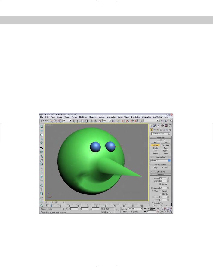
Chapter 14 Working with Meshes and Polys 401
2.Open the Modify panel. Now make a long, pointy nose by pulling a vertex outward from the sphere object. Click the small plus sign to the left of the Editable Mesh object in the Modifier Stack, and select Vertex in the hierarchy (or press the 1 key). This activates the Vertex subobject mode. Enable the Ignore Backfacing option in the Selection rollout, and select the single vertex in the center of the Front viewport. Make sure that the Select and Move button (W) is selected, and in the Left viewport, drag the vertex along the Z axis until it projects from the sphere.
3.Next, create the mouth by selecting and indenting a row of vertices in the Front viewport underneath the protruding nose. Holding down the Ctrl key will make it easy to select multiple vertices. Underneath the nose, select several vertices in a circular arc that make a smile. Then move the selected vertices along the negative Z-axis in the Left viewport.
4.For the eyes, select Create Standard Primitives Sphere and enable the AutoGrid option. Then drag in the Front viewport to create two eyes above the nose.
This clown head is just a simple example of what is possible by editing subobjects. Figure 14-5 shows the clown head in a shaded view.
Figure 14-5: A clown head created from an editable mesh by selecting and moving vertices
402 Part III Modeling
Editing edges
Edges are the lines that run between two vertices. Edges can be closed, which means that each side of the edge is connected to a face; or open, which means that only one face connects to the edge. When a hole exists in a mesh, then all edges that are adjacent to the hole are open edges. Mesh edges, such as in the interior of a shape that has been converted to a mesh, can also be invisible. These invisible edges appear as dotted lines that run across the face of the polygon.
You can select multiple edges by holding down either the Ctrl key while clicking the edges or the Alt key to remove selected edges from the selection set. You can also copy edges using the Shift key while transforming the edge. The cloned edge maintains connections to its vertices by creating new edges.
Many of the Edge subobject options work in the same way as the Vertex subobject options.
Divide
The Divide button adds a new vertex at the middle of the edge and splits the edge into two equal sections. When in Edge, Face, Border, Polygon, or Element subobject mode, the Divide button replaces the Break button. To exit Divide mode, click the Divide button again or rightclick in the viewport.
This button works in all subobject modes except Vertex.
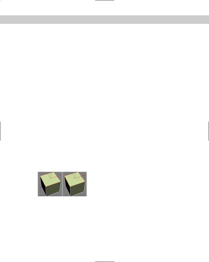
Turn
The Turn button rotates the hidden edges that break up the polygon into triangles (all polygonal faces include these hidden edges). For example, if a quadrilateral (four-sided) face has a hidden edge that runs between vertices 1 and 3, then the Turn button changes this hidden edge to run between 2 and 4. This affects how the surface is smoothed when the polygon is not coplanar.
This button is available only in Edge subobject mode for the Editable Mesh object. Figure 14-6 shows the top face of a Box object with a hidden edge cross it diagonally. The Turn button was used to turn this hidden edge.
Figure 14-6: The Turn feature is used to change the direction of edges.
Extrude
The Extrude button copies and moves the selected subobject perpendicular a given distance and connects the new copy with the original one. For example, a four edges forming a square extruded would form a box with no lid. To use this feature, select an edge or edges, click the Extrude button, and then drag in a viewport. The edges interactively show the extrude depth. Release the button when you’ve reached the desired distance.

Chapter 14 Working with Meshes and Polys 403
Alternatively, you can set an extrude depth in the Extrusion spinner. The Normal Group option extrudes all selected edges along the normal for the group (the normal runs perpendicular to the face) and the Normal Local option moves each individual edge along its local normal. To exit Extrude mode, click the Extrude button again or right-click in the viewport.
The Extrude button is enabled for Face, Polygon, and Element subobject modes for the Editable Mesh object. Figure 14-7 shows a GeoSphere object with all edges selected and extruded. The Group Normal option averages all the normals and extrudes the edges in the averaged direction. The Local Normal option extrudes each edge along its own normal.
Figure 14-7: Subobjects can be extruded along an averaged normal or locally.
Cut
The Cut button enables you to split an edge into two by cutting an existing edge. To use this feature, click the Cut button and then click on an edge where you want to start the cut. A dotted line extends from this location as you move across the surface. When the cursor is over another edge, it changes to crosshairs. Clicking on another edge creates a new edge from the first location to the new location, and all vertices are added at every edge that is crossed. You can also create a single vertex at any point along an edge by double-clicking.
The Split option creates two vertices at every junction, enabling these faces to be easily separated. The Refine Edges option maintains the continuous surface of the mesh by adding additional vertices to all adjacent faces to the cut. The Cut button is available for Editable Mesh objects in all subobject modes except Vertex.
Select Open Edges and Create Shape from Edges options
The Select Open Edges button locates and selects all open edges. Using this button is a good way to find any holes in the geometry. This feature is another one that helps eliminate potential problems with a mesh object.
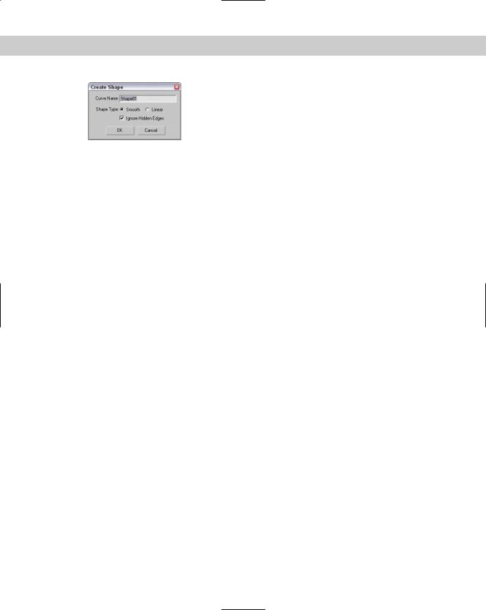
The Create Shape from Edges button creates a new spline shape from selected edges. The Create Shape dialog box appears, shown in Figure 14-8, enabling you to give the new shape a name. You can also select options for Smooth or Linear shape types and to Ignore Hidden Edges.
404 Part III Modeling
Figure 14-8: The Create Shape dialog box lets you name shapes created from selected edge subobjects.
Edge Surface properties
The Surface Properties rollout for the Editable Mesh object in the Edge subobject mode includes Visible and Invisible buttons that you can use to make edges invisible. Invisible edges are visible only in Edge subobject mode. The Auto Edge button automatically makes all selected edges less than the Threshold value invisible if the Set and Clear Edge Vis option is selected. The Set option only makes invisible edges visible, and the Clear option only makes visible edges invisible.
Editing Face, Border, Polygon, and Element subobjects
Editable Mesh objects include two different types of faces: Face and Polygon subobjects. Face subobjects have only three edges. This polygon is the simplest possible, and all other polygons can be broken down into this type of face. Polygon subobjects are any faces with more than three vertices. A Polygon subobject includes two or more faces. A dashed line contained within the polygon divides these faces.
Editable Poly objects do not need the Face subobject because they support polygon faces. Instead, they have a Border subobject. The Border subobject is polygons without any face and edges on all sides that are actually holes within the geometry.
Transforming a face or polygon object works the same way in subobject mode as in normal transformations. The Edit Geometry rollout includes many of the same buttons previously covered in the “Editing vertices” and “Editing edges” sections, but includes some additional features that apply only to Face, Border, and Polygon subobjects.
A mesh object can also contain several elements. The Element subobject mode includes all the same commands as the Face, Border, and Polygon subobject modes.
Create
You can use the Create button to create new faces and/or polygons based on new or existing vertices. To create a new face, click the Create button, which highlights all vertices in the selected mesh. Next, click a vertex to start the face; after clicking two more vertices, a new face is created. You can also create a new vertex not based on any existing vertices by holding down the Shift key while clicking.
Polygons aren’t limited to three vertices. You can click as many times as you want to add additional vertices to the polygon. Click the first vertex, or double-click to complete the polygon.
Bevel
The Bevel button appears in place of the Chamfer button for Face, Polygon, and Element subobject modes. It extrudes the Face or Polygon subobject selection and then lets you bevel the edges. To use this feature, select a face or polygon, click the Bevel button, drag up or down in
Chapter 14 Working with Meshes and Polys 405
a viewport to the Extrusion depth, and release the button. Drag again to specify the Bevel amount. The Bevel amount determines the relative size of the extruded face.
The Normal Group option extrudes all selected faces or polygons along the normal for the group, and the Normal Local option moves each individual face or polygon along its local normal. For Editable Poly objects, you can also use the bevel by polygon option. To exit Bevel mode, click the Bevel button again or right-click in the viewport. The Bevel button is enabled for all subobject modes except Vertex, Edge, and Border.
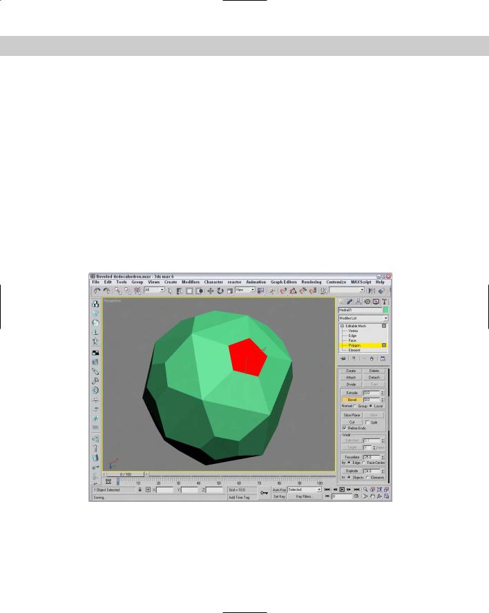
Figure 14-9 displays a poly dodecahedron. Each face has been locally extruded with a value of 20 and then locally beveled with a value of –10.
Tessellate
You can use the Tessellate button to increase the resolution of a mesh by splitting a face or polygon into several faces or polygons. You have two options to do this: Edge and Face-Center.
The Edge method splits each edge at its midpoint. For example, a triangular face would be split into three smaller triangles. The Tension spinner to the right of the Tessellate button specifies a value that is used to make the tessellated face concave or convex.
Figure 14-9: The top faces of this dodecahedron have been individually extruded and beveled.
406 Part III Modeling
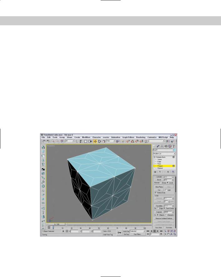
The Face-Center option creates a vertex in the center of the face and also creates three new edges, which extend from the center vertex to each original vertex. For a square polygon, this option would create six new triangular faces. (Remember, a square polygon is actually composed of two triangular faces.)
Figure 14-10 shows the faces of a cube that has been tessellated once using the Edge option and then again using the Face-Center option.
Face, Polygon, and Element Surface properties
For Face, Polygon, and Element subobjects, the Surface Properties rollout includes Flip, Unify, and Flip Normal Mode buttons to control the direction of the normal vectors. Flip reverses the direction of the normals of each selected face; Unify makes all normals face in the same direction based on the majority. The Flip Normal Mode button activates a mode where you can click individual faces and flip their normals. These buttons are available only for the Editable Mesh object.
The Surface Properties rollout also includes Material IDs and Smoothing Groups options. The Material IDs option settings are used by the Multi/Sub-Object material type to apply different materials to faces or polygons within an object. By selecting a polygon subobject, you can use these option settings to apply a unique material to the selected polygon. The Select ID button selects all subobjects that have the designated Material ID, or you can select subobjects using a material name in the drop-down list under the Select ID button.
Figure 14-10: A cube tessellated twice, using each option once
Chapter 14 Working with Meshes and Polys 407
Cross- |
You can find more information on the Multi/Sub-Object material type in Chapter 20, |
Reference |
“Creating and Applying Simple Materials.” |
|
You use the Smoothing Group option to assign a subobject to a unique smoothing group. To do this, select a subobject and click a Smoothing Group number. The Select By SG button, like the Select By ID button, opens a dialog box where you can enter a smoothing group number, and all subobjects with that number are selected. The Clear All button clears all smoothing group number assignments, and the Auto Smooth button automatically assigns smoothing group numbers based on the angle between faces as set by the value to the right of the Auto Smooth button.
Tutorial: Cleaning up imported meshes
Almost all 3D formats are mesh formats, and importing mesh objects can sometimes create problems. By collapsing an imported model to an editable mesh, you can take advantage of several of the editable mesh features to clean up these problems.
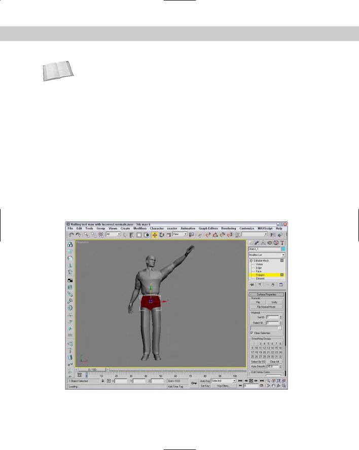
Figure 14-11 shows a model that was exported from Poser using the 3ds format. Notice that the model’s waist is black. It only appears this way because I’ve turned off the Backface Cull option in the Viewport Configuration dialog box. If it were turned on, his waist would be invisible. The problem here is that the normals for this object are pointing the wrong direction. This problem is common for imported meshes, and we fix it in this tutorial.
Figure 14-11: This mesh suffers from objects with flipped normals, which makes them invisible.