

- •Preface
- •About This Book
- •Acknowledgments
- •Contents at a Glance
- •Contents
- •Relaxing at the Beach
- •Dressing the Scene
- •Animating Motion
- •Rendering the Final Animation
- •Summary
- •The Interface Elements
- •Using the Menus
- •Using the Toolbars
- •Using the Viewports
- •Using the Command Panel
- •Using the Lower Interface Bar Controls
- •Interacting with the Interface
- •Getting Help
- •Summary
- •Understanding 3D Space
- •Using the Viewport Navigation Controls
- •Configuring the Viewports
- •Working with Viewport Backgrounds
- •Summary
- •Working with Max Scene Files
- •Setting File Preferences
- •Importing and Exporting
- •Referencing External Objects
- •Using the File Utilities
- •Accessing File Information
- •Summary
- •Customizing Modify and Utility Panel Buttons
- •Working with Custom Interfaces
- •Configuring Paths
- •Selecting System Units
- •Setting Preferences
- •Summary
- •Creating Primitive Objects
- •Exploring the Primitive Object Types
- •Summary
- •Selecting Objects
- •Setting Object Properties
- •Hiding and Freezing Objects
- •Using Layers
- •Summary
- •Cloning Objects
- •Understanding Cloning Options
- •Mirroring Objects
- •Cloning over Time
- •Spacing Cloned Objects
- •Creating Arrays of Objects
- •Summary
- •Working with Groups
- •Building Assemblies
- •Building Links between Objects
- •Displaying Links and Hierarchies
- •Working with Linked Objects
- •Summary
- •Using the Schematic View Window
- •Working with Hierarchies
- •Setting Schematic View Preferences
- •Using List Views
- •Summary
- •Working with the Transformation Tools
- •Using Pivot Points
- •Using the Align Commands
- •Using Grids
- •Using Snap Options
- •Summary
- •Exploring the Modifier Stack
- •Exploring Modifier Types
- •Summary
- •Exploring the Modeling Types
- •Working with Subobjects
- •Modeling Helpers
- •Summary
- •Drawing in 2D
- •Editing Splines
- •Using Spline Modifiers
- •Summary
- •Creating Editable Mesh and Poly Objects
- •Editing Mesh Objects
- •Editing Poly Objects
- •Using Mesh Editing Modifiers
- •Summary
- •Introducing Patch Grids
- •Editing Patches
- •Using Modifiers on Patch Objects
- •Summary
- •Creating NURBS Curves and Surfaces
- •Editing NURBS
- •Working with NURBS
- •Summary
- •Morphing Objects
- •Creating Conform Objects
- •Creating a ShapeMerge Object
- •Creating a Terrain Object
- •Using the Mesher Object
- •Working with BlobMesh Objects
- •Creating a Scatter Object
- •Creating Connect Objects
- •Modeling with Boolean Objects
- •Creating a Loft Object
- •Summary
- •Understanding the Various Particle Systems
- •Creating a Particle System
- •Using the Spray and Snow Particle Systems
- •Using the Super Spray Particle System
- •Using the Blizzard Particle System
- •Using the PArray Particle System
- •Using the PCloud Particle System
- •Using Particle System Maps
- •Controlling Particles with Particle Flow
- •Summary
- •Understanding Material Properties
- •Working with the Material Editor
- •Using the Material/Map Browser
- •Using the Material/Map Navigator
- •Summary
- •Using the Standard Material
- •Using Shading Types
- •Accessing Other Parameters
- •Using External Tools
- •Summary
- •Using Compound Materials
- •Using Raytrace Materials
- •Using the Matte/Shadow Material
- •Using the DirectX 9 Shader
- •Applying Multiple Materials
- •Material Modifiers
- •Summary
- •Understanding Maps
- •Understanding Material Map Types
- •Using the Maps Rollout
- •Using the Map Path Utility
- •Using Map Instances
- •Summary
- •Mapping Modifiers
- •Using the Unwrap UVW modifier
- •Summary
- •Working with Cameras
- •Setting Camera Parameters
- •Summary
- •Using the Camera Tracker Utility
- •Summary
- •Using Multi-Pass Cameras
- •Creating Multi-Pass Camera Effects
- •Summary
- •Understanding the Basics of Lighting
- •Getting to Know the Light Types
- •Creating and Positioning Light Objects
- •Viewing a Scene from a Light
- •Altering Light Parameters
- •Working with Photometric Lights
- •Using the Sunlight and Daylight Systems
- •Using Volume Lights
- •Summary
- •Selecting Advanced Lighting
- •Using Local Advanced Lighting Settings
- •Tutorial: Excluding objects from light tracing
- •Summary
- •Understanding Radiosity
- •Using Local and Global Advanced Lighting Settings
- •Working with Advanced Lighting Materials
- •Using Lighting Analysis
- •Summary
- •Using the Time Controls
- •Working with Keys
- •Using the Track Bar
- •Viewing and Editing Key Values
- •Using the Motion Panel
- •Using Ghosting
- •Animating Objects
- •Working with Previews
- •Wiring Parameters
- •Animation Modifiers
- •Summary
- •Understanding Controller Types
- •Assigning Controllers
- •Setting Default Controllers
- •Examining the Various Controllers
- •Summary
- •Working with Expressions in Spinners
- •Understanding the Expression Controller Interface
- •Understanding Expression Elements
- •Using Expression Controllers
- •Summary
- •Learning the Track View Interface
- •Working with Keys
- •Editing Time
- •Editing Curves
- •Filtering Tracks
- •Working with Controllers
- •Synchronizing to a Sound Track
- •Summary
- •Understanding Your Character
- •Building Bodies
- •Summary
- •Building a Bones System
- •Using the Bone Tools
- •Using the Skin Modifier
- •Summary
- •Creating Characters
- •Working with Characters
- •Using Character Animation Techniques
- •Summary
- •Forward versus Inverse Kinematics
- •Creating an Inverse Kinematics System
- •Using the Various Inverse Kinematics Methods
- •Summary
- •Creating and Binding Space Warps
- •Understanding Space Warp Types
- •Combining Particle Systems with Space Warps
- •Summary
- •Understanding Dynamics
- •Using Dynamic Objects
- •Defining Dynamic Material Properties
- •Using Dynamic Space Warps
- •Using the Dynamics Utility
- •Using the Flex Modifier
- •Summary
- •Using reactor
- •Using reactor Collections
- •Creating reactor Objects
- •Calculating and Previewing a Simulation
- •Constraining Objects
- •reactor Troubleshooting
- •Summary
- •Understanding the Max Renderers
- •Previewing with ActiveShade
- •Render Parameters
- •Rendering Preferences
- •Creating VUE Files
- •Using the Rendered Frame Window
- •Using the RAM Player
- •Reviewing the Render Types
- •Using Command-Line Rendering
- •Creating Panoramic Images
- •Getting Printer Help
- •Creating an Environment
- •Summary
- •Creating Atmospheric Effects
- •Using the Fire Effect
- •Using the Fog Effect
- •Summary
- •Using Render Elements
- •Adding Render Effects
- •Creating Lens Effects
- •Using Other Render Effects
- •Summary
- •Using Raytrace Materials
- •Using a Raytrace Map
- •Enabling mental ray
- •Summary
- •Understanding Network Rendering
- •Network Requirements
- •Setting up a Network Rendering System
- •Starting the Network Rendering System
- •Configuring the Network Manager and Servers
- •Logging Errors
- •Using the Monitor
- •Setting up Batch Rendering
- •Summary
- •Compositing with Photoshop
- •Video Editing with Premiere
- •Video Compositing with After Effects
- •Introducing Combustion
- •Using Other Compositing Solutions
- •Summary
- •Completing Post-Production with the Video Post Interface
- •Working with Sequences
- •Adding and Editing Events
- •Working with Ranges
- •Working with Lens Effects Filters
- •Summary
- •What Is MAXScript?
- •MAXScript Tools
- •Setting MAXScript Preferences
- •Types of Scripts
- •Writing Your Own MAXScripts
- •Learning the Visual MAXScript Editor Interface
- •Laying Out a Rollout
- •Summary
- •Working with Plug-Ins
- •Locating Plug-Ins
- •Summary
- •Low-Res Modeling
- •Using Channels
- •Using Vertex Colors
- •Rendering to a Texture
- •Summary
- •Max and Architecture
- •Using AEC Objects
- •Using Architectural materials
- •Summary
- •Tutorial: Creating Icy Geometry with BlobMesh
- •Tutorial: Using Caustic Photons to Create a Disco Ball
- •Summary
- •mental ray Rendering System
- •Particle Flow
- •reactor 2.0
- •Schematic View
- •BlobMesh
- •Spline and Patch Features
- •Import and Export
- •Shell Modifier
- •Vertex Paint and Channel Info
- •Architectural Primitives and Materials
- •Minor Improvements
- •Choosing an Operating System
- •Hardware Requirements
- •Installing 3ds max 6
- •Authorizing the Software
- •Setting the Display Driver
- •Updating Max
- •Moving Max to Another Computer
- •Using Keyboard Shortcuts
- •Using the Hotkey Map
- •Main Interface Shortcuts
- •Dialog Box Shortcuts
- •Miscellaneous Shortcuts
- •System Requirements
- •Using the CDs with Windows
- •What’s on the CDs
- •Troubleshooting
- •Index
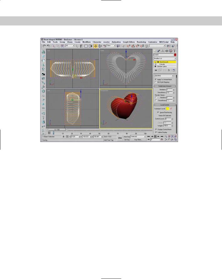
Chapter 14 Working with Meshes and Polys 429
Figure 14-28: A NURMS heart created with the MeshSmooth modifier
HSDS modifier
You use the HSDS (Hierarchical SubDivision Surfaces) modifier to increase the resolution and smoothing of a localized area. It works like the Tessellate modifier except that it can work with small subobject sections instead of the entire object surface. The HSDS modifier lets you work with Vertex, Edge, Polygon, and Element subobjects. After a subobject area is selected, you can click the Subdivide button to subdivide the area.
The Level of Detail spinner lets you move back and forth between the various subdivision hierarchy levels. When polygon subobjects are selected, you can also Delete or Hide them. The Adaptive Subdivision button opens the Adaptive Subdivision dialog box in which you can specify the detail parameters. This modifier also includes a Soft Selection rollout and an Edge rollout where you can specify a Crease value to maintain sharp edges.
Summary
Meshes are probably the most common 3D modeling types. You can create them by converting objects to Editable Meshes or Editable Poly objects or by collapsing the Stack. Editable Meshes and Editable Poly objects in Max have a host of features for editing meshes, as you learned in this chapter.
430 Part III Modeling
More specifically, in this chapter you
Created Editable Mesh and Editable Poly objects by converting other objects or applying the Edit Mesh modifier
Discovered the features of the Editable Mesh and Editable Poly objects
Learned to select and use the various mesh subobject modes
Discovered the various modifiers that you can use with mesh objects
In the next chapter, you learn about modeling and working with patch objects.
|
|
|

Creating and
Editing Patches
Patches are a modeling type that exists somewhere between polygon meshes and NURBS. They are essentially polygon surfaces
stretched along a closed spline. Modifying the spline alters the surface of the patch.
In many ways, patches have advantages over the more common mesh objects. They take less memory to store, are easier to edit at the edges, and are easy to join to one another.
Introducing Patch Grids
Because patches have splines along their edges, a patch can be deformed in ways that a normal polygon cannot. For example, a polygon always needs to be coplanar, meaning that if you look at it on edge, it appears as a line. A patch doesn’t have this requirement and can actually bend, which permits greater control over the surface and makes it better for modeling things like clothes and natural objects like leaves.
Another key advantage of Patch objects is that they efficiently represent the object geometry. If you examine a mesh object, you’ll notice that they contain a discrete vertex at the intersection of every edge at the corner of every face. Patch grids, on the other hand, have a vertex only at the corner of every patch. Each patch can consist of several faces. This reduction of vertices makes patches much cleaner and less cumbersome objects to work with.
Creating a patch grid
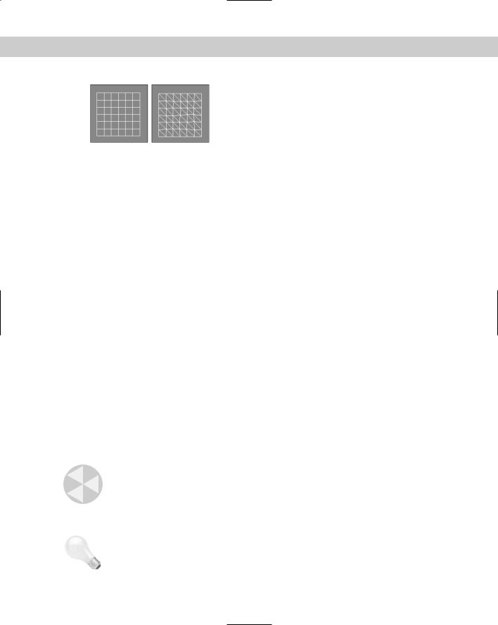
Patches are named according to the number of vertices at their edges; for example, a Tri Patch has three vertices, a Quad Patch has four vertices, and so on. The default Quad Patch is made up of 36 visible rectangular faces, and the default Tri Patch has 72 triangular faces, as shown in Figure 15-1.
15C H A P T E R
In This Chapter
Creating patch grids
Editing patches
Working with patch subobjects
432 Part III Modeling
Figure 15-1: A Quad Patch and a Tri Patch
To create patches, select the Create Patch Grids Quad Patch or Tri Patch menu commands. This opens the Create panel. Select the Geometry category, and then select Patch Grids in the drop-down list. To create a patch grid, click in a viewport, and drag to specify the dimensions of the grid.
You can also use the Keyboard Entry rollout to create patch grids with precise dimensions. To use this rollout, enter the grid’s position coordinates and its dimensions and click the Create button. The X, Y, and Z coordinates define the location of the center of the grid.
The Patch Grid Parameters rollout includes Length and Width values and values for the number of Segments for each dimension (but only for the Quad Patch). A Segment value of 1 creates six rows or columns of segments, so the total number of polygons for a Quad Patch never drops below 36. Tri Patches do not have a Segments parameter. You can also select to automatically Generate Mapping Coordinates.
Newly created patches are always flat.
Tutorial: Creating a checkerboard
In this tutorial, we create a simple checkerboard. To keep the white squares separate from the black squares, we use Quad and Tri Patches.
To create a checkerboard from patch surfaces, follow these steps:
1.Right-click the Snap button on the main toolbar; in the Grid and Snap Settings dialog box that appears, make sure that the Grid Points option is enabled. Then enable the Snap button on the main toolbar (keyboard shortcut, S).
2.Select Create Patch Grids Quad Patch and, in the Top view, create a perfect square using the grid points. Click the color swatch in the Name and Color rollout, and select the color black.
3.In the Command Panel, click the Tri Patch button and drag in the Top view to create an equally sized patch to the right of the first object. Select the Tri Patch, click its color swatch, and change its object color to white.
Caution |
With the Tri Patch’s object color set to white, telling when it is selected can be difficult. |
4.Repeat Steps 2 and 3, alternating which color comes first until the entire 8×8 checkerboard is complete.
Tip |
An easier way to accomplish the checkerboard would be to create the first two squares and |
|
then to use the Array dialog box to create the rest. Find out more about the Array dialog box |
|
in Chapter 7, “Cloning Objects and Creating Object Arrays.” |
Figure 15-2 shows the completed checkerboard.