


234 Part II Working with Objects
Summary
Many ways to clone an object are available. You can use the Clone command under the Edit menu or the Shift-clone feature for quickly creating numerous clones. Clones can be copies, instances, or references. Each differs in how it retains links to the original object. You can also clone using the Mirror, Snapshot, and Spacing tools.
Arrays are another means of cloning. You can use the Array dialog box to produce clones in three different dimensions, and you can specify the offset transformations.
This chapter covered the following cloning topics:
Cloning objects and Shift-cloning
Understanding copies, instances, and references
Using the Mirror, Snapshot, and Spacing tools
Building linear, circular, and spiral arrays of objects
Using the Ring Array system
In the next chapter, you learn to group objects and link them into hierarchies. Then you’ll be able to organize all the objects that you’ve learned to create.
|
|
|

Grouping and
Linking Objects
Now that you’ve learned how to select and clone objects, you’ll want to learn how to group objects together in an easily acces-
sible form, especially as a scene becomes more complex. Max’s grouping features enable you to organize all the objects that you’re dealing with, thereby making your workflow more efficient.
Another way of organizing objects is to build a linked hierarchy. A linked hierarchy attaches, or links, one object to another and makes it possible to transform the attached object by moving the one to which it is linked. For example, the arm is a classic example of a linked hierarchy — when the shoulder rotates, so do the elbow, wrist, and fingers. Establishing linked hierarchies can make moving, positioning, and animating many objects easy.
Working with Groups
Grouping objects organizes them and makes them easier to select and transform. Groups are different from selection sets in that groups exist like one object. Selecting any object in the group selects the entire group, whereas selecting an object in a selection set selects only that object and not the selection set. You can open groups to add, delete, or reposition objects within the group. Groups can also contain other groups. This is called nesting groups.
|
Creating groups |
|
The Group command enables you to create a group. To do so, simply |
|
select the desired objects and choose Group Group. A simple Name |
|
Group dialog box opens and enables you to give the group a name. |
|
The newly created group displays a new bounding box that encom- |
|
passes all the objects in the group. |
Tip |
You can always identify groups in the Select by Name dialog box |
|
because they are surrounded by square brackets, and groups |
|
appear in bold in the Name and Color rollout of the Command |
|
Panel. |
|
Ungrouping objects |
C 8H A P T E R
In This Chapter
Grouping objects
Building assemblies
Understanding root, parent, and child relationships
Linking and unlinking objects
The Ungroup command enables you to break up a group (kind of like a poor music album). To do so, simply select the desired group and

236 Part II Working with Objects
choose Group Ungroup. This menu command dissolves the group, and all the objects within the group revert to separate objects. The Ungroup command breaks up only the currently selected group. All nested groups within a group stay intact.
The easiest way to dissolve an entire group, including any nested groups, is with the Explode command. This command eliminates the group and the groups within the group and makes each object separate.
Opening and closing groups
The Open command enables you to access the objects within a group. Grouped objects move, scale, and rotate as a unit when transformed, but individual objects within a group can be transformed independently after you open a group with the Open command.
To move an individual object in a group, select the group and choose Group Open. The white bounding box changes to pink. Then select an object within the group, and move it with the Select and Move button (keyboard shortcut, W). Choose Group Close to reinstate the group.
Attaching and detaching objects
The Attach and Detach commands enable you to insert or remove objects from an opened group without dissolving the group. To attach objects to an existing group, select an object, select the Attach menu command, and then click on the group to which you want to add the object. To detach an object from a group, you need to open the group and select the Detach menu command. Remember to close the group when finished.
Tutorial: Grouping a plane’s parts together
Positioning objects relative to one another takes careful and precise work. After spending the time to place the wings, tail, and prop on a plane exactly where they need to be, transforming these objects can spell disaster. By grouping all the objects together, you can move all the objects at once.
For this tutorial, you can get some practice grouping all the parts of an airplane together. Follow these steps:
1.Open the T-28 Trojan plane.max file from the Chap 08 directory on the CD-ROM. This file includes a model created by Viewpoint Datalabs.
2.Click the Select by Name button on the main toolbar (or press the H key) to open the Select by Name dialog box. In this dialog box, notice all the different plane parts. Click the All button to select all the separate objects, and click the Select button to close the dialog box.
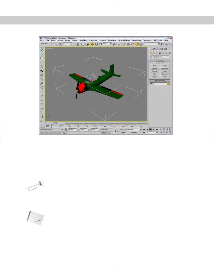
3.With all the objects selected, choose Group Group to open the Group dialog box. Give the group the name Plane, and click OK.
4.Click the Select and Move button (or press W), and click and drag the plane. The entire group now moves together.
Figure 8-1 shows the plane grouped as one unit. Notice how only one set of brackets surrounds the deer in the Perspective viewport. The group name is displayed in the Name field of the Command Panel instead of saying Multiple Selected.
Chapter 8 Grouping and Linking Objects 237
Figure 8-1: The plane moves as one unit after its objects are grouped.
Building Assemblies
At the bottom of the Group menu is a menu item called Assembly with a submenu that looks frightfully similar to the Group menu. The difference between a group and an assembly is that an assembly can include a light object and it has a Luminaire helper object as its head. This enables you build light fixtures where the light is actually grouped (or assembled) with the light stand objects. Once built, you can control the light by selecting and moving the light assembly.
New |
The Assembly menu is new to 3ds max 6. |
Feature |
|
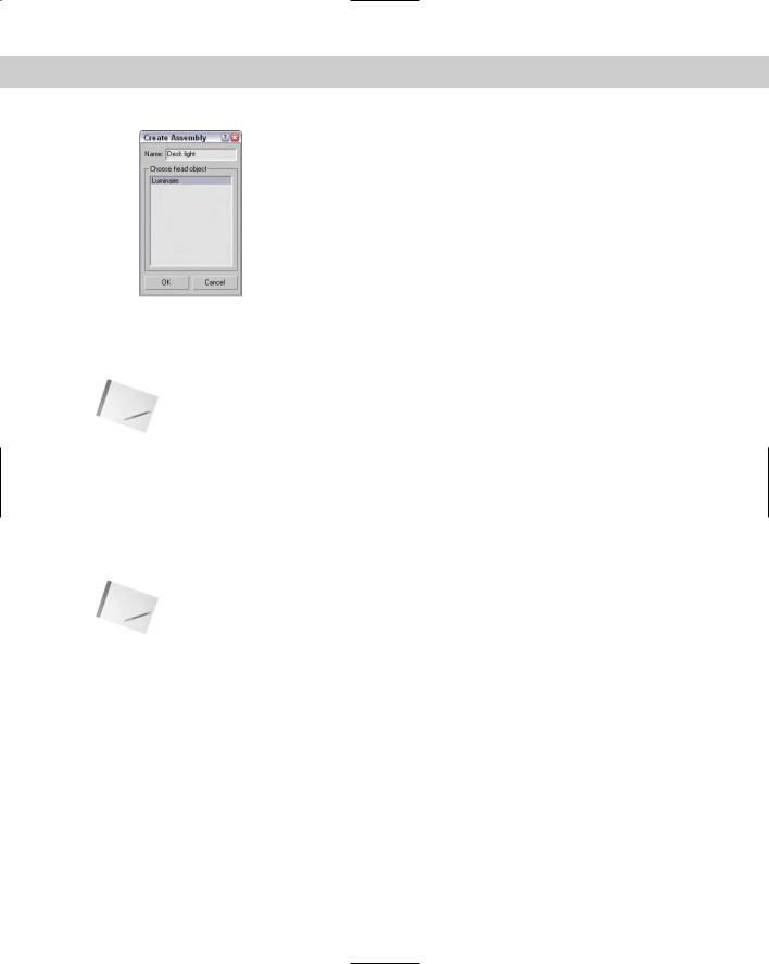
After you’ve create the geometry for a light assembly, you can create an assembly with the Group Assembly Assemble menu command. This opens the Create Assembly dialog box, shown in Figure 8-2, where you can name the assembly and add a Luminaire object as the head object.
Note |
Characters that are created with the Character Create Character command are structurally |
|
the same as assemblies. Both have head objects that control the position of all the objects |
|
that make up the structure. |
238 Part II Working with Objects
Figure 8-2: The Create Assembly dialog box lets you choose a light head object.
Because the Luminaire object is the head object, you can see its parameters in the Modify panel whenever the assembly is selected. Its parameters include a Dimmer value and a Filter Color. These parameters are used only if they are wired to an actual light object that is included in the assembly.
Note If you apply a modifier to an assembly, it affects only the Luminaire head object, so Parametric Deformation modifiers like Twist have no effect. If you open the assembly, you can select and apply a modifier to an individual assembly object.
Adding lights to assemblies
If you know that your light characteristics aren’t going to change, then set up the parameters for your light object before you build the assembly and the light object will provide constant light. If you ever need to change a light setting, just open the assembly with the Group Assembly Open menu command. Then select the light object, and its parameters appear in the Modify panel. After you’ve changed the light parameters, close the assembly again with the Group Assembly Close menu command.
Note Adding a light object to an assembly without wiring it to the Luminaire object works the same as if you grouped the objects with the Group command. The real benefit of an assembly comes from wiring the light parameters.
All other commands in the Assembly submenu work just like their counterparts in the Group menu.
Wiring Luminaire helper objects to light objects
Luminaire objects can be confusing because they don’t actually add light to an assembly. If you’re curious about the Luminaire objects, you can find them in the Assembly Heads subcategory of the Helper category.
The benefit of the Luminaire helper object is that it can add to an assembly some simple parameters that are accessible whenever the assembly is selected. These parameters work only if you wire them to the parameters of the light object included in the assembly.
Chapter 8 Grouping and Linking Objects 239
Cross- |
You can learn more about wiring parameters in Chapter 30, “Animation Basics.” |
Reference |
|
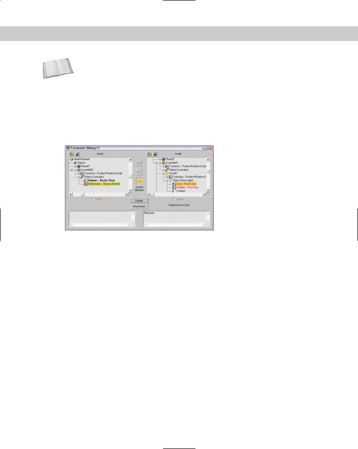
To wire the Luminaire parameters to the light object’s parameters, select the assembly and open the Parameter Wiring dialog box with the Animation Wire Parameters Parameter Wiring Dialog menu command. In the left pane, locate and select the Dimmer parameter under the Object (Luminaire) track. Locate and select the Multiplier parameter under the Object (Light) track, which is under the Assembly01 track in the right pane. Click the one-way connection button in the center of the dialog box that links the Dimmer to the Multiplier parameters, and click the Connect button. Next wire the FilterColor parameter to the light’s Color parameter. Figure 8-3 shows the Parameter Wiring dialog box for this simple assembly.
Figure 8-3: The Parameter Wiring dialog can make the light object’s parameter.
After the assembly light is wired to the Luminaire parameters, you can use the Dimmer and Filter Color parameters in the Modify panel whenever the assembly is selected.
Tutorial: Creating a flashlight assembly
One of the most portable of lights is the ubiquitous flashlight. In this tutorial, we create an assembly and wire the light parameters to the Luminaire head object’s parameters.
To create a flashlight assembly, follow these steps:
1.Open the Flashlight assembly.max file from the Chap 08 directory on the CD-ROM. This file includes a flashlight model with a single free spotlight.
2.Select all objects within the scene with the Edit Select All (Ctrl+A) menu command. Then select the Group Assembly Assemble menu command. In the Create Assembly dialog box, name the assembly Flashlight and click OK.
240 Part II Working with Objects
3.To wire the Luminaire head object’s parameters to the light object, select Animation Wire Parameters Parameter Wire Dialog. This opens the Parameter Wiring dialog box with the Object (Luminaire) track selected in the left pane. Expand the Object (Luminaire) track, and select the Dimmer parameter.
4.In the right pane of the Parameter Wiring dialog box, expand the Flashlight track, locate and expand the Fspot01 light object, and select the Multiplier track under the Object (Free Spot) track. Then click the Control Direction arrow in the center of the dialog box that points to the right, and click Connect.
5.With the Parameter Wiring dialog box still open, select the FilterColor track in the left pane and the Color track in the right pane, and connect these two parameters with the Connect button. Click on the Close button in the upper-right corner of the dialog box.
6.In the Luminaire Parameters rollout of the Command Panel, drag the Dimmer parameter down to 1.0 and watch light in the flashlight dim.
Figure 8-4 shows the resulting flashlight assembly. This light fixture can now be positioned and used in the scene.
Figure 8-4: This flashlight assembly can be controlled using the simple Luminaire parameters.