

- •Preface
- •About This Book
- •Acknowledgments
- •Contents at a Glance
- •Contents
- •Relaxing at the Beach
- •Dressing the Scene
- •Animating Motion
- •Rendering the Final Animation
- •Summary
- •The Interface Elements
- •Using the Menus
- •Using the Toolbars
- •Using the Viewports
- •Using the Command Panel
- •Using the Lower Interface Bar Controls
- •Interacting with the Interface
- •Getting Help
- •Summary
- •Understanding 3D Space
- •Using the Viewport Navigation Controls
- •Configuring the Viewports
- •Working with Viewport Backgrounds
- •Summary
- •Working with Max Scene Files
- •Setting File Preferences
- •Importing and Exporting
- •Referencing External Objects
- •Using the File Utilities
- •Accessing File Information
- •Summary
- •Customizing Modify and Utility Panel Buttons
- •Working with Custom Interfaces
- •Configuring Paths
- •Selecting System Units
- •Setting Preferences
- •Summary
- •Creating Primitive Objects
- •Exploring the Primitive Object Types
- •Summary
- •Selecting Objects
- •Setting Object Properties
- •Hiding and Freezing Objects
- •Using Layers
- •Summary
- •Cloning Objects
- •Understanding Cloning Options
- •Mirroring Objects
- •Cloning over Time
- •Spacing Cloned Objects
- •Creating Arrays of Objects
- •Summary
- •Working with Groups
- •Building Assemblies
- •Building Links between Objects
- •Displaying Links and Hierarchies
- •Working with Linked Objects
- •Summary
- •Using the Schematic View Window
- •Working with Hierarchies
- •Setting Schematic View Preferences
- •Using List Views
- •Summary
- •Working with the Transformation Tools
- •Using Pivot Points
- •Using the Align Commands
- •Using Grids
- •Using Snap Options
- •Summary
- •Exploring the Modifier Stack
- •Exploring Modifier Types
- •Summary
- •Exploring the Modeling Types
- •Working with Subobjects
- •Modeling Helpers
- •Summary
- •Drawing in 2D
- •Editing Splines
- •Using Spline Modifiers
- •Summary
- •Creating Editable Mesh and Poly Objects
- •Editing Mesh Objects
- •Editing Poly Objects
- •Using Mesh Editing Modifiers
- •Summary
- •Introducing Patch Grids
- •Editing Patches
- •Using Modifiers on Patch Objects
- •Summary
- •Creating NURBS Curves and Surfaces
- •Editing NURBS
- •Working with NURBS
- •Summary
- •Morphing Objects
- •Creating Conform Objects
- •Creating a ShapeMerge Object
- •Creating a Terrain Object
- •Using the Mesher Object
- •Working with BlobMesh Objects
- •Creating a Scatter Object
- •Creating Connect Objects
- •Modeling with Boolean Objects
- •Creating a Loft Object
- •Summary
- •Understanding the Various Particle Systems
- •Creating a Particle System
- •Using the Spray and Snow Particle Systems
- •Using the Super Spray Particle System
- •Using the Blizzard Particle System
- •Using the PArray Particle System
- •Using the PCloud Particle System
- •Using Particle System Maps
- •Controlling Particles with Particle Flow
- •Summary
- •Understanding Material Properties
- •Working with the Material Editor
- •Using the Material/Map Browser
- •Using the Material/Map Navigator
- •Summary
- •Using the Standard Material
- •Using Shading Types
- •Accessing Other Parameters
- •Using External Tools
- •Summary
- •Using Compound Materials
- •Using Raytrace Materials
- •Using the Matte/Shadow Material
- •Using the DirectX 9 Shader
- •Applying Multiple Materials
- •Material Modifiers
- •Summary
- •Understanding Maps
- •Understanding Material Map Types
- •Using the Maps Rollout
- •Using the Map Path Utility
- •Using Map Instances
- •Summary
- •Mapping Modifiers
- •Using the Unwrap UVW modifier
- •Summary
- •Working with Cameras
- •Setting Camera Parameters
- •Summary
- •Using the Camera Tracker Utility
- •Summary
- •Using Multi-Pass Cameras
- •Creating Multi-Pass Camera Effects
- •Summary
- •Understanding the Basics of Lighting
- •Getting to Know the Light Types
- •Creating and Positioning Light Objects
- •Viewing a Scene from a Light
- •Altering Light Parameters
- •Working with Photometric Lights
- •Using the Sunlight and Daylight Systems
- •Using Volume Lights
- •Summary
- •Selecting Advanced Lighting
- •Using Local Advanced Lighting Settings
- •Tutorial: Excluding objects from light tracing
- •Summary
- •Understanding Radiosity
- •Using Local and Global Advanced Lighting Settings
- •Working with Advanced Lighting Materials
- •Using Lighting Analysis
- •Summary
- •Using the Time Controls
- •Working with Keys
- •Using the Track Bar
- •Viewing and Editing Key Values
- •Using the Motion Panel
- •Using Ghosting
- •Animating Objects
- •Working with Previews
- •Wiring Parameters
- •Animation Modifiers
- •Summary
- •Understanding Controller Types
- •Assigning Controllers
- •Setting Default Controllers
- •Examining the Various Controllers
- •Summary
- •Working with Expressions in Spinners
- •Understanding the Expression Controller Interface
- •Understanding Expression Elements
- •Using Expression Controllers
- •Summary
- •Learning the Track View Interface
- •Working with Keys
- •Editing Time
- •Editing Curves
- •Filtering Tracks
- •Working with Controllers
- •Synchronizing to a Sound Track
- •Summary
- •Understanding Your Character
- •Building Bodies
- •Summary
- •Building a Bones System
- •Using the Bone Tools
- •Using the Skin Modifier
- •Summary
- •Creating Characters
- •Working with Characters
- •Using Character Animation Techniques
- •Summary
- •Forward versus Inverse Kinematics
- •Creating an Inverse Kinematics System
- •Using the Various Inverse Kinematics Methods
- •Summary
- •Creating and Binding Space Warps
- •Understanding Space Warp Types
- •Combining Particle Systems with Space Warps
- •Summary
- •Understanding Dynamics
- •Using Dynamic Objects
- •Defining Dynamic Material Properties
- •Using Dynamic Space Warps
- •Using the Dynamics Utility
- •Using the Flex Modifier
- •Summary
- •Using reactor
- •Using reactor Collections
- •Creating reactor Objects
- •Calculating and Previewing a Simulation
- •Constraining Objects
- •reactor Troubleshooting
- •Summary
- •Understanding the Max Renderers
- •Previewing with ActiveShade
- •Render Parameters
- •Rendering Preferences
- •Creating VUE Files
- •Using the Rendered Frame Window
- •Using the RAM Player
- •Reviewing the Render Types
- •Using Command-Line Rendering
- •Creating Panoramic Images
- •Getting Printer Help
- •Creating an Environment
- •Summary
- •Creating Atmospheric Effects
- •Using the Fire Effect
- •Using the Fog Effect
- •Summary
- •Using Render Elements
- •Adding Render Effects
- •Creating Lens Effects
- •Using Other Render Effects
- •Summary
- •Using Raytrace Materials
- •Using a Raytrace Map
- •Enabling mental ray
- •Summary
- •Understanding Network Rendering
- •Network Requirements
- •Setting up a Network Rendering System
- •Starting the Network Rendering System
- •Configuring the Network Manager and Servers
- •Logging Errors
- •Using the Monitor
- •Setting up Batch Rendering
- •Summary
- •Compositing with Photoshop
- •Video Editing with Premiere
- •Video Compositing with After Effects
- •Introducing Combustion
- •Using Other Compositing Solutions
- •Summary
- •Completing Post-Production with the Video Post Interface
- •Working with Sequences
- •Adding and Editing Events
- •Working with Ranges
- •Working with Lens Effects Filters
- •Summary
- •What Is MAXScript?
- •MAXScript Tools
- •Setting MAXScript Preferences
- •Types of Scripts
- •Writing Your Own MAXScripts
- •Learning the Visual MAXScript Editor Interface
- •Laying Out a Rollout
- •Summary
- •Working with Plug-Ins
- •Locating Plug-Ins
- •Summary
- •Low-Res Modeling
- •Using Channels
- •Using Vertex Colors
- •Rendering to a Texture
- •Summary
- •Max and Architecture
- •Using AEC Objects
- •Using Architectural materials
- •Summary
- •Tutorial: Creating Icy Geometry with BlobMesh
- •Tutorial: Using Caustic Photons to Create a Disco Ball
- •Summary
- •mental ray Rendering System
- •Particle Flow
- •reactor 2.0
- •Schematic View
- •BlobMesh
- •Spline and Patch Features
- •Import and Export
- •Shell Modifier
- •Vertex Paint and Channel Info
- •Architectural Primitives and Materials
- •Minor Improvements
- •Choosing an Operating System
- •Hardware Requirements
- •Installing 3ds max 6
- •Authorizing the Software
- •Setting the Display Driver
- •Updating Max
- •Moving Max to Another Computer
- •Using Keyboard Shortcuts
- •Using the Hotkey Map
- •Main Interface Shortcuts
- •Dialog Box Shortcuts
- •Miscellaneous Shortcuts
- •System Requirements
- •Using the CDs with Windows
- •What’s on the CDs
- •Troubleshooting
- •Index
Chapter 15 Creating and Editing Patches 447
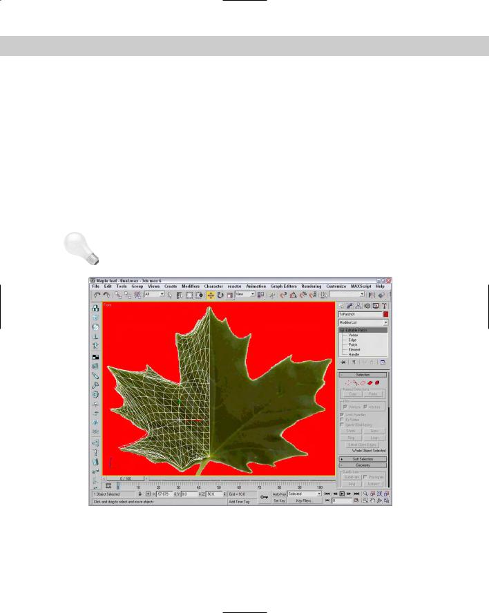
vertex that lies along the outer edge of the leaf, and move its handles so the patch edge aligns with the background leaf’s border. If the handles move together, hold down the Shift key to move them individually.
7.Deselect the Vertex subobject mode. In the Surface Properties rollout, enable all the options, and set the Relax Value to 1.0 and the Iterations to 50.
This smoothes out the wrinkles in the patch.
Figure 15-13 shows the completed maple leaf patch (half of it, anyway). To complete this leaf, use the Mirror tool and add a spline object for the stem.
Using Modifiers on Patch Objects
|
Several modifiers work specifically on patch objects. The Modifiers Patch/Spline Editing |
|
submenu contains most of these modifiers. |
Tip |
Many other modifiers work on patch objects. To see which modifiers work on patch objects, |
|
select the patch object and check the Modifiers menu to see which modifiers are enabled. |
Figure 15-13: By repositioning the vertex handles, you can make the patch object match the leaf’s edges precisely.

448 Part III Modeling
Patch Select modifier
The Patch Select modifier enables you to select patch subobjects, including Vertex, Edge, Patch, and Element. You can copy and paste named selection sets. The selection can then be passed up the Stack to the next modifier. The Patch Select modifier provides a way to apply a separate modifier to a subobject selection.
Edit Patch modifier
This modifier includes tools for editing patch objects. The features of this modifier are the same as those of the Editable Patch object. If you want to animate the features of an Editable Patch, use the Edit Patch modifier. You can even apply the Edit Patch modifier to an Editable Patch. The key benefit of the Edit Patch modifier is that it enables you to edit patch subobjects while maintaining the parametric nature of the object.
Delete Patch modifier
You can use the Delete Patch modifier to delete a patch subobject from a patch object. You use the Patch Select modifier to select the patch subobjects to delete, and you apply the Delete Patch modifier to the Patch Select modifier.
Using the Surface tools
The surface tools, which include the CrossSection and Surface modifiers, provide a way to model that is similar to lofting. The CrossSection modifier takes several cross-section shapes and connects their vertices with additional splines to create a spline framework. You can then use the Surface modifier to cover this framework with a skin.
Cross- |
Lofting is accomplished with the Loft compound object. For more information on it, see |
Reference |
Chapter 17, “Building Compound Objects.” |
|
CrossSection modifier
The CrossSection modifier and the Surface modifier are the key reason why the spline and patch modifiers have been combined into a single submenu.
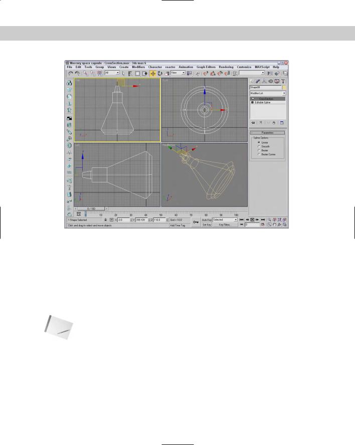
The CrossSection modifier works only on spline objects. This modifier connects the vertices of several cross-sectional splines together with another spline that runs along their edges like a backbone. The various cross-sectional splines can have different numbers of vertices. Parameters include different spline types such as Linear, Smooth, Bézier, and Bézier Corner.
To apply this modifier, all the cross-section splines need to belong to the same Editable Spline object. You can connect them using the Attach button. The cross-section splines are attached in the order they exist, which can be a problem if you create them in a different order. Figure 15-14 shows a spline network that has been created with the CrossSection modifier.
Note |
Editable Splines include a CrossSection feature that works just like the CrossSection modifier. |
Chapter 15 Creating and Editing Patches 449
Figure 15-14: The CrossSection modifier joins several cross-section splines into a network of splines ready for a surface.
Surface modifier
The Surface modifier is the other part of the surface tools. It creates a surface from several combined splines. It can use any spline network but works best with structures created with the CrossSection modifier. The surface created with this modifier is a patch surface.
Parameters for this modifier include a Spline Threshold value and options to Flip Normals, Remove Interior Patches, and Use Only Selected Segments. You can also specify the steps used to create the patch topology. After the surface is created, you can apply the Edit Patch modifier to further edit and refine the patch surface.
Note |
If the structure is already created, you can create a surface from the splines by simply apply- |
|
ing the Edit Patch modifier. |
Figure 15-15 shows the spline structure illustrated in the preceding figure with the Surface modifier applied.
Tutorial: Modeling a brass swan
Chapter 2 included a tutorial that added a background image of a brass swan to the viewports. In this tutorial, we use the CrossSection and Surface modifiers to create a swan based on these background images.
450 Part III Modeling
Figure 15-15: The Surface modifier applies a surface to the cross-section spline network.
To create a brass swan, follow these steps:
1.Open the Brass swan.max file from the Chap 15 directory on the CD-ROM. This file includes the background images needed to create the swan model.
2.Select Create Shapes Ellipse and drag in the Top viewport to create a simple ellipse that is roughly the shape of the swan’s nose. Use the transform tools to move, rotate, and scale the ellipse to match the cross section of the background image.
3.Hold down the Shift key and drag the ellipse shape to the base of the swan’s nose to create a clone. Use the transform tools to align this clone to the background image in the Front and Left viewports.
Note Although background images have been loaded for the Top, Front and Left viewports, you really only need two viewports to align all the cross sections. In this example, the Top viewport is misaligned with the other two viewports.
4.Continue to create cloned copies of the ellipse shape and match it to each changing cross section in the background images.
5.For the base cross sections, right-click on the ellipse shape and select Convert to Editable Spline from the pop-up quadmenu. Then click the Refine button and click the lower-left and lower-right corners of the ellipse to add two new vertices to the shape. Select and right-click these new vertices and change their vertex type to Bezier Corner to make the bottom of their cross section shapes flat.
Chapter 15 Creating and Editing Patches 451
6.Select the first cross section shape at the swan’s nose and convert it to an Editable Spline. Then click the Attach button and select each cloned cross section shape in order from the nose to the tail. This makes all the shapes part of the same Editable Spline object.
7.Choose Modifiers Patch/Spline Editing CrossSection to apply the CrossSection modifier to the Editable Spline object. Then choose Modifiers Patch/Spline Editing Surface to apply the Surface modifier. Next, enable the Flip Normals option to see the final space capsule. This command creates a surface that covers the spline framework. The surface that is created is a patch object.
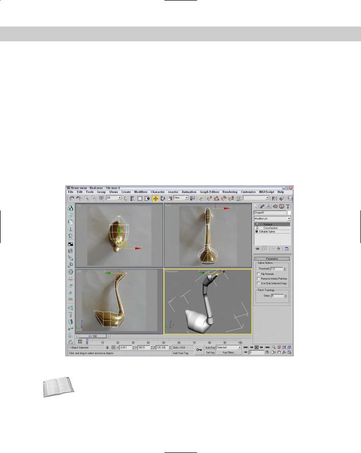
Figure 15-16 shows the completed swan model. Using the surface tools to create patch objects results in objects that are easy to modify. You can change any patch subobject by applying the Edit Patch modifier and using the rollouts in the Modify panel.
Another way to create this swan model is to use the CrossSection feature for the Editable Spline and then apply the Edit Patch modifier to create the finished surface. This method is cleaner and involves fewer modifiers.
Figure 15-16: The brass swan was created using the CrossSection and Surface modifiers.
Cross- |
Another common modifier that is used with patch objects is the PatchDeform modifier. |
Reference |
Learn more about this modifier in Chapter 30, “Animation Basics.” |
|