

- •Preface
- •About This Book
- •Acknowledgments
- •Contents at a Glance
- •Contents
- •Relaxing at the Beach
- •Dressing the Scene
- •Animating Motion
- •Rendering the Final Animation
- •Summary
- •The Interface Elements
- •Using the Menus
- •Using the Toolbars
- •Using the Viewports
- •Using the Command Panel
- •Using the Lower Interface Bar Controls
- •Interacting with the Interface
- •Getting Help
- •Summary
- •Understanding 3D Space
- •Using the Viewport Navigation Controls
- •Configuring the Viewports
- •Working with Viewport Backgrounds
- •Summary
- •Working with Max Scene Files
- •Setting File Preferences
- •Importing and Exporting
- •Referencing External Objects
- •Using the File Utilities
- •Accessing File Information
- •Summary
- •Customizing Modify and Utility Panel Buttons
- •Working with Custom Interfaces
- •Configuring Paths
- •Selecting System Units
- •Setting Preferences
- •Summary
- •Creating Primitive Objects
- •Exploring the Primitive Object Types
- •Summary
- •Selecting Objects
- •Setting Object Properties
- •Hiding and Freezing Objects
- •Using Layers
- •Summary
- •Cloning Objects
- •Understanding Cloning Options
- •Mirroring Objects
- •Cloning over Time
- •Spacing Cloned Objects
- •Creating Arrays of Objects
- •Summary
- •Working with Groups
- •Building Assemblies
- •Building Links between Objects
- •Displaying Links and Hierarchies
- •Working with Linked Objects
- •Summary
- •Using the Schematic View Window
- •Working with Hierarchies
- •Setting Schematic View Preferences
- •Using List Views
- •Summary
- •Working with the Transformation Tools
- •Using Pivot Points
- •Using the Align Commands
- •Using Grids
- •Using Snap Options
- •Summary
- •Exploring the Modifier Stack
- •Exploring Modifier Types
- •Summary
- •Exploring the Modeling Types
- •Working with Subobjects
- •Modeling Helpers
- •Summary
- •Drawing in 2D
- •Editing Splines
- •Using Spline Modifiers
- •Summary
- •Creating Editable Mesh and Poly Objects
- •Editing Mesh Objects
- •Editing Poly Objects
- •Using Mesh Editing Modifiers
- •Summary
- •Introducing Patch Grids
- •Editing Patches
- •Using Modifiers on Patch Objects
- •Summary
- •Creating NURBS Curves and Surfaces
- •Editing NURBS
- •Working with NURBS
- •Summary
- •Morphing Objects
- •Creating Conform Objects
- •Creating a ShapeMerge Object
- •Creating a Terrain Object
- •Using the Mesher Object
- •Working with BlobMesh Objects
- •Creating a Scatter Object
- •Creating Connect Objects
- •Modeling with Boolean Objects
- •Creating a Loft Object
- •Summary
- •Understanding the Various Particle Systems
- •Creating a Particle System
- •Using the Spray and Snow Particle Systems
- •Using the Super Spray Particle System
- •Using the Blizzard Particle System
- •Using the PArray Particle System
- •Using the PCloud Particle System
- •Using Particle System Maps
- •Controlling Particles with Particle Flow
- •Summary
- •Understanding Material Properties
- •Working with the Material Editor
- •Using the Material/Map Browser
- •Using the Material/Map Navigator
- •Summary
- •Using the Standard Material
- •Using Shading Types
- •Accessing Other Parameters
- •Using External Tools
- •Summary
- •Using Compound Materials
- •Using Raytrace Materials
- •Using the Matte/Shadow Material
- •Using the DirectX 9 Shader
- •Applying Multiple Materials
- •Material Modifiers
- •Summary
- •Understanding Maps
- •Understanding Material Map Types
- •Using the Maps Rollout
- •Using the Map Path Utility
- •Using Map Instances
- •Summary
- •Mapping Modifiers
- •Using the Unwrap UVW modifier
- •Summary
- •Working with Cameras
- •Setting Camera Parameters
- •Summary
- •Using the Camera Tracker Utility
- •Summary
- •Using Multi-Pass Cameras
- •Creating Multi-Pass Camera Effects
- •Summary
- •Understanding the Basics of Lighting
- •Getting to Know the Light Types
- •Creating and Positioning Light Objects
- •Viewing a Scene from a Light
- •Altering Light Parameters
- •Working with Photometric Lights
- •Using the Sunlight and Daylight Systems
- •Using Volume Lights
- •Summary
- •Selecting Advanced Lighting
- •Using Local Advanced Lighting Settings
- •Tutorial: Excluding objects from light tracing
- •Summary
- •Understanding Radiosity
- •Using Local and Global Advanced Lighting Settings
- •Working with Advanced Lighting Materials
- •Using Lighting Analysis
- •Summary
- •Using the Time Controls
- •Working with Keys
- •Using the Track Bar
- •Viewing and Editing Key Values
- •Using the Motion Panel
- •Using Ghosting
- •Animating Objects
- •Working with Previews
- •Wiring Parameters
- •Animation Modifiers
- •Summary
- •Understanding Controller Types
- •Assigning Controllers
- •Setting Default Controllers
- •Examining the Various Controllers
- •Summary
- •Working with Expressions in Spinners
- •Understanding the Expression Controller Interface
- •Understanding Expression Elements
- •Using Expression Controllers
- •Summary
- •Learning the Track View Interface
- •Working with Keys
- •Editing Time
- •Editing Curves
- •Filtering Tracks
- •Working with Controllers
- •Synchronizing to a Sound Track
- •Summary
- •Understanding Your Character
- •Building Bodies
- •Summary
- •Building a Bones System
- •Using the Bone Tools
- •Using the Skin Modifier
- •Summary
- •Creating Characters
- •Working with Characters
- •Using Character Animation Techniques
- •Summary
- •Forward versus Inverse Kinematics
- •Creating an Inverse Kinematics System
- •Using the Various Inverse Kinematics Methods
- •Summary
- •Creating and Binding Space Warps
- •Understanding Space Warp Types
- •Combining Particle Systems with Space Warps
- •Summary
- •Understanding Dynamics
- •Using Dynamic Objects
- •Defining Dynamic Material Properties
- •Using Dynamic Space Warps
- •Using the Dynamics Utility
- •Using the Flex Modifier
- •Summary
- •Using reactor
- •Using reactor Collections
- •Creating reactor Objects
- •Calculating and Previewing a Simulation
- •Constraining Objects
- •reactor Troubleshooting
- •Summary
- •Understanding the Max Renderers
- •Previewing with ActiveShade
- •Render Parameters
- •Rendering Preferences
- •Creating VUE Files
- •Using the Rendered Frame Window
- •Using the RAM Player
- •Reviewing the Render Types
- •Using Command-Line Rendering
- •Creating Panoramic Images
- •Getting Printer Help
- •Creating an Environment
- •Summary
- •Creating Atmospheric Effects
- •Using the Fire Effect
- •Using the Fog Effect
- •Summary
- •Using Render Elements
- •Adding Render Effects
- •Creating Lens Effects
- •Using Other Render Effects
- •Summary
- •Using Raytrace Materials
- •Using a Raytrace Map
- •Enabling mental ray
- •Summary
- •Understanding Network Rendering
- •Network Requirements
- •Setting up a Network Rendering System
- •Starting the Network Rendering System
- •Configuring the Network Manager and Servers
- •Logging Errors
- •Using the Monitor
- •Setting up Batch Rendering
- •Summary
- •Compositing with Photoshop
- •Video Editing with Premiere
- •Video Compositing with After Effects
- •Introducing Combustion
- •Using Other Compositing Solutions
- •Summary
- •Completing Post-Production with the Video Post Interface
- •Working with Sequences
- •Adding and Editing Events
- •Working with Ranges
- •Working with Lens Effects Filters
- •Summary
- •What Is MAXScript?
- •MAXScript Tools
- •Setting MAXScript Preferences
- •Types of Scripts
- •Writing Your Own MAXScripts
- •Learning the Visual MAXScript Editor Interface
- •Laying Out a Rollout
- •Summary
- •Working with Plug-Ins
- •Locating Plug-Ins
- •Summary
- •Low-Res Modeling
- •Using Channels
- •Using Vertex Colors
- •Rendering to a Texture
- •Summary
- •Max and Architecture
- •Using AEC Objects
- •Using Architectural materials
- •Summary
- •Tutorial: Creating Icy Geometry with BlobMesh
- •Tutorial: Using Caustic Photons to Create a Disco Ball
- •Summary
- •mental ray Rendering System
- •Particle Flow
- •reactor 2.0
- •Schematic View
- •BlobMesh
- •Spline and Patch Features
- •Import and Export
- •Shell Modifier
- •Vertex Paint and Channel Info
- •Architectural Primitives and Materials
- •Minor Improvements
- •Choosing an Operating System
- •Hardware Requirements
- •Installing 3ds max 6
- •Authorizing the Software
- •Setting the Display Driver
- •Updating Max
- •Moving Max to Another Computer
- •Using Keyboard Shortcuts
- •Using the Hotkey Map
- •Main Interface Shortcuts
- •Dialog Box Shortcuts
- •Miscellaneous Shortcuts
- •System Requirements
- •Using the CDs with Windows
- •What’s on the CDs
- •Troubleshooting
- •Index

Drawing and
Editing 2D Splines
and Shapes
Many modeling projects start from the ground up, and you can’t get much lower to the ground than 2D. But this book is on 3D
you say? What place is there for 2D shapes? Within the 3D world, you frequently encounter flat surfaces — the side of a building, the top of a table, a billboard, and so on. All these objects have flat 2D surfaces. Understanding how objects are composed of 2D surfaces will help as you start to build objects in 3D. This chapter examines the 2D elements of 3D objects and covers the tools needed to work with them.
Working in 2D in Max, you work with two general objects: splines and shapes. A spline is a special type of line that curves according to mathematical principles. In Max, splines are used to create all sorts of shapes such as circles, ellipses, and rectangles.
You can create splines and shapes using the Create Shapes menu, which opens the Shapes category on the Create panel. Just as with the other categories, several spline-based shape primitives are available. Spline shapes can be rendered, but they are normally used to create more advanced 3D geometric objects by extruding or lathing the spline. You can even find a whole group of modifiers that apply to splines. You can use splines to create animation paths as well as Loft and NURBS objects, and you will find that splines and shapes, although they are only 2D, are used frequently in Max.
Drawing in 2D
Shapes in Max are unique from other objects because they are drawn in 2D, which confines them to a single plane. That plane is defined by the viewport used to create the shape. For example, drawing a shape in the Top view constrains the shape to the XY plane, whereas drawing the shape in the Front view constrains it to the ZX plane. Even shapes drawn in the Perspective view are constrained to a plane such as the Home Grid.
You usually produce 2D shapes in a drawing package like Adobe Illustrator or CorelDRAW. Max supports importing line drawings using the AI format.
13C H A P T E R
In This Chapter
Working with shape primitives
Editing splines and shapes
Working with spline subobjects
Using spline modifiers
350 Part III Modeling
Cross- |
See Chapter 3, “Working with Files and XRefs,” to learn about importing AI files. |
Reference |
|
Whereas newly created or imported shapes are 2D and are confined to a single plane, splines can exist in 3D space. The Helix spline, for example, exists in 3D, having height as well as width values. Animation paths in particular typically move into 3D space.
Working with shape primitives
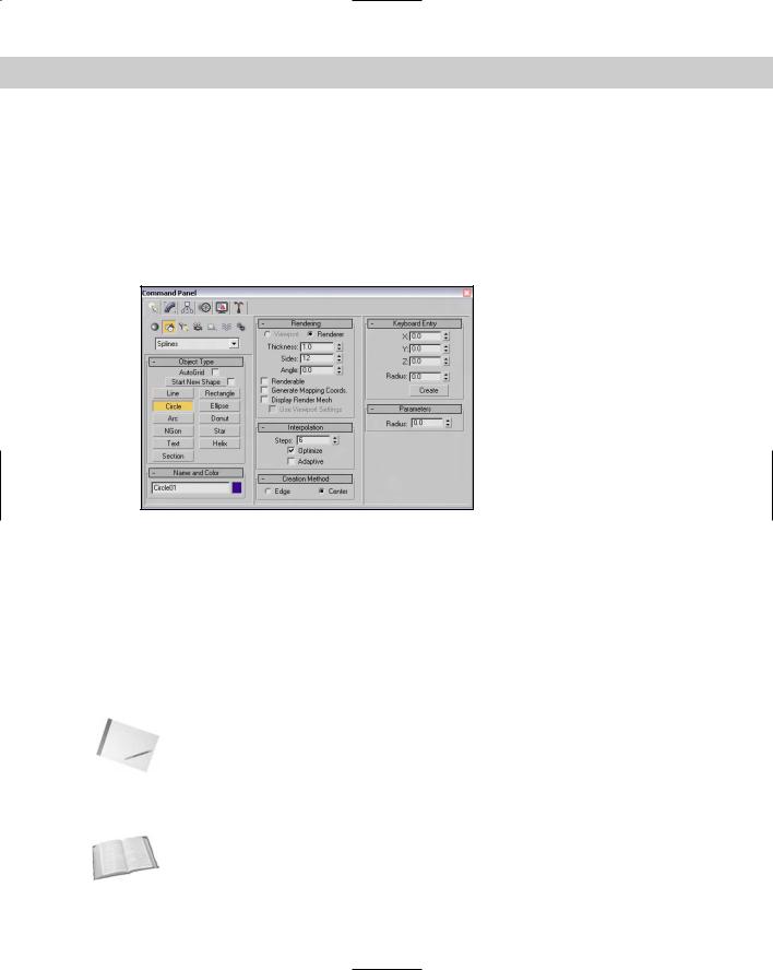
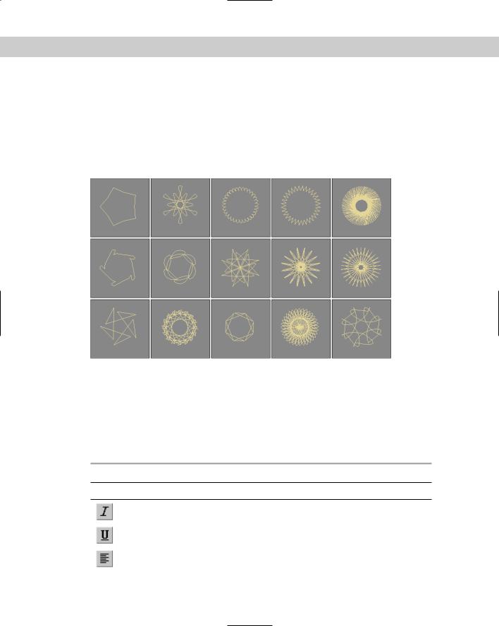
The shape primitive buttons that are displayed in the Object Type rollout of the Create panel when the Create Shapes menu is selected include many basic shapes, including Line, Circle, Arc, NGon (a polygon where you can set the number of sides), Text, Section, Rectangle, Ellipse, Donut, Star, and Helix, as shown in Figure 13-1. Clicking any of these shape buttons lets you create the shape by dragging in one of the viewports. After a shape is created, several new rollouts appear.
Figure 13-1: The shape primitives in all their 2D glory: Line, Circle, Arc, NGon, Text, Section, Rectangle, Ellipse, Donut, Star, and Helix.
Above the Shape buttons are two check boxes: AutoGrid and Start New Shape. AutoGrid creates a temporary grid, which you can use to align the shape with the surface of the nearest object under the mouse at the time of creation. This feature is helpful for starting a new spline on the surface of an object.
Cross- |
For more details on AutoGrid, see Chapter 10, “Transforming Objects — Translate, Rotate, and |
Reference |
Scale.” |
|
The Start New Shape option creates a new object with every new shape drawn in a viewport. Leaving this option unchecked lets you create compound shapes, which consist of several shapes used to create one object. Because compound shapes consist of several shapes, you
Chapter 13 Drawing and Editing 2D Splines and Shapes |
351 |
cannot edit them using the Parameters rollout. For example, if you want to write your name using splines, keep the Start New Shape option unselected to make all the letters part of the same object.
Just as with the Geometric primitives, every shape that is created is given a name and a color. You can change either of these in the Name and Color rollout.
Most of the shape primitives have several common rollouts: Rendering, Interpolation, Creation Method, Keyboard Entry, and Parameters, as shown in Figure 13-2. I cover these rollouts initially and then present the individual shape primitives.
Figure 13-2: These rollouts are common for most of the shape primitives.
Rendering rollout
The Rendering rollout includes options for making a spline a renderable object. Making a spline a renderable object converts the spline into a 3D object that is visible when you render the scene. For renderable objects, you can specify a Thickness, the number of Sides, and the Angle values. The Thickness is the diameter of the renderable spline. The number of Sides sets the number of sides that make up the cross section of the renderable spline. The lowest value that is possible is 3, which creates a triangle cross section. The Angle value determines where the corners of the cross section sides start, so you can set a three-sided spline to have a corner or an edge pointing upward. You can specify these values differently for the Viewport and the Renderer.
Note |
By default, a renderable spline has a 12-sided circle as its cross section. |
The Renderable option controls whether or not the spline is rendered with the scene. The Generate Mapping Coordinates option automatically generates mapping coordinates that are used to mark where a material map is placed.
Cross- |
To learn more about mapping coordinates, see Chapter 22, “Adding Material Details with Maps.” |
Reference |
|
352 Part III Modeling
Renderable splines appear as normal splines in the viewport unless the Display Render Mesh option is selected. If this option is selected, the Use Viewport Settings option is enabled, which lets you specify separate Thickness, Sides, and Angle values for the viewport. The Use Viewport Settings option lets you render the object using the Viewport settings instead of the Renderer settings.
Note |
The settings in the Rendering rollout apply to all new splines and shapes created in the scene. |
Interpolation rollout
In the Interpolation rollout, you can define the number of interpolation steps or segments that make up the shape. The Interpolation Steps value determines how many segments to include between vertices. For example, a circle shape with a Steps value of 0 has only 4 segments and looks like a diamond. Increasing the Steps value to 1 makes a circle out of eight segments. For shapes composed of straight lines (like the Rectangle and simple NGons), the Steps value is set to 0, but for a shape with many sides (like a Circle or Ellipse), the Steps value can have a big effect. Larger step values result in smoother curves.
The Adaptive option automatically sets the number of steps to produce a smooth curve. When the Adaptive option is enabled, the Steps and Optimize options become disabled. The Optimize option attempts to reduce the number of steps to produce a simpler spline by eliminating all the extra segments associated with the shape.
Note |
The Section and Helix shape primitives have no Interpolation rollout. |
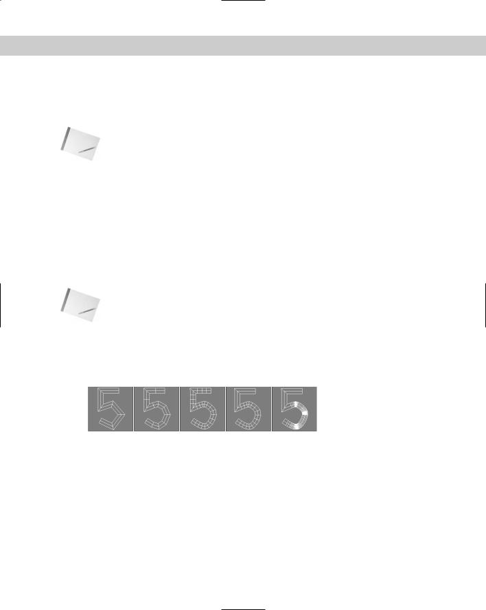
Figure 13-3 shows the number 5 drawn with the Line primitive in the Front viewport. The line has been made renderable in order to see the cross sections. The images from left to right show the line with Steps value of 0, 1, and 3. The fourth image has the Optimize option enabled. Notice that it uses only one segment for the straight edges. The fifth image has the Adaptive option enabled.
Figure 13-3: Using the Interpolation rollout, you can control the number of segments that make up a line.
Creation Method and Keyboard Entry rollouts
Most shape primitives also include Creation Method and Keyboard Entry rollouts (Text, Section, and Star are the exceptions). The Creation Method rollout offers options for specifying different ways to create the spline by dragging in a viewport, such as from edge to edge or from the center out. Table 13-1 lists the various creation method options for each of the shapes.

Chapter 13 Drawing and Editing 2D Splines and Shapes |
353 |
Table 13-1: Shape Primitive Creation Methods
Primitive |
Number of Viewport |
Default Creation |
|
Object |
Clicks to Create |
Method |
Other Creation Method |
|
|
|
|
Line |
2 to Infinite |
Corner Initial, Bézier |
Smooth, Initial, Corner, or |
|
|
Drag |
Smooth Drag |
Circle |
1 |
Center |
Edge |
Arc |
2 |
End-End-Middle |
Center-End-End |
Gon |
1 |
Center |
Edge |
Text |
1 |
none |
none |
Section |
1 |
none |
none |
Rectangle |
1 |
Edge |
Center |
Ellipse |
1 |
Edge |
Center |
Donut |
2 |
Center |
Edge |
Star |
2 |
none |
none |
Helix |
3 |
Center |
Edge |
|
|
|
|
Some shape primitives such as Star, Text, and Section don’t have any creation methods because Max offers only a single way to create these shapes.
The Keyboard Entry rollout offers a way to enter exact position and dimension values. After you enter the values, click the Create button to create the spline or shape in the active viewport. The settings are different for each shape.
The Parameters rollout includes such basic settings for the primitive as Radius, Length, and Width. You can alter these settings immediately after an object is created. However, after you deselect an object, the Parameters rollout moves to the Modify panel, and you must do any alterations to the shape there.
Line
The Line primitive includes several creation method settings, enabling you to create hard, sharp corners or smooth corners. You can set the Initial Type option to either Corner or Smooth to create a sharp or smooth corner for the first point created.
354 Part III Modeling
|
After clicking where the initial point is located, you can add additional points by clicking in |
|
the viewport. Dragging while creating a new point can make a point either a Corner, Smooth, |
|
or Bézier based on the Drag Type option selected in the Creation Method rollout. The curva- |
|
ture created by the Smooth option is determined by the distance between adjacent vertices, |
|
whereas you can control the curvature created by the Bézier option by dragging with the |
|
mouse a desired distance after the point is created. Bézier corners have control handles |
|
associated with them, enabling you to change their curvature. |
Tip |
Holding down the Shift key while clicking creates points that are vertically or horizontally at a |
|
right angle with the previous point. Holding down the Ctrl key snaps new points at an angle |
|
from the last segment, as determined by the Angle Snap setting. |
|
After creating all the points, you exit line mode by clicking the right mouse button. If the last |
|
point is on top of the first point, then a dialog box asks whether you want to close the spline. |
|
Click Yes to create a closed spline or No to continue adding points. Even after creating a closed |
|
spline, you can add more points to the current selection to create a compound shape if the |
|
Start New Shape option isn’t selected. If the first and last points don’t correspond, then an |
|
open spline is created. |
|
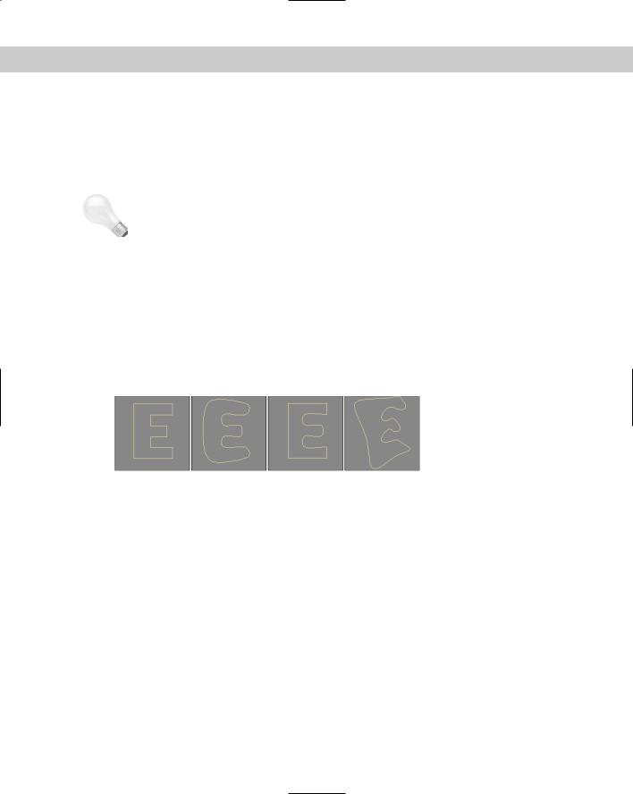
Figure 13-4 shows several splines created using the various creation method settings. The left |
|
spline was created with all the options set to Corner, and the second spline with all the |
|
options set to Smooth. The third spline uses the Corner Initial type and shows where drag- |
|
ging has smoothed many of the points. The last spline was created using the Bézier option. |
Figure 13-4: The Line shape can create various combinations of shapes with smooth and sharp corners.
In the Keyboard Entry rollout, you can add points by entering their X, Y, and Z dimensions and clicking the Add Point button. You can close the spline at any time by clicking the Close button or keep it open by clicking the Finish button.
Rectangle
The Rectangle shape produces simple rectangles. In the Parameters rollout, you can specify the Length and Width and also a Corner Radius. Holding down the Ctrl key while dragging creates a perfect square shape.
Circle
The Circle button creates — you guessed it — circles. The only adjustable parameter in the Parameters rollout is the Radius. All other rollouts are the same, as explained earlier. Circles created with the Circle button have only four vertices.
Chapter 13 Drawing and Editing 2D Splines and Shapes |
355 |
Ellipse
Ellipses are simple variations of the Circle shape. You define them by Length and Width values. Holding down the Ctrl key while dragging creates a perfect circle (or you can use the Circle shape).
Arc
The Arc primitive has two creation methods. Use the End-End-Middle method to create an arc shape by clicking and dragging to specify the two end points and then dragging to complete the shape. Use the Center-End-End method to create an arc shape by clicking and dragging from the center to one of the end points and then dragging the arc length to the second end point.
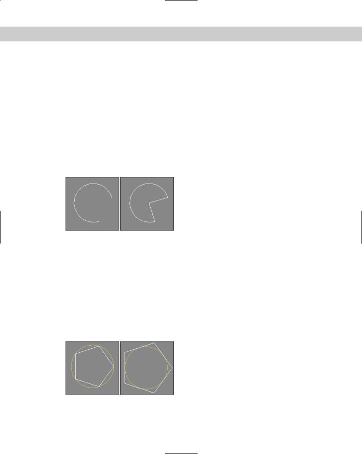
Other parameters include the Radius and the From and To settings, where you can enter the value in degrees for the start and end of the arc. The Pie Slice option connects the end points of the arc to its center to create a pie-sliced shape, as shown in Figure 13-5. The Reverse option lets you reverse the arc’s direction.
Figure 13-5: Enabling the Pie Slice option connects the arc ends with the center of the circle.
Donut
As another variation of the Circle shape, the Donut shape consists of two concentric circles; you can create it by dragging once to specify the outer circle and again to specify the inner circle. The parameters for this object are simply two radii.
NGon
The NGon shape lets you create regular polygons by specifying the Number of Sides and the Corner Radius. You can also specify whether the NGon is Inscribed or Circumscribed, as shown in Figure 13-6. Inscribed polygons are positioned within a circle that touches all the outer polygon’s vertices. Circumscribed polygons are positioned outside of a circle that touches the midpoint of each polygon edge. The Circular option changes the polygon to a circle that inscribes the polygon.
Figure 13-6: An inscribed pentagon and a circumscribed pentagon
356 Part III Modeling
Star
The Star shape also includes two radii values — the larger Radius value defines the distance of the outer points of the Star shape from its center, and the smaller Radius value is the distance from the center of the star to the inner points. The Point setting indicates the number of points. This value can range from 3 to 100. The Distortion value causes the inner points to rotate relative to the outer points and can be used to create some interesting new star types. The Fillet Radius 1 and Fillet Radius 2 values adjust the Fillet for the inner and outer points.
Figure 13-7 shows a sampling of what is possible with the Star shapes.
Figure 13-7: The Star primitive can be changed to create some amazing shapes.
Text
You can use the Text primitive to add outlined text to the scene. In the Parameters rollout, you can specify a Font by choosing one from the drop-down list at the top of the Parameters rollout. Under the Font drop-down list are six icons, shown in Table 13-2. The left two icons are for the Italic and Underline styles. Selecting either of these styles applies the style to all the text. The right four icons are for aligning the text to the left, centered, right, or justified.
|
Table 13-2: Text Font Attributes |
Icon |
Description |
|
Italic |
|
Underline |
|
Left |
Chapter 13 Drawing and Editing 2D Splines and Shapes |
357 |
Icon |
Description |
|
Centered |
|
Right |
|
Justified |
Note |
The list of available fonts includes only the Windows TrueType fonts and Type 1 PostScript fonts |
|
installed on your system and any extra fonts located in the font path listed in the Configure |
|
Paths dialog box. You need to restart Max before the fonts in the font path are recognized. |
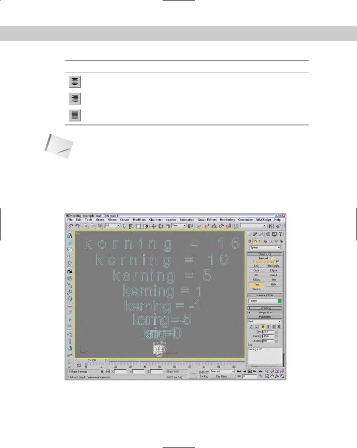
The size of the text is determined by the Size value. The Kerning (which is the space between adjacent characters) and Leading (which is the space between adjacent lines of text) values can actually be negative. Setting the Kerning value to a large negative number actually displays the text backwards. Figure 13-8 shows an example of some text and an example of kerning values in the Max interface.
Figure 13-8: The Text shape lets you control the space between letters, known as kerning.
358 Part III Modeling
You can type the text to be created in the text area. You can cut, copy, and paste text into this text area from an external application if you right-click on the text area. After setting the parameters and typing the text, the text appears as soon as you click in one of the viewports. The Text is updated automatically when any of the parameters (including the text) is changed. To turn off automatic updating, select the Manual Update toggle. You can then update with the Update button.
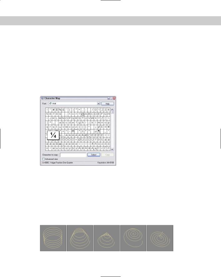
To enter special characters into the text area, hold down the Alt key while typing the character code using the numeric keypad. For example, type 0188 in the numeric keypad with the Alt key held down and the 1/4 symbol appears. If you open the Character Map application, you can see a complete list of special characters and the number combinations that make them appear. The Character Map application, seen in Figure 13-9, can be opened in Windows by selecting Start All Programs Accessories System Tools Character Map.
Figure 13-9: The Character Map application shows all the special characters that are available.
Helix
A Helix is like a spring coil shape, and it is the one shape of all the Shape primitives that exists in 3D. Helix parameters include two radii for specifying the inner and outer radius. These two values can be equal to create a coil or unequal to create a spiral. Parameters also exist for the Height and number of Turns. The Bias parameter causes the Helix turns to be gathered all together at the top or bottom of the shape. The CW and CCW options let you specify whether the Helix turns clockwise or counterclockwise.
Figure 13-10 shows a sampling of Helix shapes: The first Helix has equal radii values, the second one has a smaller second radius, the third Helix spirals to a second radius value of 0, and the last two Helix objects have Bias values of 0.8 and –0.8.
Figure 13-10: The Helix shape can be straight or spiral shaped.
Chapter 13 Drawing and Editing 2D Splines and Shapes |
359 |
Section
Section stands for cross section. The Section shape is a cross section of the edges of any 3D object through which the Section’s cutting plane passes. The process consists of dragging in the viewport to create a cross-sectioning plane. You can then move, rotate, or scale the crosssectioning plane to obtain the desired cross section. In the Section Parameters rollout is a Create Shape button. Clicking this button opens a dialog box where you can name the new shape. You can use one Section object to create multiple shapes.
Note |
You can make sections only from intersecting a 3D object. If the cross-sectioning plane doesn’t |
|
intersect the 3D object, then it won’t create a shape. You cannot use the Section primitive on |
|
shapes, even if it is a renderable spline. |
The Parameters rollout includes settings for updating the Section shape. You can update it when the Section plane moves, when the Section is selected, or Manually (using the Update Section button). You can also set the Section Extents to Infinite, Section Boundary, or Off. The Infinite setting creates the cross-section spline as if the cross-sectioning plane were of infinite size, whereas the Section Boundary limits the plane’s extents to the boundaries of the visible plane. The color swatch determines the color of the intersecting shape.
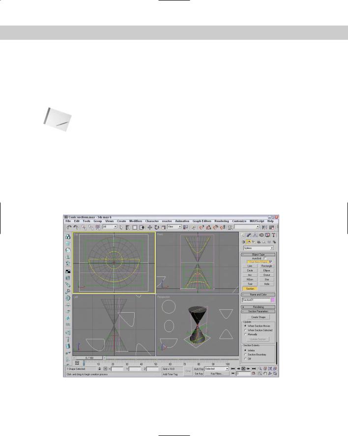
To give you an idea of what the Section shape can produce, Figure 13-11 shows the shapes resulting from sectioning two Cone objects, including a circle, an ellipse, a parabola, and a hyperbole. The shapes have been moved to the sides to be more visible.
Figure 13-11: You can use the Section shape primitive to create the conic sections (circle, ellipse, parabola, hyperbola) from a set of 3D cones.
360 Part III Modeling
Tutorial: Drawing a company logo
One of the early uses for 3D graphics was to animate corporate logos, and although Max can still do this without any problems, it now has capabilities far beyond those available in the early days. One can even use the Shape tools to help design the logo. In this example, we design and create a simple logo using the Shape tools for the fictitious company named Expeditions South.
To use the Shape tools to design and create a company logo, follow these steps:
1.Start by creating a four-pointed star. Click the Star button, and drag in the Top view to create a shape. Change the parameters for this star as follows: Radius1 = 60, Radius2 = 20, and Points = 4.
2.Select and move the star shape to the left side of the viewport.
3.Now click the Text button. Change the font to Impact and the Size to 50. In the Text area, type Expeditions South and include a line return and several spaces between the two words so they are offset. Click in the Top viewport to place the text.
4.Use the Select and Move button (W) to reposition the text next to the Star shape.
5.Click the Line button, and create several short highlighting lines around the bottom point of the star.
The finished logo is now ready to extrude and animate. Figure 13-12 shows the results.
Figure 13-12: A company logo created entirely in Max using shapes
Chapter 13 Drawing and Editing 2D Splines and Shapes |
361 |
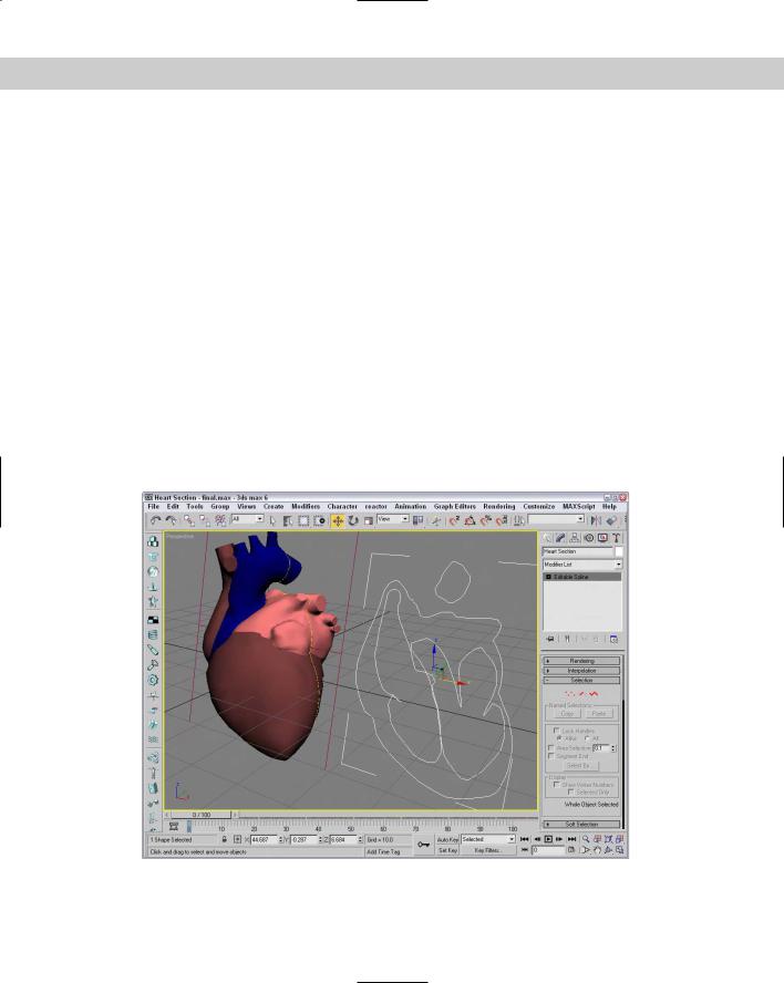
Tutorial: Viewing the interior of a heart
As an example of the Section primitive, let’s explore a section of a Heart model. The model was created by Viewpoint Datalabs and is very realistic — so realistic, in fact, that it could be used to teach medical students the inner workings of the heart.
To create a spline from the cross section of the heart, follow these steps:
1.Open the Heart section.max file from the Chap 13 directory on the CD-ROM. This file includes a physical model of a heart created by Viewpoint Datalabs.
2.Select Create Shapes Section and drag a plane in the Front viewport that is large enough to cover the heart.
This plane is your cross-sectioning plane.
3.Select the Select and Rotate button on the main toolbar (or press the E key), and rotate the cross-sectioning plane to cross the heart at the desired angle.
4.In the Parameters rollout, click the Create Shape button and give the new shape the name Heart Section.
5.From the Select by Name dialog box (opened with the H key), select the section by name, separate it from the model, and reposition it to be visible.
Figure 13-13 shows the resulting model and section.
Figure 13-13: You can use the Section shape to view the interior area of the heart.