

- •Preface
- •About This Book
- •Acknowledgments
- •Contents at a Glance
- •Contents
- •Relaxing at the Beach
- •Dressing the Scene
- •Animating Motion
- •Rendering the Final Animation
- •Summary
- •The Interface Elements
- •Using the Menus
- •Using the Toolbars
- •Using the Viewports
- •Using the Command Panel
- •Using the Lower Interface Bar Controls
- •Interacting with the Interface
- •Getting Help
- •Summary
- •Understanding 3D Space
- •Using the Viewport Navigation Controls
- •Configuring the Viewports
- •Working with Viewport Backgrounds
- •Summary
- •Working with Max Scene Files
- •Setting File Preferences
- •Importing and Exporting
- •Referencing External Objects
- •Using the File Utilities
- •Accessing File Information
- •Summary
- •Customizing Modify and Utility Panel Buttons
- •Working with Custom Interfaces
- •Configuring Paths
- •Selecting System Units
- •Setting Preferences
- •Summary
- •Creating Primitive Objects
- •Exploring the Primitive Object Types
- •Summary
- •Selecting Objects
- •Setting Object Properties
- •Hiding and Freezing Objects
- •Using Layers
- •Summary
- •Cloning Objects
- •Understanding Cloning Options
- •Mirroring Objects
- •Cloning over Time
- •Spacing Cloned Objects
- •Creating Arrays of Objects
- •Summary
- •Working with Groups
- •Building Assemblies
- •Building Links between Objects
- •Displaying Links and Hierarchies
- •Working with Linked Objects
- •Summary
- •Using the Schematic View Window
- •Working with Hierarchies
- •Setting Schematic View Preferences
- •Using List Views
- •Summary
- •Working with the Transformation Tools
- •Using Pivot Points
- •Using the Align Commands
- •Using Grids
- •Using Snap Options
- •Summary
- •Exploring the Modifier Stack
- •Exploring Modifier Types
- •Summary
- •Exploring the Modeling Types
- •Working with Subobjects
- •Modeling Helpers
- •Summary
- •Drawing in 2D
- •Editing Splines
- •Using Spline Modifiers
- •Summary
- •Creating Editable Mesh and Poly Objects
- •Editing Mesh Objects
- •Editing Poly Objects
- •Using Mesh Editing Modifiers
- •Summary
- •Introducing Patch Grids
- •Editing Patches
- •Using Modifiers on Patch Objects
- •Summary
- •Creating NURBS Curves and Surfaces
- •Editing NURBS
- •Working with NURBS
- •Summary
- •Morphing Objects
- •Creating Conform Objects
- •Creating a ShapeMerge Object
- •Creating a Terrain Object
- •Using the Mesher Object
- •Working with BlobMesh Objects
- •Creating a Scatter Object
- •Creating Connect Objects
- •Modeling with Boolean Objects
- •Creating a Loft Object
- •Summary
- •Understanding the Various Particle Systems
- •Creating a Particle System
- •Using the Spray and Snow Particle Systems
- •Using the Super Spray Particle System
- •Using the Blizzard Particle System
- •Using the PArray Particle System
- •Using the PCloud Particle System
- •Using Particle System Maps
- •Controlling Particles with Particle Flow
- •Summary
- •Understanding Material Properties
- •Working with the Material Editor
- •Using the Material/Map Browser
- •Using the Material/Map Navigator
- •Summary
- •Using the Standard Material
- •Using Shading Types
- •Accessing Other Parameters
- •Using External Tools
- •Summary
- •Using Compound Materials
- •Using Raytrace Materials
- •Using the Matte/Shadow Material
- •Using the DirectX 9 Shader
- •Applying Multiple Materials
- •Material Modifiers
- •Summary
- •Understanding Maps
- •Understanding Material Map Types
- •Using the Maps Rollout
- •Using the Map Path Utility
- •Using Map Instances
- •Summary
- •Mapping Modifiers
- •Using the Unwrap UVW modifier
- •Summary
- •Working with Cameras
- •Setting Camera Parameters
- •Summary
- •Using the Camera Tracker Utility
- •Summary
- •Using Multi-Pass Cameras
- •Creating Multi-Pass Camera Effects
- •Summary
- •Understanding the Basics of Lighting
- •Getting to Know the Light Types
- •Creating and Positioning Light Objects
- •Viewing a Scene from a Light
- •Altering Light Parameters
- •Working with Photometric Lights
- •Using the Sunlight and Daylight Systems
- •Using Volume Lights
- •Summary
- •Selecting Advanced Lighting
- •Using Local Advanced Lighting Settings
- •Tutorial: Excluding objects from light tracing
- •Summary
- •Understanding Radiosity
- •Using Local and Global Advanced Lighting Settings
- •Working with Advanced Lighting Materials
- •Using Lighting Analysis
- •Summary
- •Using the Time Controls
- •Working with Keys
- •Using the Track Bar
- •Viewing and Editing Key Values
- •Using the Motion Panel
- •Using Ghosting
- •Animating Objects
- •Working with Previews
- •Wiring Parameters
- •Animation Modifiers
- •Summary
- •Understanding Controller Types
- •Assigning Controllers
- •Setting Default Controllers
- •Examining the Various Controllers
- •Summary
- •Working with Expressions in Spinners
- •Understanding the Expression Controller Interface
- •Understanding Expression Elements
- •Using Expression Controllers
- •Summary
- •Learning the Track View Interface
- •Working with Keys
- •Editing Time
- •Editing Curves
- •Filtering Tracks
- •Working with Controllers
- •Synchronizing to a Sound Track
- •Summary
- •Understanding Your Character
- •Building Bodies
- •Summary
- •Building a Bones System
- •Using the Bone Tools
- •Using the Skin Modifier
- •Summary
- •Creating Characters
- •Working with Characters
- •Using Character Animation Techniques
- •Summary
- •Forward versus Inverse Kinematics
- •Creating an Inverse Kinematics System
- •Using the Various Inverse Kinematics Methods
- •Summary
- •Creating and Binding Space Warps
- •Understanding Space Warp Types
- •Combining Particle Systems with Space Warps
- •Summary
- •Understanding Dynamics
- •Using Dynamic Objects
- •Defining Dynamic Material Properties
- •Using Dynamic Space Warps
- •Using the Dynamics Utility
- •Using the Flex Modifier
- •Summary
- •Using reactor
- •Using reactor Collections
- •Creating reactor Objects
- •Calculating and Previewing a Simulation
- •Constraining Objects
- •reactor Troubleshooting
- •Summary
- •Understanding the Max Renderers
- •Previewing with ActiveShade
- •Render Parameters
- •Rendering Preferences
- •Creating VUE Files
- •Using the Rendered Frame Window
- •Using the RAM Player
- •Reviewing the Render Types
- •Using Command-Line Rendering
- •Creating Panoramic Images
- •Getting Printer Help
- •Creating an Environment
- •Summary
- •Creating Atmospheric Effects
- •Using the Fire Effect
- •Using the Fog Effect
- •Summary
- •Using Render Elements
- •Adding Render Effects
- •Creating Lens Effects
- •Using Other Render Effects
- •Summary
- •Using Raytrace Materials
- •Using a Raytrace Map
- •Enabling mental ray
- •Summary
- •Understanding Network Rendering
- •Network Requirements
- •Setting up a Network Rendering System
- •Starting the Network Rendering System
- •Configuring the Network Manager and Servers
- •Logging Errors
- •Using the Monitor
- •Setting up Batch Rendering
- •Summary
- •Compositing with Photoshop
- •Video Editing with Premiere
- •Video Compositing with After Effects
- •Introducing Combustion
- •Using Other Compositing Solutions
- •Summary
- •Completing Post-Production with the Video Post Interface
- •Working with Sequences
- •Adding and Editing Events
- •Working with Ranges
- •Working with Lens Effects Filters
- •Summary
- •What Is MAXScript?
- •MAXScript Tools
- •Setting MAXScript Preferences
- •Types of Scripts
- •Writing Your Own MAXScripts
- •Learning the Visual MAXScript Editor Interface
- •Laying Out a Rollout
- •Summary
- •Working with Plug-Ins
- •Locating Plug-Ins
- •Summary
- •Low-Res Modeling
- •Using Channels
- •Using Vertex Colors
- •Rendering to a Texture
- •Summary
- •Max and Architecture
- •Using AEC Objects
- •Using Architectural materials
- •Summary
- •Tutorial: Creating Icy Geometry with BlobMesh
- •Tutorial: Using Caustic Photons to Create a Disco Ball
- •Summary
- •mental ray Rendering System
- •Particle Flow
- •reactor 2.0
- •Schematic View
- •BlobMesh
- •Spline and Patch Features
- •Import and Export
- •Shell Modifier
- •Vertex Paint and Channel Info
- •Architectural Primitives and Materials
- •Minor Improvements
- •Choosing an Operating System
- •Hardware Requirements
- •Installing 3ds max 6
- •Authorizing the Software
- •Setting the Display Driver
- •Updating Max
- •Moving Max to Another Computer
- •Using Keyboard Shortcuts
- •Using the Hotkey Map
- •Main Interface Shortcuts
- •Dialog Box Shortcuts
- •Miscellaneous Shortcuts
- •System Requirements
- •Using the CDs with Windows
- •What’s on the CDs
- •Troubleshooting
- •Index
692 Part VI Lighting
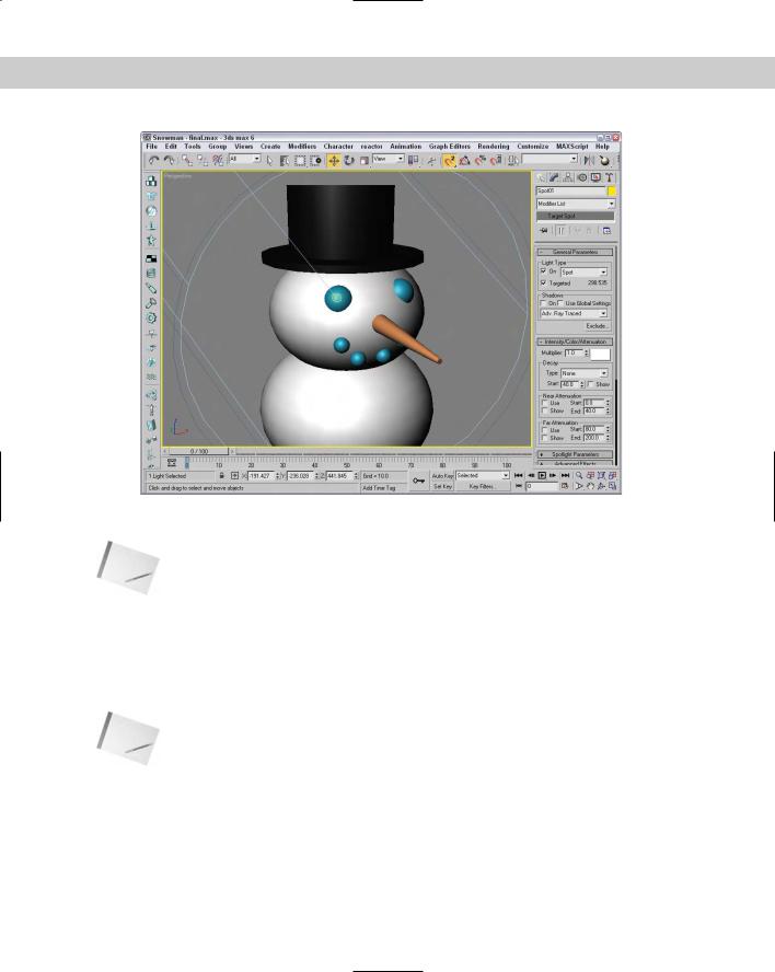
Figure 27-5: The snowman, after the lights have been automatically repositioned using the Place Highlights command
Note |
The effect of lights cannot be fully seen in the viewport. To see the rendered result of a light, |
|
render the scene or view the scene in the ActiveShade window. You can open the |
|
ActiveShade window with the Rendering ActiveShade Floater menu command. |
Viewing a Scene from a Light
You can configure viewports to display the view from any light, with the exception of an Omni light. To do so, right-click the viewport title, and select Views and the light name at the top of the pop-up menu.
Note The keyboard shortcut for making the active viewport a Light view is the $ (the dollar sign that appears above the 4) key. If more than one light exists, then the Select Light dialog box appears and lets you select which light to use. This can be used only on spot and direct lights.
Chapter 27 Basic Lighting Techniques 693
Light viewport controls
When a viewport is changed to show a light view, the Viewport Navigation buttons in the lower-right corner of the screen change into Light Navigation controls. Table 27-1 describes these controls.
Note Many of these controls are identical for viewports displaying lights or cameras.
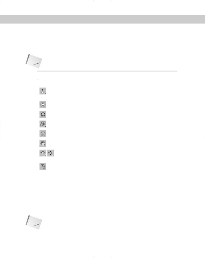
Table 27-1: Light Navigation Control Buttons
Toolbar Button |
Name |
Description |
|
|
|
|
Dolly, Target, Both |
Moves the light, its target, or both the light and |
|
|
its target closer to or farther away from the scene |
|
|
in the direction it is pointing. |
|
Light Hotspot |
Adjusts the angle of the light’s hotspot, which is |
|
|
displayed as a blue cone. |
|
Roll Light |
Spins the light about its local Z axis. |
|
Zoom Extents All, |
Zooms in on all objects or the selected objects |
|
Zoom Extents All Selected |
until they fill the viewport. |
|
Light Falloff |
Changes the angle of the light’s falloff cone. |
|
Truck Light |
Moves the light perpendicular to the line of sight. |
|
Orbit, Pan Light |
The Orbit button rotates the light around the |
|
|
target, whereas the Pan Light button rotates the |
|
|
target around the light. |
|
Min/Max Toggle |
Makes the current viewport fill the screen. |
|
|
Clicking this button a second time returns the |
|
|
display to several viewports. |
|
|
|
If you hold down the Ctrl key while using the Light Hotspot or Falloff buttons, Max maintains the distance between the hotspot and falloff cones. The Hotspot cone cannot grow any larger than the Falloff cone.
You can constrain any light movements to a single axis by holding down the Shift key. The Ctrl key causes the movements to increase rapidly.
For Free lights, an invisible target is determined by the distance computed from the other light properties. You can use the Shift key to constrain rotations to be vertical or horizontal.
Note |
You can undo changes in the normal viewports using the Views Undo command, but you |
|
undo light viewport changes with the regular Edit Undo command. |
694 Part VI Lighting
Tutorial: Lighting a lamp
To practice using lights, let’s try to get a lamp model to work as it should.
To add a light to a lamp model, follow these steps:
1.Open the Lamp.max from the Chap 27 directory on the CD-ROM.
This file includes a lamp mesh surrounded by some plane objects used to create the walls and floor. The lamp model was created by Zygote Media. It looks like a standard living room lamp that you could buy in any department store.
2.Select the Create Lights Standard Lights Omni menu command, and click in any viewport.
3.Use the Select and Move transform button (W) to position the light object inside the lamp’s light bulb.
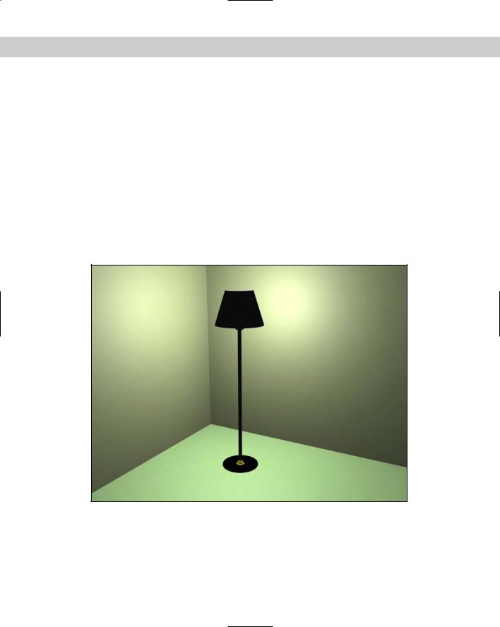
The resulting image is shown in Figure 27-6. Notice that the light intensity is greater at places closer to the light.
Figure 27-6: The rendered lighted-lamp image
Chapter 27 Basic Lighting Techniques 695
Altering Light Parameters
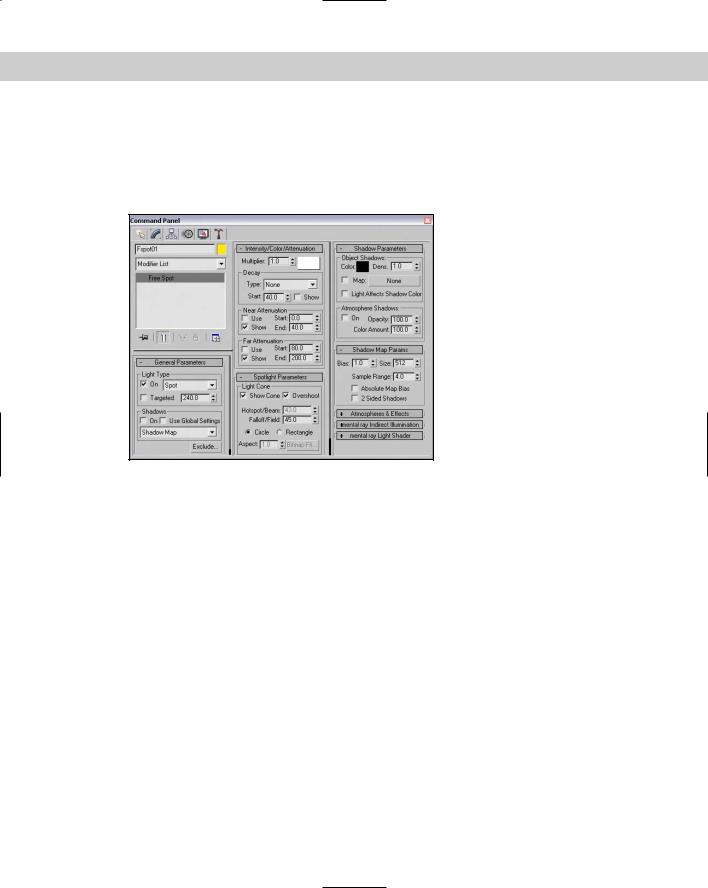
Lights affect every object in a scene and can really make or break a rendered image, so it shouldn’t be surprising that each light comes with many controls and parameters. Several different rollouts work with lights, as shown in Figure 27-7.
Figure 27-7: The various light rollouts control parameters and shadows.
If you’re looking for a light switch to turn lights on and off, look no further than the Modify panel. When a light is selected, several different rollouts appear. The options contained in these rollouts enable you to turn the lights on and off, select a light color and intensity, and determine how a light affects object surfaces.
General parameters
The Light Type drop-down list in the General Parameters rollout lets you change the type of light instantly, so that you can switch from Omni light to Spotlight with little effort. You can also switch between targeted and untargeted lights. To the right of the Targeted option is the distance in scene units between the light and the target. This feature provides an easy way to look at the results of using a different type of light. When you change the type of light, you lose the settings for the previous light.
The General Parameters rollout also includes some settings for shadows. Shadows can be easily turned on or off. In this rollout, you can defer to the global settings by selecting the Use Global Settings option. This option helps to maintain consistent settings across several lights. It applies the same settings to all lights, so that changing the value for one light changes that same value for all lights that have this option selected.
696 Part VI Lighting
You can also select from a drop-down list whether the shadows are created using Area Shadows, a Shadow Map, regular or advanced raytraced shadows, or a mental ray shadow map. A new rollout appears depending on the selection that you make.
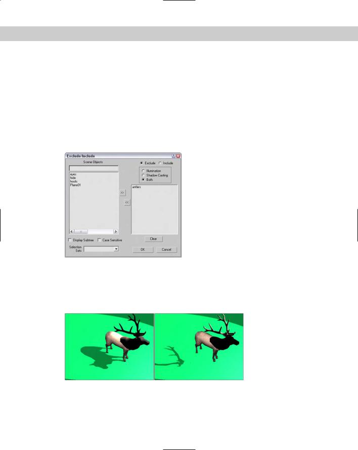
The Exclude button opens the Exclude/Include dialog box, where you can select objects to be included or excluded from illumination and/or shadows. The pane on the left includes a list of all the current objects in the scene. To exclude objects from being lit, select the Exclude option, select the objects to be excluded from the pane on the left, and click the double arrow icon pointing to the right to move the objects to the pane on the right.
Figure 27-8 shows the Exclude/Include dialog box. This dialog box also recognizes any Selection Sets that you’ve previously defined. You select them from the Selection Sets dropdown list.
Figure 27-8: The Exclude/Include dialog box lets you set which objects are excluded or included from being illuminated.
As an example of the Exclude/Include feature, Figure 27-9 shows the elk model with the antlers (left) and its body (right) excluded from the shadows pass.
Figure 27-9: Using the Exclude/Include dialog box, you can exclude objects from casting shadows.
Chapter 27 Basic Lighting Techniques 697
The Intensity/Color/Attenuation rollout
In the Intensity/Color/Attenuation rollout, the Multiplier value controls the light intensity. A light with a Multiplier set to 2 is twice as bright as a light with its Multiplier set to 1. Higher Multiplier values make a light appear white regardless of the light color. The Multiplier value can also be negative. A negative value can be used to pull light from a scene, but should be used with caution.
Tip |
Adding and positioning another light typically is better than increasing the multiplier. |
To the right of the Multiplier value is a color swatch. Clicking the color swatch opens a color selector where you can choose a new light color.
Attenuation is a property that determines how light fades over distance. An example of this is a candle set in a room. The farther you get from the candle, the less the light shines.
You use three basic parameters to simulate realistic attenuation. Near Attenuation sets the distance at which the light begins to fade, and Far Attenuation sets the distance at which the light falls to 0. Both these properties are ranges that include Start and End values. The third parameter sets the Decay value, which simulates attenuation using a mathematical formula to compute the drop in light intensity over time.
Selecting the Use option enables the Near and Far Attenuation values; both have Start and End values that set the range for these attenuation types. The Show option makes the attenuation distances and decay values visible in the viewports. The three types of decay from which you can choose are None, Inverse, and Inverse Square. The Inverse type decays linearly with the distance away from the light. The Inverse Square type decays exponentially with distance.
Note The Inverse Square type approximates real lights the best, but it is often too dim for computer graphic images. You can compensate for this by increasing the Multiplier value.
Spotlight and directional light parameters
The Spotlight Parameters rollout includes values to set the angular distance of both the Hot Spot and Falloff cones. The Show Cone option makes the Hotspot and Falloff cones visible in the viewport when the light is not selected. The Overshoot option makes the light shine in all directions like an Omni light, but projections and shadows occur only within the Falloff cone. You can also set the light shape to be circular or rectangular. For a rectangular-shaped spotlight, you can control the aspect ratio. You can use the Bitmap Fit button to make the aspect ratio match a particular bitmap.
The Directional Light Parameters rollout, which appears for Direct light types, is identical to the Spotlight Parameters rollout and also includes settings for the Hot Spot and Falloff values.
Advanced Effects
Options in the Affect Surface section of the Advanced Effects rollout control how light interacts with an object’s surface. The Contrast value alters the contrast between the diffuse and the ambient surface areas. The Soften Diffuse Edge value blurs the edges between the diffuse
698 Part VI Lighting
and ambient areas of a surface. The Diffuse and Specular options let you disable these properties of an object’s surface. When the Ambient Only option is turned on, the light affects only the ambient properties of the surface.
Cross- |
Find more detail on the Diffuse, Specular, and Ambient properties in Chapter 19, “Exploring |
Reference |
the Material Editor.” |
|
You can use any light as a projector; you find this option in the Advance Effects rollouts. Selecting the Map option enables you to use the light as a projector. You can select a map to project by clicking the button to the right of the map option. You can drag a material map directly from the Material/Map Browser onto the Projector Map button.
Shadow parameters
All light types have a Shadow Parameters rollout that you can use to select a shadow color by clicking the color swatch. The default color is black. The Dens setting stands for “Density” and controls how dark the shadow appears. Lower values produce light shadows, and higher values produce dark shadows. This value can also be negative.
The Map option, like the Projection Map, can be used to project a map along with the shadow color. The Light Affects Shadow Color option alters the Shadow Color by blending it with the light color if selected.
In the Atmosphere Shadows section, the On button lets you determine whether atmospheric effects, such as fog, can cast shadows. You can also control the Opacity and the degree to which atmospheric colors blend with the Shadow Color.
When you select a light and open the Modify panel, one additional rollout is available: the Atmospheres and Effects rollout. This rollout is a shortcut to the Environment dialog box, where you can specify atmospheric effects such as fog and volume lights.
Cross- |
Chapter 42, “Using Atmospheric Effects,” covers atmospheric effects. |
Reference |
|
If the Area Shadows option is selected in the General Parameters rollout, then the Area Shadows rollout appears, which includes several settings for controlling this shadow type. In the drop-down list at the top of the rollout, you can select from several Basic Options including Simple, Rectangle Light, Disc Light, Box Light, and Sphere Light. You can select dimensions depending on which option is selected. You can also set the Integrity, Quality, Spread, Bias, and Jitter amounts.
For the Shadow Map option, the Shadow Map Params rollout includes values for the Bias, Size, and Sample Range. The Sample Range value softens the shadow edges. You can also select to use an Absolute Map Bias and 2 Sided Shadows.
If the Ray Traced Shadows option is selected in the Shadow Parameters rollout, the Ray Traced Shadows Parameters rollout appears below it. This simple rollout includes only two values: Bias and Max Quadtree Depth. The Bias settings cause the shadow to move toward or away from the object that casts the shadow. The Max Quadtree Depth determines the accuracy of the shadows by controlling how long the ray paths are followed. There is also an option to enable 2 Sided Shadows.