

- •Preface
- •About This Book
- •Acknowledgments
- •Contents at a Glance
- •Contents
- •Relaxing at the Beach
- •Dressing the Scene
- •Animating Motion
- •Rendering the Final Animation
- •Summary
- •The Interface Elements
- •Using the Menus
- •Using the Toolbars
- •Using the Viewports
- •Using the Command Panel
- •Using the Lower Interface Bar Controls
- •Interacting with the Interface
- •Getting Help
- •Summary
- •Understanding 3D Space
- •Using the Viewport Navigation Controls
- •Configuring the Viewports
- •Working with Viewport Backgrounds
- •Summary
- •Working with Max Scene Files
- •Setting File Preferences
- •Importing and Exporting
- •Referencing External Objects
- •Using the File Utilities
- •Accessing File Information
- •Summary
- •Customizing Modify and Utility Panel Buttons
- •Working with Custom Interfaces
- •Configuring Paths
- •Selecting System Units
- •Setting Preferences
- •Summary
- •Creating Primitive Objects
- •Exploring the Primitive Object Types
- •Summary
- •Selecting Objects
- •Setting Object Properties
- •Hiding and Freezing Objects
- •Using Layers
- •Summary
- •Cloning Objects
- •Understanding Cloning Options
- •Mirroring Objects
- •Cloning over Time
- •Spacing Cloned Objects
- •Creating Arrays of Objects
- •Summary
- •Working with Groups
- •Building Assemblies
- •Building Links between Objects
- •Displaying Links and Hierarchies
- •Working with Linked Objects
- •Summary
- •Using the Schematic View Window
- •Working with Hierarchies
- •Setting Schematic View Preferences
- •Using List Views
- •Summary
- •Working with the Transformation Tools
- •Using Pivot Points
- •Using the Align Commands
- •Using Grids
- •Using Snap Options
- •Summary
- •Exploring the Modifier Stack
- •Exploring Modifier Types
- •Summary
- •Exploring the Modeling Types
- •Working with Subobjects
- •Modeling Helpers
- •Summary
- •Drawing in 2D
- •Editing Splines
- •Using Spline Modifiers
- •Summary
- •Creating Editable Mesh and Poly Objects
- •Editing Mesh Objects
- •Editing Poly Objects
- •Using Mesh Editing Modifiers
- •Summary
- •Introducing Patch Grids
- •Editing Patches
- •Using Modifiers on Patch Objects
- •Summary
- •Creating NURBS Curves and Surfaces
- •Editing NURBS
- •Working with NURBS
- •Summary
- •Morphing Objects
- •Creating Conform Objects
- •Creating a ShapeMerge Object
- •Creating a Terrain Object
- •Using the Mesher Object
- •Working with BlobMesh Objects
- •Creating a Scatter Object
- •Creating Connect Objects
- •Modeling with Boolean Objects
- •Creating a Loft Object
- •Summary
- •Understanding the Various Particle Systems
- •Creating a Particle System
- •Using the Spray and Snow Particle Systems
- •Using the Super Spray Particle System
- •Using the Blizzard Particle System
- •Using the PArray Particle System
- •Using the PCloud Particle System
- •Using Particle System Maps
- •Controlling Particles with Particle Flow
- •Summary
- •Understanding Material Properties
- •Working with the Material Editor
- •Using the Material/Map Browser
- •Using the Material/Map Navigator
- •Summary
- •Using the Standard Material
- •Using Shading Types
- •Accessing Other Parameters
- •Using External Tools
- •Summary
- •Using Compound Materials
- •Using Raytrace Materials
- •Using the Matte/Shadow Material
- •Using the DirectX 9 Shader
- •Applying Multiple Materials
- •Material Modifiers
- •Summary
- •Understanding Maps
- •Understanding Material Map Types
- •Using the Maps Rollout
- •Using the Map Path Utility
- •Using Map Instances
- •Summary
- •Mapping Modifiers
- •Using the Unwrap UVW modifier
- •Summary
- •Working with Cameras
- •Setting Camera Parameters
- •Summary
- •Using the Camera Tracker Utility
- •Summary
- •Using Multi-Pass Cameras
- •Creating Multi-Pass Camera Effects
- •Summary
- •Understanding the Basics of Lighting
- •Getting to Know the Light Types
- •Creating and Positioning Light Objects
- •Viewing a Scene from a Light
- •Altering Light Parameters
- •Working with Photometric Lights
- •Using the Sunlight and Daylight Systems
- •Using Volume Lights
- •Summary
- •Selecting Advanced Lighting
- •Using Local Advanced Lighting Settings
- •Tutorial: Excluding objects from light tracing
- •Summary
- •Understanding Radiosity
- •Using Local and Global Advanced Lighting Settings
- •Working with Advanced Lighting Materials
- •Using Lighting Analysis
- •Summary
- •Using the Time Controls
- •Working with Keys
- •Using the Track Bar
- •Viewing and Editing Key Values
- •Using the Motion Panel
- •Using Ghosting
- •Animating Objects
- •Working with Previews
- •Wiring Parameters
- •Animation Modifiers
- •Summary
- •Understanding Controller Types
- •Assigning Controllers
- •Setting Default Controllers
- •Examining the Various Controllers
- •Summary
- •Working with Expressions in Spinners
- •Understanding the Expression Controller Interface
- •Understanding Expression Elements
- •Using Expression Controllers
- •Summary
- •Learning the Track View Interface
- •Working with Keys
- •Editing Time
- •Editing Curves
- •Filtering Tracks
- •Working with Controllers
- •Synchronizing to a Sound Track
- •Summary
- •Understanding Your Character
- •Building Bodies
- •Summary
- •Building a Bones System
- •Using the Bone Tools
- •Using the Skin Modifier
- •Summary
- •Creating Characters
- •Working with Characters
- •Using Character Animation Techniques
- •Summary
- •Forward versus Inverse Kinematics
- •Creating an Inverse Kinematics System
- •Using the Various Inverse Kinematics Methods
- •Summary
- •Creating and Binding Space Warps
- •Understanding Space Warp Types
- •Combining Particle Systems with Space Warps
- •Summary
- •Understanding Dynamics
- •Using Dynamic Objects
- •Defining Dynamic Material Properties
- •Using Dynamic Space Warps
- •Using the Dynamics Utility
- •Using the Flex Modifier
- •Summary
- •Using reactor
- •Using reactor Collections
- •Creating reactor Objects
- •Calculating and Previewing a Simulation
- •Constraining Objects
- •reactor Troubleshooting
- •Summary
- •Understanding the Max Renderers
- •Previewing with ActiveShade
- •Render Parameters
- •Rendering Preferences
- •Creating VUE Files
- •Using the Rendered Frame Window
- •Using the RAM Player
- •Reviewing the Render Types
- •Using Command-Line Rendering
- •Creating Panoramic Images
- •Getting Printer Help
- •Creating an Environment
- •Summary
- •Creating Atmospheric Effects
- •Using the Fire Effect
- •Using the Fog Effect
- •Summary
- •Using Render Elements
- •Adding Render Effects
- •Creating Lens Effects
- •Using Other Render Effects
- •Summary
- •Using Raytrace Materials
- •Using a Raytrace Map
- •Enabling mental ray
- •Summary
- •Understanding Network Rendering
- •Network Requirements
- •Setting up a Network Rendering System
- •Starting the Network Rendering System
- •Configuring the Network Manager and Servers
- •Logging Errors
- •Using the Monitor
- •Setting up Batch Rendering
- •Summary
- •Compositing with Photoshop
- •Video Editing with Premiere
- •Video Compositing with After Effects
- •Introducing Combustion
- •Using Other Compositing Solutions
- •Summary
- •Completing Post-Production with the Video Post Interface
- •Working with Sequences
- •Adding and Editing Events
- •Working with Ranges
- •Working with Lens Effects Filters
- •Summary
- •What Is MAXScript?
- •MAXScript Tools
- •Setting MAXScript Preferences
- •Types of Scripts
- •Writing Your Own MAXScripts
- •Learning the Visual MAXScript Editor Interface
- •Laying Out a Rollout
- •Summary
- •Working with Plug-Ins
- •Locating Plug-Ins
- •Summary
- •Low-Res Modeling
- •Using Channels
- •Using Vertex Colors
- •Rendering to a Texture
- •Summary
- •Max and Architecture
- •Using AEC Objects
- •Using Architectural materials
- •Summary
- •Tutorial: Creating Icy Geometry with BlobMesh
- •Tutorial: Using Caustic Photons to Create a Disco Ball
- •Summary
- •mental ray Rendering System
- •Particle Flow
- •reactor 2.0
- •Schematic View
- •BlobMesh
- •Spline and Patch Features
- •Import and Export
- •Shell Modifier
- •Vertex Paint and Channel Info
- •Architectural Primitives and Materials
- •Minor Improvements
- •Choosing an Operating System
- •Hardware Requirements
- •Installing 3ds max 6
- •Authorizing the Software
- •Setting the Display Driver
- •Updating Max
- •Moving Max to Another Computer
- •Using Keyboard Shortcuts
- •Using the Hotkey Map
- •Main Interface Shortcuts
- •Dialog Box Shortcuts
- •Miscellaneous Shortcuts
- •System Requirements
- •Using the CDs with Windows
- •What’s on the CDs
- •Troubleshooting
- •Index

886 Part VIII Character Animation
Using deformers
Below the Advanced Parameters rollout is the Gizmos rollout. You use this rollout to apply deformers to selected skin object vertices. Three different deformers are available in the Gizmos rollout: a Joint Angle Deformer, a Bulge Angle Deformer, and a Morph Angle Deformer.
Each of these deformers is unique. They include the following features:
Joint Angle Deformer: Deforms the vertices around the joint between two bones where the skin can bunch up and cause problems. This deformer moves vertices on both the parent and child bones.
Bulge Angle Deformer: Moves vertices away from the bone to simulate a bulging muscle. This deformer works only on the parent bone.
Morph Angle Deformer: Can be used on vertices for both the parent and child bones to move the vertices to a morph position.
All deformers added to a skin object are listed in the Gizmo rollout. You can add deformers to and remove deformers from this list using the Add and Remove Gizmo buttons. You can also Copy and Paste the deformers to other sets of vertices. Before a deformer gizmo can be applied, you need to select vertices within the skin object. To select vertices, enable the Vertices check box of the Parameters rollout and drag over the vertices in the viewport to select the vertices.
The parameters for the deformer selected in the Gizmo rollout’s list appear when the deformer is selected in the Deformer Parameters rollout. This rollout lists the Parent and Child bones for the selected vertices and the Angle between them. This rollout changes depending on the type of deformer selected.
For the Joint and Bulge Angle Deformers, the Gizmo Parameters rollout includes buttons to edit the control Lattice and to edit the deformer Key Curves. The Edit Lattice button lets you move the lattice control points in the viewports. The Edit Angle Keys Curves opens a Graph window that displays the transformation curves for the deformation.
Summary
The benefit of a bones system will become more apparent in Chapter 37 when we cover inverse kinematics. In this chapter, you learned how to create and work with bones systems and the skin modifier. This chapter covered the following topics:
Creating bones systems
Setting bone parameters and the IK Solver
Making objects into bones systems
Working with the Skin modifier
This knowledge prepares you to work with animating characters and using inverse kinematics, the topics of the next two chapters.
|
|
|
Animating
Characters
Acharacter is typically the main object in the scene. It is the object that moves and is the center of attention in all animation
sequences. Using the character structures, you can set poses that can be reused as you animate and save animation sequences that can be reused on different characters.
Creating Characters
Imagine that you’ve worked for weeks to create and animate a character, and you finally have it just right. Wouldn’t it be nice if you could save that character as a separate file and load it into a different scene? Well, now you can.
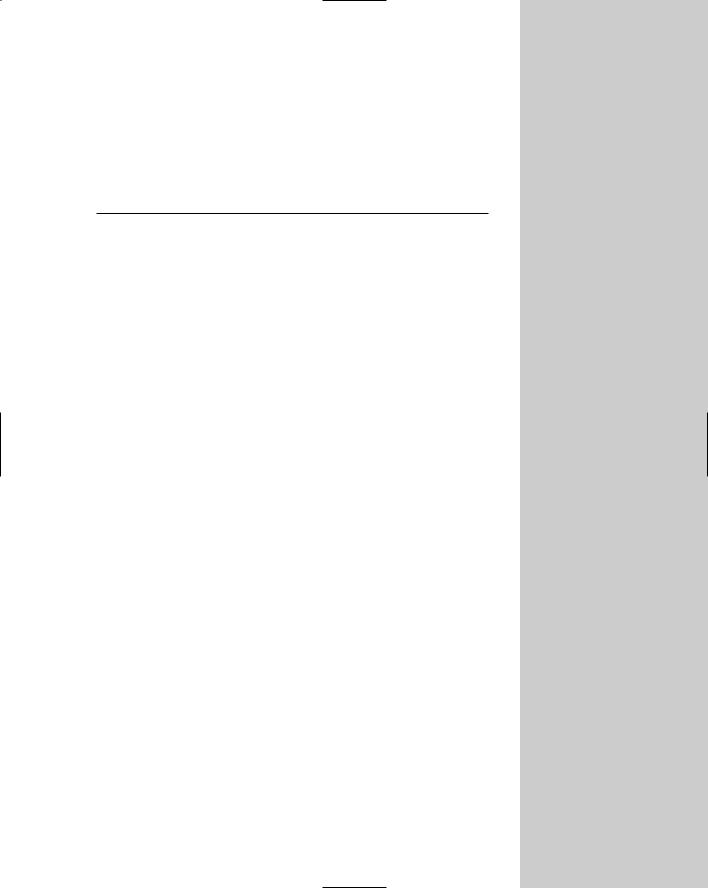
Characters can be unique, portable objects in Max. These objects are created using the Character menu commands. Characters are identified with a unique icon that is the head of the entire character hierarchy. This icon is called a node. Figure 36-1 shows the character icon. The icon itself is a simple 2D disc with a simple human figure on it.
You can control the size (radius) of the character icon with the Icon Size value in the Display rollout, but increasing the icon’s size has no effect on the character.
When a character is created, all the objects included in the character automatically become children objects of the Character node with the character icon acting as the parent object. Selecting the icon selects the parent object, and double-clicking the icon selects the entire character and all its objects.
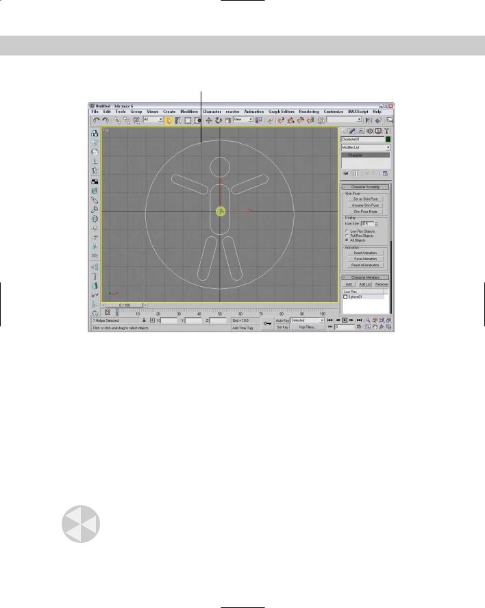
The position of the character icon also defines the starting position of the character. Moving the character icon moves the entire character. Figure 36-2 shows the Futuristic man object after it has been converted into a character. The character icon is selected and looks like a hula hoop around the character’s waist.
36C H A P T E R
In This Chapter
Saving and loading characters
Setting a skin pose
Merging animations
888 Part VIII Character Animation
Character node icon
Figure 36-1: The Character node icon sits at the head of the character hierarchy.
Saving and loading characters
After you have a character that you’re pleased with, you can save the entire character as a separate file. Characters are saved with the .CHR extension. You can use the Character Save Character menu command. The File menu commands such as Open, Save As, Merge, and Replace recognize files with the .MAX and the .CHR extensions.
You can insert saved characters into the current scene using the Character Insert Character menu command. This command opens a File dialog box where you can specify the character to insert.
Destroying characters
Hierarchies that have been made into a character assembly can be unrecognized as a character using the Character Destroy Character menu command. This command doesn’t delete the objects, but only removes the character icon and returns the objects to their default status.
Caution |
If the character objects are selected when the Destroy Character menu command is used, |
|
then the character objects also are deleted. |
Chapter 36 Animating Characters 889
Figure 36-2: This character is identified by the character icon around its waist.
Working with Characters
After you create a character or insert one into a scene, you can work with the character by adding new objects to the character, saving and inserting animation, and setting poses. You find most of these commands in the Character Assembly rollout, which appears in the Modify panel when the character icon is selected, but some are also in the Character menu.
Defining character members
While a character object is selected, all individual objects that make up the character are listed in the Character Members rollout. You use the Add and Remove buttons at the top of this rollout to add to or remove objects from the current character object.
This Character Members rollout includes a check box next to each item on the list. If this check box is checked, then the item is marked to be visible during Low Res mode. The Display section of the Character Assembly rollout includes options for displaying Low Res or Full Res objects.
Tip |
An easy way to create a low-res model is to apply the Optimize modifier to an object. This |
|
reduces the detail of the model. |
890 Part VIII Character Animation
Locking and unlocking characters
Characters that are created can also be locked. A locked character hides the character icon, making it impossible to get to the character settings. To lock a character, choose Character Lock. You can still move characters that are locked about the scene, but you cannot make any other changes to the objects in the character set.
You unlock a character with the Character Unlock command.
Setting a skin pose
When a character is created, the character icon marks the character and its object’s initial position. In addition to its initial position, you can set a skin pose. This pose defines how the character stands. The initial pose of the character is determined by the bone structure when a skin is applied.
After the pose has changed, you can save the current pose using the Character Set Skin Pose menu command. This saves the current pose so it can be immediately recalled using the Character Assume Skin Pose menu command. Both of these menu commands are also available as buttons in the Character Assembly rollout.
The Skin Pose Mode button lets you make changes to the current skin pose. Figure 36-3 shows the future man character from Chapter 35 set to a pose.
Figure 36-3: The Set and Assume Skin Pose buttons let you save and recall character poses.

Chapter 36 Animating Characters 891
Tutorial: Creating a frog character
When you begin to work with characters and inverse kinematics systems, you’ll find that models with long arms and legs are easier to practice on. So for this example, I found one of the best long-legged creatures around — a frog.
To create a frog character, follow these steps:
1.Open the Frog character.max file from the Chap 36 directory on the CD-ROM.
This file includes a frog model created by Zygote Media. The frog already has a bone system, and the skin modifier applied an IK setup for its legs.
2.Select the entire frog, including all its bones and IK chains, using the Edit Select All menu command (Ctrl+A). Then select the Character Create Character menu command. Set the Icon Size to 500.
3.In the Character Assembly rollout, click the Set as Skin Pose button. A simple dialog box appears asking you to confirm this action; click Yes.
This sets the current pose as the default for the frog character.
4.Then select and manipulate the bones to create a new pose for the frog character.
5.Click the Set Key button (or press the ' key). In the drop-down list above the Key Filters button, select Character01 and drag the Time Slider to frame 30. Click the Set Keys button (or press the K key) With the Character icon selected, drag the Time Slider back to frame 0 and click the Assume Skin Pose button and click the Set Keys button (or press the K key) to create the necessary keys.
6.Click the Select and Move button (or press the W key), and move the Character icon to the left in the Top viewport. Drag the Time Slider back to frame 30 and click the Set Keys button (or press the K key) to set a key for the frog moving forward.
7.Open the Select Objects dialog box (by pressing the H key), and select all the bones. Then select Tools Display Floater, and click the Hide Selected button to hide all the bones.
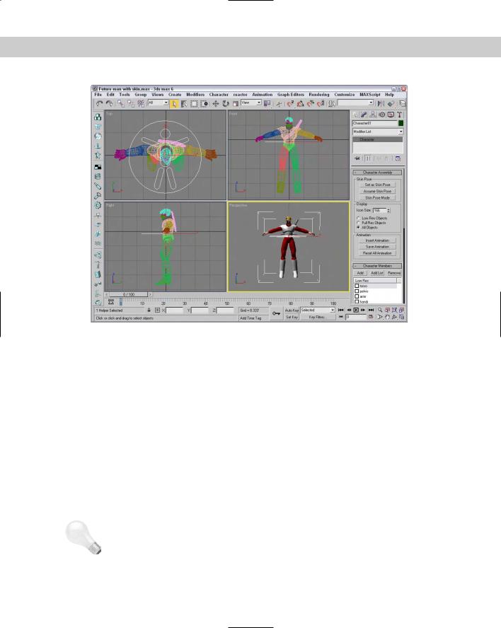
8.Click the Play Animation button (or press the / key) to see the results.
Figure 36-4 shows the frog as it jumps forward.
Saving and inserting character animations
Characters that are animated can be saved. You can insert these saved animations into a scene. You use the Save Animation button in the Animation section of the Character Assembly rollout to save an animation sequence for a character. These files are saved using the .ANM extension and include all the keys.
Animation files can also be saved as .XML files. XML is a standard mark-up language for defining actions. Although XML files take longer to process than the .ANM files, they offer a standard format that can be used by other animation tools.
892 Part VIII Character Animation
Figure 36-4: Using the character assembly and skin poses makes animating this frog easy.
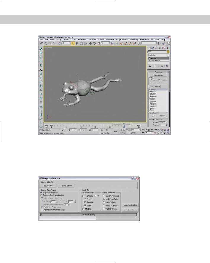
Merging animations
After you’ve saved an animated sequence for a character, you can reuse it on other characters using the File Merge Animation menu command. This command opens the Merge Animation dialog box, as shown in Figure 36-5. This dialog box includes settings for specifying the animation sequence and the destination object.
Figure 36-5: The Merge Animation dialog box lets you combine animation sequences from other characters.