


Chapter 5 Creating and Editing Primitive Objects |
171 |
Figure 5-8: The octagon, cube, tetrahedron, icosahedron, and dodecahedron objects; Plato would be amazed.
Exploring the Primitive Object Types
In the Create panel are actually two different subcategories of primitives: Standard Primitives and Extended Primitives. These primitives include a diverse range of objects from simple boxes and spheres to complex torus knots. You can create all these primitives from the Create panel.
Standard Primitives
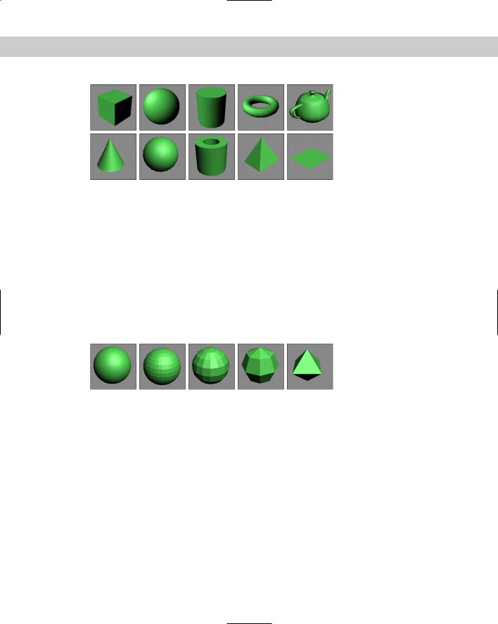
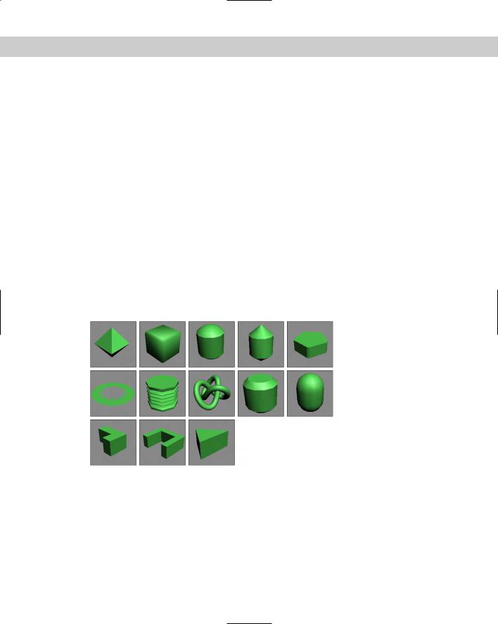
The Standard Primitives include many of the most basic and most used objects, including boxes, spheres, and cylinders. Figure 5-9 shows all the Standard Primitives.
Box
You can use the Box primitive to create regular cubes and boxes of any width, length, and height. Holding down the Ctrl key while dragging the box base creates a perfect square for the base. To create a cube, select the Cube option in the Creation Method rollout. A single click and drag completes the cube.
The Length, Width, and Height Segment values indicate how many polygons make up each dimension. The default is only one segment.
172 Part II Working with Objects
Figure 5-9: The Standard Primitives: Box, Sphere, Cylinder, Torus,
Teapot, Cone, GeoSphere, Tube, Pyramid, and Plane
Sphere
Spheres appear everywhere from sports balls to planets in space. Spheres are also among the easiest primitives to create. After clicking the Sphere button, simply click and drag in a viewport.
In the Parameters rollout, the Segments value specifies the number of polygons that make up the sphere. The higher the number of segments, the smoother the sphere is. The default value of 32 produces a smooth sphere, and a value of 4 actually produces a diamond-shaped object. The Smooth option lets you make the sphere smooth or faceted. Faceted spheres are useful for identifying faces for modifications. Figure 5-10 shows five spheres. The one on the left has 32 Segments and the Smooth option turned on. The remaining spheres have the Smooth option disabled with Segment values of 32, 16, 8, and 4.
Figure 5-10: Sphere primitives of various Segment values with the
Smooth option turned on and off
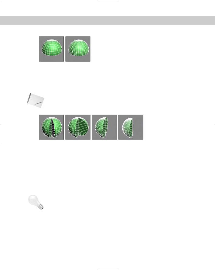
The Parameters rollout also lets you create hemispheres. The hemisphere shape is set by the Hemisphere value, which can range from 0.0 to 1.0, with 0 being a full sphere and 1 being nothing at all. (A value of 0.5 would be a perfect hemisphere.) With the Hemisphere value specified, you now have two options with which to deal with the unused polygons that make up the originating sphere: the Chop option, which removes the unused polygons, and the Squash option, which retains the polygons but “squashes” them to fit in the hemisphere shape.
Figure 5-11 shows two hemispheres with Hemisphere values of 0.5. The Edged Faces option was enabled in the Viewport Configuration dialog box so you could see the polygon faces. The left hemisphere was created using the Chop option, and the right hemisphere was created with the Squash option. Notice how many extra polygons are included in the right hemisphere.
Chapter 5 Creating and Editing Primitive Objects |
173 |
Figure 5-11: Creating hemispheres with the Chop and Squash options
The Slice option enables you to dissect the sphere into slices (like segmenting an orange). The Slice From and Slice To fields accept values ranging from 0 to 360 degrees. Figure 5-12 shows three spheres that have been sliced. Notice that, because the Segments value hasn’t changed, all slices have the same number of faces.
Note You can use the Slice feature on several primitives, including the sphere, cylinder, torus, cone, tube, oiltank, spindle, chamfercyl, and capsule.
|
Figure 5-12: Using the Slice option to create sphere slices |
|
The Base to Pivot parameter determines whether the position of the pivot point is at the bot- |
|
tom of the sphere or at the center. The default (with the Base to Pivot setting not enabled) |
|
sets the pivot point for the sphere at the center of the sphere. |
|
Cylinder |
|
You can use a cylinder in many places — for example, as a pillar in front of a home or as a car |
|
driveshaft. To create one, first specify a base circle and then a height. The default number of |
|
sides is 18, which produces a smooth cylinder. Height and Cap Segments values define the |
|
number of polygons that make up the cylinder sides and caps. The Smooth and Slice options |
|
work the same as they do with a sphere (see the preceding section). |
Tip |
If you don’t plan on modifying the ends of the cylinder, make the Cap Segments equal to 1 to |
|
keep the model complexity down. |
|
Torus |
|
A Torus (which is the mathematical name for a “doughnut”) is a ring with a circular cross sec- |
|
tion. To create a Torus, you need to specify two radii values. The first is the value from the |
|
center of the Torus to the center of the ring; the second is the radius of the circular cross |
|
section. The default settings create a Torus with 24 segments and 12 sides. The Rotation and |
|
Twist options cause the sides to twist a specified value as the ring is circumnavigated. |
174 Part II Working with Objects
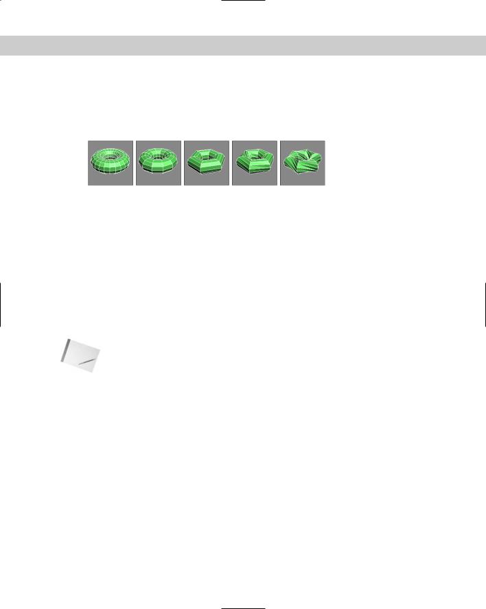
Figure 5-13 shows some sample Toruses with a Smooth setting of None. The first three have Segments values of 24, 12, and 6. The last two have Twist values of 90 and 360. The higher the number of segments, the rounder the Torus looks when viewed from above. The default of 24 is sufficient to create a smooth Torus. The number of sides defines the circular smoothness of the cross section.
Figure 5-13: Using the Segments and Twist options on a Torus
The Parameters rollout includes settings for four different Smooth options. The All option smoothes all edges, and the None option displays all polygons as faceted. The Sides option smoothes edges between sides, resulting in a Torus with banded sides. The Segment option smoothes between segment edges, resulting in separate smooth sections around the Torus.
The Slice options work with a Torus the same way as they do with the sphere and cylinder objects (see the section “Sphere” earlier in this chapter).
Teapot
Okay, let’s all sing together, “I’m a little teapot, short and stout. . . .” The teapot is another object that, like the sphere, is easy to create. Within the Parameters rollout, you can specify the number of Segments, whether the surface is smooth or faceted, and which parts to display, including Body, Handle, Spout, and Lid.
Note You may recognize most of these primitives as standard shapes, with the exception of the teapot. The teapot has a special place in computer graphics. In early computer graphics development labs, the teapot was chosen as the test model for many early algorithms. It is still included as a valuable benchmark for computer graphics programmers.
Cone
The Cone object, whether used to create ice cream cones or megaphones, is created exactly like the cylinder object except that the second cap can have a radius different from that of the first. You create it by clicking and dragging to specify the base circle, dragging to specify the cone’s height, and then dragging again for the second cap to create a Cone.
In addition to the two cap radii and the Height, parameter options include the number of Height and Cap Segments, the number of Sides, and the Smooth and Slice options.
GeoSphere
The GeoSphere object is a sphere that is created using fewer polygon faces than the standard Sphere object. This type of sphere spreads the polygon faces, which are all equal in size, around the object, instead of concentrating them on either end like the normal Sphere object. This makes the GeoSphere object easier to model while using less memory. One reason for this is that a GeoSphere uses triangle faces instead of square faces.
Chapter 5 Creating and Editing Primitive Objects |
175 |
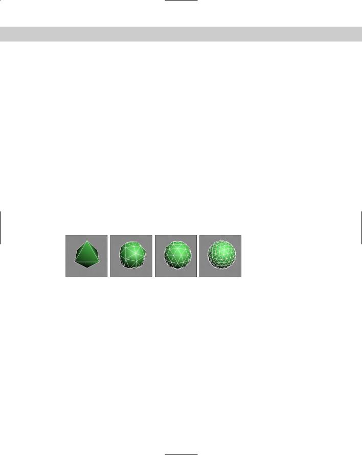
In the Parameters rollout are several Geodesic Base Type options, including Tetra, Octa, and Icosa. The Tetra type is based on a four-sided tetrahedron, the Octa type is based on an eight-sided Octahedron, and the Icosa type is based on the 20-sided Icosahedron. Setting the Segment value to 1 produces each of these Hedron shapes. Each type aligns the triangle faces differently.
GeoSpheres also have the same Smooth, Hemisphere, and Base to Pivot options as the Sphere primitive. Selecting the Hemisphere option changes the GeoSphere into a hemisphere, but you have no additional options like Chop and Squash. GeoSphere primitives do not include an option to be sliced.
Tutorial: Comparing Spheres and GeoSpheres
To prove that GeoSpheres are more efficient than Sphere objects, follow these steps:
1.Create a normal Sphere, and set its Segment value to 4.
2.Next to the Sphere object, create a GeoSphere object with a Tetra Base Type and the number of Segments set to 4.
3.Create another GeoSphere object with the Octa Base Type and 4 Segments.
4.Finally, create a GeoSphere with the Icosa Base Type and 4 Segments.
Figure 5-14 shows these spheres as a comparison. The normal sphere, shown to the left, looks like a diamond, but the GeoSpheres still resemble spheres. Notice that the Icosa type GeoSphere, shown in the lower right, produces the smoothest sphere.
Figure 5-14: Even with a similar number of segments, GeoSpheres are much more spherical.
Tube
The Tube primitive is useful for any time you need a pipe object. You can also use it to create ring-shaped objects that have rectangular cross sections. Creating a Tube object is very similar to the Cylinder and Cone objects. Tube parameters include two radii for the inner and outer tube wall. Tubes also have the Smooth and Slice options.
Pyramid
Pyramid primitives are constructed with a rectangular base and triangles at each edge that rise to meet at the top, just like they made in Egypt, only easier. Two different creation methods are used to create the base rectangle. With the Base/Apex method, you create the base by dragging corner to corner, and with the Center method, you drag from the base center to a corner.
176 Part II Working with Objects
The Width and Depth parameters define the base dimensions, and the Height value determines how tall the pyramid is. You can also specify the number of segments for each dimension.
Plane
The Plane object enables you to model the Great Plains (good pun, eh?). The Plane primitive creates a simple plane that looks like a rectangle, but it includes Multiplier parameters that let you specify the size of the plane at render time. This feature makes working in a viewport convenient because you don’t have to worry about its actual dimensions.
The Plane primitive includes two creation methods: Rectangle and Square. The Square method creates a perfect square in the viewport when dragged. You can also define the Length and Width Segments, but the real benefits of the Plane object are derived from the use of the Render Multipliers.
The Scale Multiplier value determines how many times larger the plane should be at render time. Both Length and Width are multiplied by equal values. The Density Multiplier specifies the number of segments to produce at render time.
Extended Primitives
Access the Extended Primitives by selecting Extended Primitives in the subcategory dropdown list in the Create panel. These primitives aren’t as generic as the Standard Primitives but are equally useful (see Figure 5-15).
Figure 5-15: The Extended Primitives: Hedra, ChamferBox, OilTank,
Spindle, Gengon, RingWave, Hose, Torus Knot, ChamferCyl, Capsule,
L-Ext, C-Ext, and Prism
Hedra
Hedras, or Polyhedra, form the basis for a class of geometry defined by fundamental mathematical principles. In addition to Plato, Johannes Kepler used these Polyhedra as the basis for his famous “Harmony of the Spheres” theory. The Hedra primitives (shown in the first tutorial of this chapter) available in Max are Tetrahedron, Cube/Octahedron,
Chapter 5 Creating and Editing Primitive Objects |
177 |
Dodecahedron/Icosahedron, and two Star types called Star1 and Star2. From these basic Polyhedra, you can create many different variations.
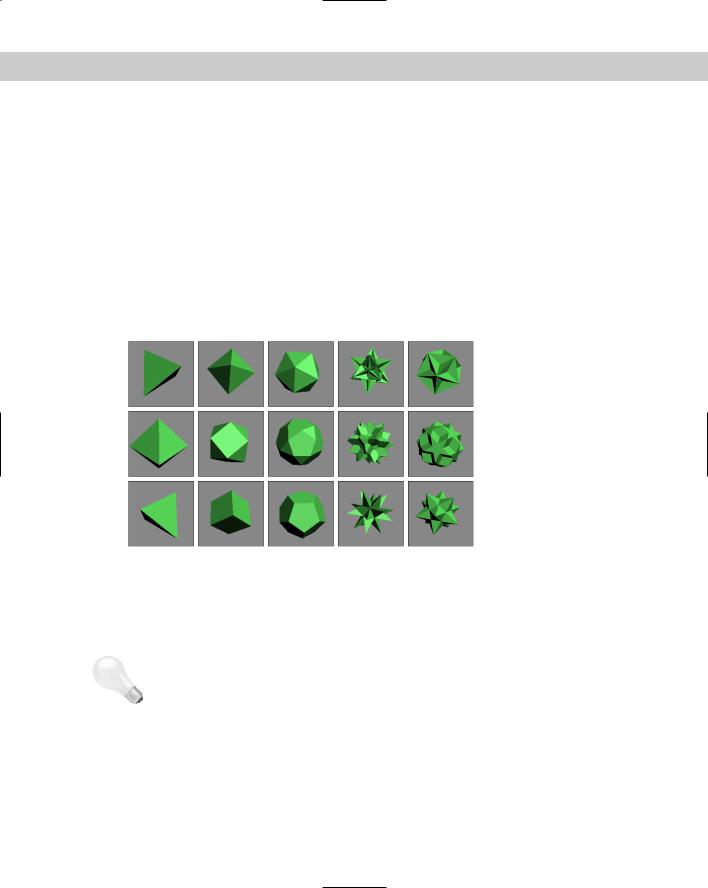
The Family section options determine the shape of the Hedra. Each member of a Hedra pair is mathematically related to the other member. The Family Parameters include P and Q values. These values change the Hedra between the two shapes that make up the pair. For example, if the family option is set to Cube/Octa, then a P value of 1 displays an Octagon, and a Q value of 1 displays a Cube. When both P and Q values are set to 0, the shape becomes an intermediate shape somewhere between a Cube and an Octagon. Because the values are interrelated, only one shape of the pair can have a value of 1 at any given time. Both P and Q cannot be set to 1 at the same time.
Figure 5-16 shows each of the basic Hedra Families in columns from left to right: Tetra, Cube/Octa, Dodec/Icos, Star1, and Star2. The top row has a P value of 1 and a Q value of 0, the middle row has both P and Q set to 0, and the bottom row sets P to 0 and Q to 1. Notice that the middle row shapes are a combination of the top and bottom rows.
|
Figure 5-16: The Hedra Families with the standard shapes in the top |
|
and bottom rows and the intermediate shapes in the middle row |
|
The relationship between P and Q can be described in this manner: When the P value is set |
|
to 1 and the Q value is set to 0, one shape of the pair is displayed. As the P value decreases, |
|
each vertex becomes a separate face. The edges of these new faces increase as the value is |
|
decreased down to 0.The same holds true for the Q value. |
Tip |
Altering the P and Q parameters can create many unique shapes. For each Hedra, try the fol- |
|
lowing combinations: P = 0, Q = 0; P = 1, Q = 0; P = 0, Q = 1; P = 0.5, Q = 0.5; P = 0.5, Q = 0; |
|
P = 0, Q = 0.5. These represent the main intermediate objects. |
|
As the geometry of the objects changes, the Hedra can have as many as three different types |
|
of polygons comprising the faces. These polygons are represented by the P, Q, and R Axis |
|
Scaling values. Each type of face can be scaled, creating sharp points extending from each |
|
face. If only one unique polygon is used for the faces, then only one Axis Scaling parameter is |
|
active. The Reset button simply returns the Axis Scaling value back to its default at 100. For |
178 Part II Working with Objects
example, using the R Axis Scaling value, pyramid shapes can be extended from each face of a cube.
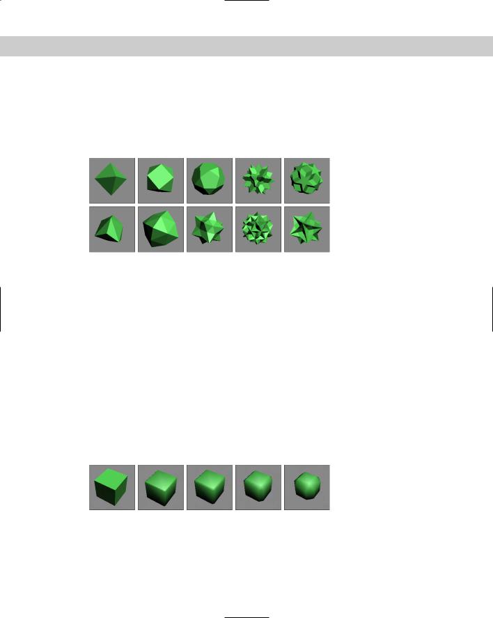
Figure 5-17 shows some results of using the Axis Scaling options. One of each family type has been created and displayed in the top row for reference. The bottom row has had an axis scaled to a value of 170. This setting causes one type of polygon face to be extended, thereby producing a new shape.
Figure 5-17: Hedras with extended faces, compliments of the Axis
Scaling option
The Vertices parameter options add more vertices and edges to the center of each extended polygon. The three options are Basic, which is the default and doesn’t add any new information to the Hedra; Center, which adds vertices to the center of each extended polygon; and Center and Sides, which add both center vertices and connecting edges for each face that is extended using the Axis Scaling options. With these options set, you can extend the polygon faces at your own discretion.
Way at the bottom of the Parameters rollout is the Radius value.
ChamferBox
A chamfered object is an object whose edges have been smoothed out, so a ChamferBox primitive is a box with beveled edges. The parameter that determines the amount of roundness applied to an edge is Fillet. In many ways, this object is just a simple extension of the Box primitive.
The only additions in the Parameters rollout are two fields for controlling the Fillet dimension and the Fillet Segments. Figure 5-18 shows a ChamferBox with Fillet values of 0, 5, 10, 20, and 30 and the Smooth option turned on.
Figure 5-18: A ChamferBox with progressively increasing Fillet values
Chapter 5 Creating and Editing Primitive Objects |
179 |
Cylindrical extended primitives
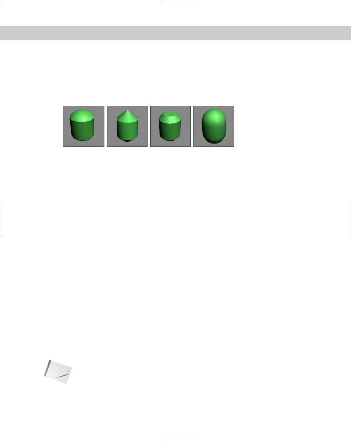
The Extended Primitives include several objects based on the Cylinder primitive that are very similar. The only real differences are the shape of the caps at either end. These four similar objects include the OilTank, Spindle, ChamferCyl, and Capsule. Figure 5-19 shows these similar objects side by side.
Figure 5-19: Several different cylindrical extended primitive objects exist, including: Oil Tank, Spindle, ChamferCyl, and Capsule.
OilTank
OilTank seems like a strange name for a primitive. This object is essentially the Cylinder primitive with dome caps like you would see on a diesel truck transporting oil. The Parameters rollout includes an additional option for specifying the Cap Height. The Height value can be set to indicate the entire height of the object with the Overall option or the height to the edge of the domes using the Centers option. The only other new option is Blend, which smoothes the edges between the cylinder and the caps. All cylindrical primitives can also be sliced just like the sphere object.
Spindle
The Spindle primitive is the same as the OilTank primitive, except that the dome caps are replaced with conical caps. All other options in the Parameters rollout are identical to the OilTank primitive.
ChamferCyl
The ChamferCyl primitive is very similar to the ChamferBox primitive, only applied to a cylinder instead of a box. The Parameters rollout includes some additional fields for handling the Fillet values.
Capsule
The Capsule primitive is a yet another primitive based on the cylinder, only this time with hemispherical caps. This object resembles the OilTank primitive very closely. The only real noticeable difference is in the border between the cylinder and caps.
Gengon
The Gengon primitive creates and extrudes regular polygons such as triangles, squares, and pentagons. There is even an option to Fillet (or smooth) the edges. To specify which polygon to use, enter a value in the Sides field.
Note |
The Gengon menu command is missing from the Create Extended Primitives menu, but |
|
you can still access it from the Create panel. |
180 Part II Working with Objects
Figure 5-20 shows five simple Gengons with different numbers of edges.
Figure 5-20: Gengon primitives are actually just extruded regular polygons.
RingWave
The RingWave primitive is a specialized primitive that you can use to create a simple gear or a sparkling sun. It consists of two circles that make up a ring. You can set the circle edges to be wavy and even fluctuate over time. You can also use RingWaves to simulate rapidly expanding gases that would result from a planetary explosion. If you’re considering a Shockwave effect, then you should look into using a RingWave primitive.
The Radius setting and the inner edge define the outer edge by the Ring Width. This ring can also have a Height. The Radial and Height Segments and the number of Sides determine the complexity of the object.
The RingWave Timing controls set the expansion values. The Start Time is the frame where the ring begins at zero, the Grow Time is the number of frames required to reach its full size, and the End Time is the frame where the RingWave object stops expanding. The No Growth option prevents the object from expanding, and it remains the same size from the Start frame to the End frame. The Grow and Stay option causes the RingWave to expand from the Start Time until the Grow Time frame is reached, and then remain full-grown until the End Time. The Cyclic Growth begins expanding the objects until the Grow Time is reached. It then starts again from zero and expands repeatedly until the End Time is reached.
The last two sections of the Parameters rollout define how the inner and outer edges look and are animated. If the Edge Breakup option is on, then the rest of the settings are enabled. These additional settings control the number of Major and Minor Cycles, the Width Flux for these cycles, and the Crawl Time, which is the number of frames to animate.
The Surface Parameters section includes an option for creating Texture Coordinates, which are the same as mapping coordinates for applying textures. There is also an option to Smooth the surface of the object.
Figure 5-21 shows five animated frames of a RingWave object with both Inner and Outer Edge Breakup settings. Notice that the edges change over the different frames.
Figure 5-21: Five frames of a rapidly expanding and turbulent RingWave object
Chapter 5 Creating and Editing Primitive Objects |
181 |
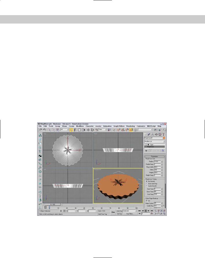
Tutorial: Creating a pie
This tutorial provides a very different recipe for creating a pie using a RingWave object. Although the RingWave object can be animated, you also can use it to create static objects such as this pie, or a set of gears.
To create a pie using the RingWave object, follow these steps:
1.Select Create Extended Primitives RingWave and drag in the Top viewport to create a RingWave object.
2.In the Parameters rollout, set the Radius to 115, the Ring Width to 90, and the Height to 30.
3.In the RingWave Timing section, select the No Growth option. Then enable the Outer Edge Breakup option, set the Major Cycles to 25, the Width Flux to 4.0, and the Minor Cycles to 0.
4.Enable the Inner Edge Breakup option. Set the Major Cycles to 6, the Width Flux to 15, and the Minor Cycles to 25 with a Width Flux of 10.
Figure 5-22 shows a nice pie object as good as Grandmother made. You can take this pie one step further by selecting Modifiers Parametric Deformers Taper to apply the Taper modifier and set the Amount to 0.1.
Figure 5-22: This pie object was created using the RingWave object.
182 Part II Working with Objects
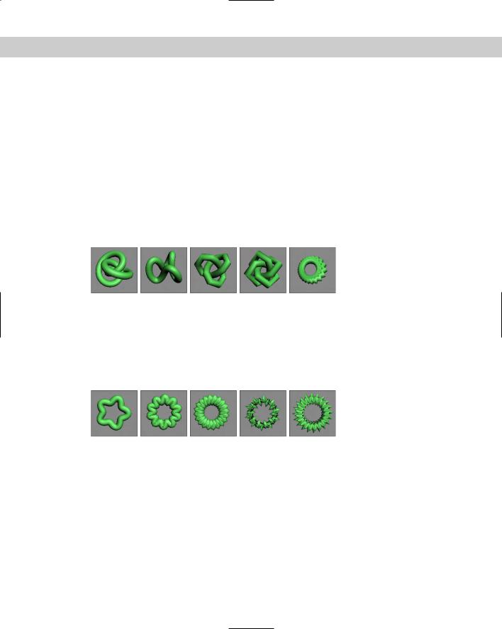
Torus Knot
A Torus Knot is similar to the Torus covered earlier, except that the circular cross-section follows a 3D curve instead of a simple circle. The method for creating the Torus Knot primitive is the same as that for creating the Torus. The Parameters rollout even lets you specify the base curve to be a circle instead of a knot. A knot is a standard, mathematically defined 3D curve.
Below the Radius and Segment parameters are the P and Q values. These values can be used to create wildly variant Torus Knots. The P value is a mathematical factor for computing how the knot winds about its vertical axis. The maximum value is 25, which makes the knot resemble a tightly wound spool. The Q value causes the knot to wind horizontally. It also has a maximum value of 25. Setting both values to the same number results in a simple circular ring.
Figure 5-23 shows some of the beautiful shapes that are possible by altering the P and Q values of a Torus Knot. These Torus Knots have these values: P = 3, Q = 2; the second has P = 1, Q = 3; the third has P = 10, Q = 15; the fourth has P = 15, Q = 20; and the fifth has P = 25, Q = 25.
Figure 5-23: Various Torus Knots display the beauty of mathematics.
When the Base Curve is set to Circle, like those in Figure 5-23, the P and Q values become disabled, and the Warp Count and Warp Height fields become active. These fields control the number of ripples in the ring and their height. Figure 5-24 shows several possibilities. From left to right, the settings are Warp Count = 5, Warp Height = 0.5; Warp Count = 10, Warp Height = 0.5; Warp Count = 20, Warp Height = 0.5; Warp Count = 50, Warp Height = 0.5; and Warp Count = 100, Warp Height = 0.75.
Figure 5-24: Torus Knots with a Circle Base Curve are useful for creating impressive rings.
In addition to the Base Curve settings, you can also control several settings for the Cross Section. The Radius and Sides values determine the size of the circular cross section and the number of segments used to create the cross section. The Eccentricity value makes the circular cross section elliptical by stretching it along one of its axes. The Twist value rotates each successive cross section relative to the previous one creating a twisting look along the object. The Lumps value sets the number of lumps that appear in the Torus Knot, and the Lump Height and Offset values set the height and starting point of these lumps.

Chapter 5 Creating and Editing Primitive Objects |
183 |
The Smooth options work just like those for the Torus object by smoothing the entire object, just the sides, or none. You can also set the U and V axis Offset and Tiling values for the mapping coordinates.
L-Ext
The L-Ext primitive stands for L-Extension. You can think of it as two rectangular boxes that are connected at right angles to each other. To create an L-Ext object, you need to first drag to create a rectangle that defines the overall area of the object. Next you drag to define the Height of the object, and, finally, you drag to define the width of each leg.
The Parameters rollout includes dimensions for Side and Front Lengths, Side and Front Widths, and the Height. You can also define the number of Segments for each dimension.
C-Ext
The C-Ext primitive is the same as the L-Ext primitive with an extra rectangular box. The C shape connects three rectangular boxes at right angles to each other.
The Parameters rollout includes dimensions for Side, Front, and Back Lengths and Widths, and the Height. You can also define the number of Segments for each dimension. These primitives are great if your name is Clive Logan or Carrie Lincoln.
Prism
The Prism primitive is essentially an extruded triangle. If you select the Base/Apex creation method, then each of the sides of the base triangle can have a different length. With this creation method, the first click in the viewport sets one edge of the base triangle, the second click sets the opposite corner of the triangle that affects the other two edges, and the final click sets the height of the object.
The other creation method is Isosceles, which doesn’t let you skew the triangle before setting the height.
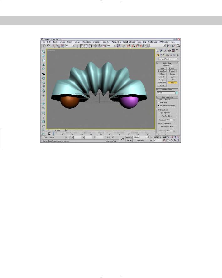
Hose
The Hose primitive is a flexible connector that can be positioned between two other objects. It acts much like a spring but has no dynamic properties. In the Hose Parameters rollout, you can specify the Hose as a Free Hose or Bound to Object Pivots. If the Free Hose option is selected, you can set the Hose Height. If the Bound to Object Pivots option is selected, then two Pick Object buttons appear for the Top and Bottom objects. Once bound to two objects, the hose stretches between the two objects when either is moved. You can also set the Tension for each bound object.
For either the Bound Hose or Free Hose, you can set the number of Segments that make up the hose; whether the flexible section is enabled; to smooth along the Sides, Segments, neither, or all; whether the hose is Renderable; and to Generate Mapping Coordinates for applying texture maps. If the flexible section is enabled, then you can set where the flexible section Starts and Ends, the number of Cycles, and its Diameter.
You can also set the Hose Shape to Round, Rectangular, or D-Section. Figure 5-25 shows a flexible hose object bound to two sphere objects.
184 Part II Working with Objects
Figure 5-25: The Hose object flexes between its two bound objects.
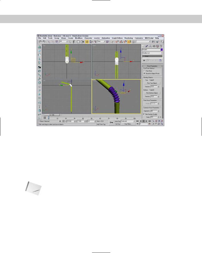
Tutorial: Creating a bendable straw
If you’ve ever found yourself modeling a juice box (or drinking from a juice box and wondering, “How would I model this bendable straw?”), then this tutorial is for you. The nice part about the Hose primitive it that once you’ve created the model, you can reposition the straw and the bend changes as needed, just like a real straw.
To create a bendable straw, follow these steps:
1.Open the Bendable straw.max file from the Chap 05 directory on the CD-ROM.
This file includes two Tube primitives to represent the top and bottom portions of a straw. I’ve oriented their pivot points so the Z-axis points toward where the Hose primitive will go.
2.Select Create Extended Primitives Hose and drag in the Top viewport close to where the two straws meet. Select the Bound to Object Pivots option, click on the Pick Top Object button, and select the top Tube object. Then click on the Pick Bottom Object button and select the bottom Tube object. This step positions the Hose object between the two Tube pieces.
3.In the Hose Parameters rollout, set the Tension for both Tubes to 10.0. Set the Segments to 40, the Starts value to 0, the Ends value to 100, the Cycles to 10, and the Diameter to 40. Make sure the Renderable option is enabled and enable the Round Hose option with a Diameter of 15.0.
Figure 5-26 shows the completed bendable straw created using a Hose primitive.
Chapter 5 Creating and Editing Primitive Objects |
185 |
Figure 5-26: Use the Hose primitive to connect two objects.
Modifying object parameters
Primitive objects provide a good starting point for many of the other modeling types. They also provide a good way to show off parameter-based modeling.
All objects have parameters. These parameters help define how the object looks. For example, consider the primitive objects. The primitive objects contained in Max are parametric. Parametric objects are mathematically defined, and you can change them by modifying their parameters. The easiest object modifications to make are simply changing these parameters. For example, a sphere with a radius of 4 can be made into a sphere with a radius of 10 by simply typing a 10 in the Radius field. The viewports display these changes automatically when you press the Enter key.
Note When an object is first created, its parameters are displayed in the Parameters rollout of the Create panel. As long as the object remains the current object, you can modify its parameters using this rollout. After you select a different tool or object, the Parameters rollout is no longer accessible from the Create panel. It can be found from then on under the Modify panel.
Tutorial: Filling a treasure chest with gems
I haven’t found many treasure chests lately, but if I remember correctly, they are normally filled with bright, sparkling gems. In this tutorial, we fill the chest with a number of Hedra primitives and alter the object properties in the Modify panel to create a diverse offering of gems.

186 Part II Working with Objects
To create a treasure chest with many unique gems, follow these steps:
1.Open the Treasure chest of gems.max file from the Chap 05 directory on the CD-ROM. This file includes a simple treasure chest model.
2.Select Create Extended Primitives Hedra to open the Extended Primitives subcategory in the Create panel and select the Hedra button.
3.Create several Hedra objects. The size of the objects doesn’t matter at this time.
4.Open the Modify panel, and select one of the Hedra objects.
5.Alter the values in the Parameters rollout to produce a nice gem.
6.Repeat Step 5 for all Hedra objects in the chest.
Figure 5-27 shows the resulting chest with a variety of gems.
Every modeling type, whether it is an Editable Spline, a Compound Conform object, or a NURBS Point curve, has parameters. These parameters, which you can modify, appear in rollouts using the Modify panel.
Figure 5-27: A treasure chest full of gems quickly created by altering object parameters