

- •Preface
- •About This Book
- •Acknowledgments
- •Contents at a Glance
- •Contents
- •Relaxing at the Beach
- •Dressing the Scene
- •Animating Motion
- •Rendering the Final Animation
- •Summary
- •The Interface Elements
- •Using the Menus
- •Using the Toolbars
- •Using the Viewports
- •Using the Command Panel
- •Using the Lower Interface Bar Controls
- •Interacting with the Interface
- •Getting Help
- •Summary
- •Understanding 3D Space
- •Using the Viewport Navigation Controls
- •Configuring the Viewports
- •Working with Viewport Backgrounds
- •Summary
- •Working with Max Scene Files
- •Setting File Preferences
- •Importing and Exporting
- •Referencing External Objects
- •Using the File Utilities
- •Accessing File Information
- •Summary
- •Customizing Modify and Utility Panel Buttons
- •Working with Custom Interfaces
- •Configuring Paths
- •Selecting System Units
- •Setting Preferences
- •Summary
- •Creating Primitive Objects
- •Exploring the Primitive Object Types
- •Summary
- •Selecting Objects
- •Setting Object Properties
- •Hiding and Freezing Objects
- •Using Layers
- •Summary
- •Cloning Objects
- •Understanding Cloning Options
- •Mirroring Objects
- •Cloning over Time
- •Spacing Cloned Objects
- •Creating Arrays of Objects
- •Summary
- •Working with Groups
- •Building Assemblies
- •Building Links between Objects
- •Displaying Links and Hierarchies
- •Working with Linked Objects
- •Summary
- •Using the Schematic View Window
- •Working with Hierarchies
- •Setting Schematic View Preferences
- •Using List Views
- •Summary
- •Working with the Transformation Tools
- •Using Pivot Points
- •Using the Align Commands
- •Using Grids
- •Using Snap Options
- •Summary
- •Exploring the Modifier Stack
- •Exploring Modifier Types
- •Summary
- •Exploring the Modeling Types
- •Working with Subobjects
- •Modeling Helpers
- •Summary
- •Drawing in 2D
- •Editing Splines
- •Using Spline Modifiers
- •Summary
- •Creating Editable Mesh and Poly Objects
- •Editing Mesh Objects
- •Editing Poly Objects
- •Using Mesh Editing Modifiers
- •Summary
- •Introducing Patch Grids
- •Editing Patches
- •Using Modifiers on Patch Objects
- •Summary
- •Creating NURBS Curves and Surfaces
- •Editing NURBS
- •Working with NURBS
- •Summary
- •Morphing Objects
- •Creating Conform Objects
- •Creating a ShapeMerge Object
- •Creating a Terrain Object
- •Using the Mesher Object
- •Working with BlobMesh Objects
- •Creating a Scatter Object
- •Creating Connect Objects
- •Modeling with Boolean Objects
- •Creating a Loft Object
- •Summary
- •Understanding the Various Particle Systems
- •Creating a Particle System
- •Using the Spray and Snow Particle Systems
- •Using the Super Spray Particle System
- •Using the Blizzard Particle System
- •Using the PArray Particle System
- •Using the PCloud Particle System
- •Using Particle System Maps
- •Controlling Particles with Particle Flow
- •Summary
- •Understanding Material Properties
- •Working with the Material Editor
- •Using the Material/Map Browser
- •Using the Material/Map Navigator
- •Summary
- •Using the Standard Material
- •Using Shading Types
- •Accessing Other Parameters
- •Using External Tools
- •Summary
- •Using Compound Materials
- •Using Raytrace Materials
- •Using the Matte/Shadow Material
- •Using the DirectX 9 Shader
- •Applying Multiple Materials
- •Material Modifiers
- •Summary
- •Understanding Maps
- •Understanding Material Map Types
- •Using the Maps Rollout
- •Using the Map Path Utility
- •Using Map Instances
- •Summary
- •Mapping Modifiers
- •Using the Unwrap UVW modifier
- •Summary
- •Working with Cameras
- •Setting Camera Parameters
- •Summary
- •Using the Camera Tracker Utility
- •Summary
- •Using Multi-Pass Cameras
- •Creating Multi-Pass Camera Effects
- •Summary
- •Understanding the Basics of Lighting
- •Getting to Know the Light Types
- •Creating and Positioning Light Objects
- •Viewing a Scene from a Light
- •Altering Light Parameters
- •Working with Photometric Lights
- •Using the Sunlight and Daylight Systems
- •Using Volume Lights
- •Summary
- •Selecting Advanced Lighting
- •Using Local Advanced Lighting Settings
- •Tutorial: Excluding objects from light tracing
- •Summary
- •Understanding Radiosity
- •Using Local and Global Advanced Lighting Settings
- •Working with Advanced Lighting Materials
- •Using Lighting Analysis
- •Summary
- •Using the Time Controls
- •Working with Keys
- •Using the Track Bar
- •Viewing and Editing Key Values
- •Using the Motion Panel
- •Using Ghosting
- •Animating Objects
- •Working with Previews
- •Wiring Parameters
- •Animation Modifiers
- •Summary
- •Understanding Controller Types
- •Assigning Controllers
- •Setting Default Controllers
- •Examining the Various Controllers
- •Summary
- •Working with Expressions in Spinners
- •Understanding the Expression Controller Interface
- •Understanding Expression Elements
- •Using Expression Controllers
- •Summary
- •Learning the Track View Interface
- •Working with Keys
- •Editing Time
- •Editing Curves
- •Filtering Tracks
- •Working with Controllers
- •Synchronizing to a Sound Track
- •Summary
- •Understanding Your Character
- •Building Bodies
- •Summary
- •Building a Bones System
- •Using the Bone Tools
- •Using the Skin Modifier
- •Summary
- •Creating Characters
- •Working with Characters
- •Using Character Animation Techniques
- •Summary
- •Forward versus Inverse Kinematics
- •Creating an Inverse Kinematics System
- •Using the Various Inverse Kinematics Methods
- •Summary
- •Creating and Binding Space Warps
- •Understanding Space Warp Types
- •Combining Particle Systems with Space Warps
- •Summary
- •Understanding Dynamics
- •Using Dynamic Objects
- •Defining Dynamic Material Properties
- •Using Dynamic Space Warps
- •Using the Dynamics Utility
- •Using the Flex Modifier
- •Summary
- •Using reactor
- •Using reactor Collections
- •Creating reactor Objects
- •Calculating and Previewing a Simulation
- •Constraining Objects
- •reactor Troubleshooting
- •Summary
- •Understanding the Max Renderers
- •Previewing with ActiveShade
- •Render Parameters
- •Rendering Preferences
- •Creating VUE Files
- •Using the Rendered Frame Window
- •Using the RAM Player
- •Reviewing the Render Types
- •Using Command-Line Rendering
- •Creating Panoramic Images
- •Getting Printer Help
- •Creating an Environment
- •Summary
- •Creating Atmospheric Effects
- •Using the Fire Effect
- •Using the Fog Effect
- •Summary
- •Using Render Elements
- •Adding Render Effects
- •Creating Lens Effects
- •Using Other Render Effects
- •Summary
- •Using Raytrace Materials
- •Using a Raytrace Map
- •Enabling mental ray
- •Summary
- •Understanding Network Rendering
- •Network Requirements
- •Setting up a Network Rendering System
- •Starting the Network Rendering System
- •Configuring the Network Manager and Servers
- •Logging Errors
- •Using the Monitor
- •Setting up Batch Rendering
- •Summary
- •Compositing with Photoshop
- •Video Editing with Premiere
- •Video Compositing with After Effects
- •Introducing Combustion
- •Using Other Compositing Solutions
- •Summary
- •Completing Post-Production with the Video Post Interface
- •Working with Sequences
- •Adding and Editing Events
- •Working with Ranges
- •Working with Lens Effects Filters
- •Summary
- •What Is MAXScript?
- •MAXScript Tools
- •Setting MAXScript Preferences
- •Types of Scripts
- •Writing Your Own MAXScripts
- •Learning the Visual MAXScript Editor Interface
- •Laying Out a Rollout
- •Summary
- •Working with Plug-Ins
- •Locating Plug-Ins
- •Summary
- •Low-Res Modeling
- •Using Channels
- •Using Vertex Colors
- •Rendering to a Texture
- •Summary
- •Max and Architecture
- •Using AEC Objects
- •Using Architectural materials
- •Summary
- •Tutorial: Creating Icy Geometry with BlobMesh
- •Tutorial: Using Caustic Photons to Create a Disco Ball
- •Summary
- •mental ray Rendering System
- •Particle Flow
- •reactor 2.0
- •Schematic View
- •BlobMesh
- •Spline and Patch Features
- •Import and Export
- •Shell Modifier
- •Vertex Paint and Channel Info
- •Architectural Primitives and Materials
- •Minor Improvements
- •Choosing an Operating System
- •Hardware Requirements
- •Installing 3ds max 6
- •Authorizing the Software
- •Setting the Display Driver
- •Updating Max
- •Moving Max to Another Computer
- •Using Keyboard Shortcuts
- •Using the Hotkey Map
- •Main Interface Shortcuts
- •Dialog Box Shortcuts
- •Miscellaneous Shortcuts
- •System Requirements
- •Using the CDs with Windows
- •What’s on the CDs
- •Troubleshooting
- •Index
938 Part IX Dynamics
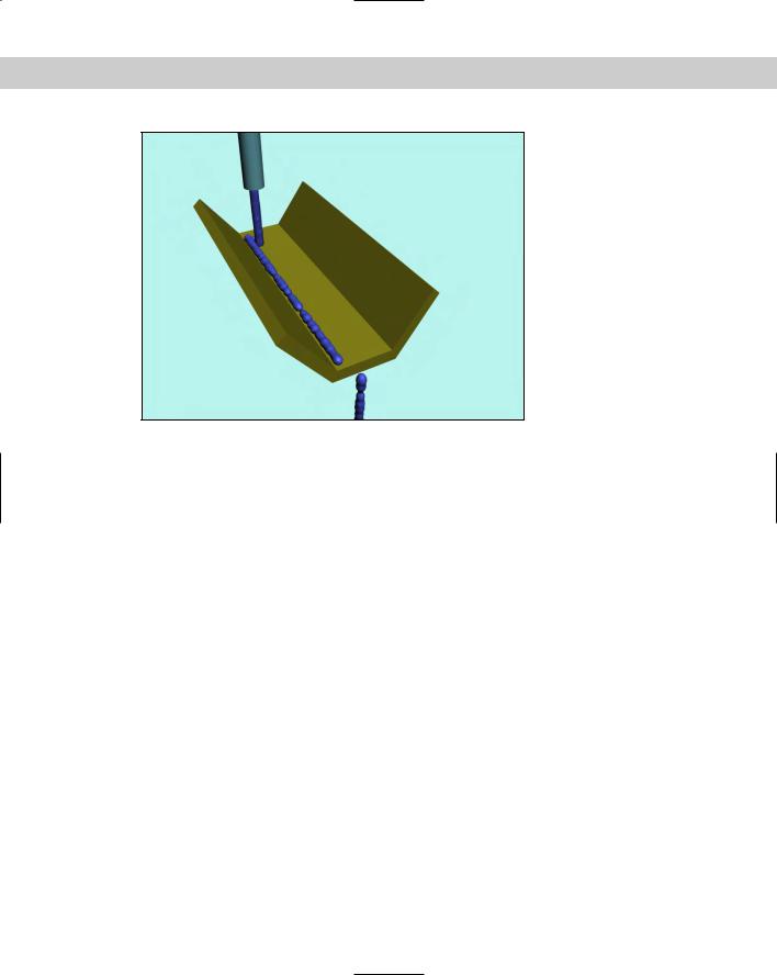
Figure 38-22: Water flowing down a trough using the Path Follow
Space Warp
Summary
Space Warps are useful for adding forces and effects to objects in the scene. Max has several different types of Space Warps, and most of them can be applied only to certain object types. In this chapter, you
Learned how to create Space Warps
Discovered how to bind Space Warps to objects
Explored in depth all the various Space Warps in several subcategories
Combined some Space Warps with particle systems to shatter glass and explode a planet
In the next chapter, we explore the ability to animate dynamic simulations.
|
|
|

Creating a Dynamic
Simulation
If something is dynamic, it moves. Dynamic objects such as the Spring and Damper objects can be animated automatically because
their positions can be computed based on certain property values.
With dynamic simulations in Max, you can animate the position and orientations of several objects in a scene automatically by setting object properties such as bounce and friction and adding forces (via Space Warps) to the scene. When you assign these properties to an object, Max can compute the effects of these properties on the motion of the object when you run the simulation.
For example, an object with a high bounce value acts like a rubber ball, and one with a lower bounce value thuds like a rock when it impacts with other objects during a dynamic simulation. Friction is a property that determines how resistant an object is to moving over another surface, such as sliding ice (lower friction) versus a sliding brick (high friction). After properties have been assigned to the objects in the simulation and Space Warps have been applied, the animation keys are determined automatically when the simulation is run.
In addition to dynamic simulations, you can use the Flex modifier to add soft-body dynamics to your scenes.
Understanding Dynamics
Dynamics is a branch of physics that deals with forces and the motions they cause, and regardless of your experience in school, physics is your friend — especially in the world of 3D. Dynamics in Max can automate the creation of animation keys by calculating the position, rotation, and collisions between objects based on physics equations.
Consider the motion of a simple yo-yo. To animate this motion with keys is fairly simple: Set rotation and position keys halfway through the animation and again at the end, and you’re done.
Now think of the forces controlling the yo-yo. Gravity causes the yo-yo to accelerate toward the ground, causing the string to unwind, which makes the yo-yo spin about its axis. When it reaches the end of the string, the rotation reverses, and the yo-yo rises. Now, using Gravity and Motor Space Warps, you can simulate this motion, but setting the keys manually is probably easier for these few objects.
39C H A P T E R
In This Chapter
Understanding the Spring and Damper dynamic objects
Defining dynamic material properties such as bounce and friction
Using Space Warps in dynamic simulations
Using the Dynamic utility
Optimizing simulation keys
Using the Flex modifier
940 Part IX Dynamics
But before you write off dynamics, think of the motion of popcorn popping. With all the pieces involved, setting all the position and rotation keys would take a long time. For this system, using dynamics makes sense.
The Dynamics utility lets you specify objects to include in a simulation, the forces they interact with, and the objects to be involved in collisions. After the system is defined, the Dynamics utility automatically calculates the movement and collisions of these objects according to the forces involved and sets the keys for you.
Object properties determine the physical characteristics of the objects. These properties are set in the Dynamics utility and in the Material Editor and include properties such as bounce, friction, density, and volume. Using these properties, you can make objects act like ice, rubber, steel, or Styrofoam.
Forces in a dynamic simulation are created using Space Warps, but not every Space Warp can be used in a dynamic simulation. You can produce additional forces using dynamic objects such as springs and dampers.
Using Dynamic Objects
In the Create Dynamics menu are two dynamic objects: Spring and Damper. These primitive objects are similar to other objects, except that you can use them in dynamic simulations.
Spring
The Spring object not only looks like a simple spring but also acts with all the forces of an actual spring. In the Spring Parameters rollout, you can choose from a Free spring or a Bound to Object Pivots spring. A free spring isn’t attached to any other objects, but the Bound to Object Pivots spring lets you select Top and Bottom objects between which the spring is stretched.
The Spring Parameters rollout also includes settings that determine the spring diameter, the number of turns, and whether it winds in a clockwise or counterclockwise direction. You can create segments automatically based on the number of turns using the Automatic Segments option or manually using the Manual Segments option. Smoothing options include All, None, Sides, and Segments. You can specify whether the spring is renderable and whether to automatically generate mapping coordinates.
The Wire Shape section lets you specify which type of cross section the spring will use. Parameters for the Round Wire option include Diameter and Sides. Parameters for the Rectangular Wire option include Width, Depth, Fillet, Fillet Segs (Segments), and Rotation. D-Section Wire is the same as the Rectangular Wire type, except that its edge corners are smoothed to form a cross section that looks like the letter D. For this type of wire, you can define the number of round sides. Figure 39-1 shows each of these spring types. On the left is the Round Wire spring type, in the middle is the Rectangular Wire spring type, and on the right is the D-Section Wire spring type.
Figure 39-1: Spring objects can have three different cross sections: Round, Rectangular, or D-Section.
Chapter 39 Creating a Dynamic Simulation 941
The Dynamics Parameters section, not shown in the previous figure, includes properties for controlling the forces that the spring applies. The Relaxed Height value is the height of the spring when no forces are applied to it. The Constant k value determines the stiffness of the spring and is a measurement of the force produced by stretching the spring. This is an actual physical constant that relates to real-world springs. The measurement unit can be pounds per inch or newtons per meter. You can also specify whether the spring works in compression only, extension only, or both. Compressing a spring means pushing the ends together, and extension means pulling the ends apart from one another.
Springs typically move in a linear fashion: When you pull on them, they return to the same location if released. Stretching a spring beyond its limits causes nonlinear motion. When you select the Enable Nonlinearity option, the spring is allowed to move in a nonlinear fashion if it is pulled too far from its relaxed state.
Damper
A damper is like a shock absorber: It is an object that absorbs force and transmits it at a lower level. A damper can also act as an actuator that causes regular forces. A damper object
includes a base and a piston with a boot inside of a housing. You can see these damper parts in Figure 39-2. Damper objects in Max are essentially massless and cannot be used in collisions.
Piston |
Boot |
Base Housing
Figure 39-2: A damper object

942 Part IX Dynamics
The Damper Parameters rollout includes two End Point Method options. The first, Free Damper/Actuator, produces the forces but isn’t bound to any objects. The second, Bound to Object Pivots, actually transmits forces to the bound objects. The Pick Piston Object and Pick Base Object buttons let you select the objects to bind to either end of the damper.
When Free Damper/Actuator is selected, the Pin-to-Pin Height spinner becomes active. This spinner lets you specify the height of the free damper. You can make dampers renderable and set them to automatically generate mapping coordinates.
In the Cylinder Parameters and Piston Parameters sections, you can set the diameters of the base, main, inside, and piston parts of the damper. You can also specify the heights of the base, main, and piston cylinders. For the main cylinder, you can fillet the top and bottom. There is also a Smooth Cylinder option for smoothing the base, main, and piston cylinders.
The Boot Parameters section enables you to create a boot within the main cylinder. The boot adds more dampening effect to the damper. In shock absorbers, the boot consists of a rubber cylinder with several folds; a similarly shaped part is found in the dynamic damper object.
The Boot Parameters section holds values for defining this part, including Minimum and Maximum Diameter, the number of Folds, and Stop Diameter and Thickness. The Stop is the end of the boot object, and the Setback value is the distance between the Stop and the end of the main cylinder. There is also an option for a Smooth Boot.
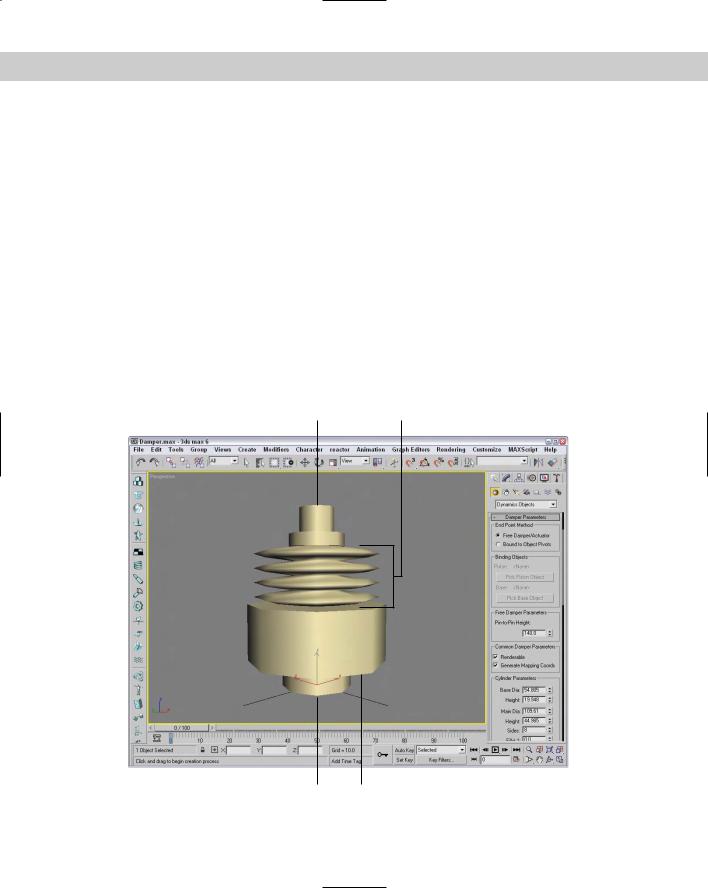
In the Dynamics Parameters section, shown in Figure 39-3, you can specify whether the object is a damper or an actuator. These options are opposite from one another. A damper absorbs force, and an actuator produces force. The Drag value is the measure of how much force the damper absorbs. It can be measured in pounds per in/sec or newtons per m/sec. Dampers can also be set to work in compression only (when end objects are pushed toward each other), extension only (when the end objects are pulled apart), or both. For an actuator, you can specify the force that it applies in pounds or newtons.
Figure 39-3: The Dynamics Parameters section of the Damper Parameters rollout defines the physical characteristics of the damper object.