

- •Preface
- •About This Book
- •Acknowledgments
- •Contents at a Glance
- •Contents
- •Relaxing at the Beach
- •Dressing the Scene
- •Animating Motion
- •Rendering the Final Animation
- •Summary
- •The Interface Elements
- •Using the Menus
- •Using the Toolbars
- •Using the Viewports
- •Using the Command Panel
- •Using the Lower Interface Bar Controls
- •Interacting with the Interface
- •Getting Help
- •Summary
- •Understanding 3D Space
- •Using the Viewport Navigation Controls
- •Configuring the Viewports
- •Working with Viewport Backgrounds
- •Summary
- •Working with Max Scene Files
- •Setting File Preferences
- •Importing and Exporting
- •Referencing External Objects
- •Using the File Utilities
- •Accessing File Information
- •Summary
- •Customizing Modify and Utility Panel Buttons
- •Working with Custom Interfaces
- •Configuring Paths
- •Selecting System Units
- •Setting Preferences
- •Summary
- •Creating Primitive Objects
- •Exploring the Primitive Object Types
- •Summary
- •Selecting Objects
- •Setting Object Properties
- •Hiding and Freezing Objects
- •Using Layers
- •Summary
- •Cloning Objects
- •Understanding Cloning Options
- •Mirroring Objects
- •Cloning over Time
- •Spacing Cloned Objects
- •Creating Arrays of Objects
- •Summary
- •Working with Groups
- •Building Assemblies
- •Building Links between Objects
- •Displaying Links and Hierarchies
- •Working with Linked Objects
- •Summary
- •Using the Schematic View Window
- •Working with Hierarchies
- •Setting Schematic View Preferences
- •Using List Views
- •Summary
- •Working with the Transformation Tools
- •Using Pivot Points
- •Using the Align Commands
- •Using Grids
- •Using Snap Options
- •Summary
- •Exploring the Modifier Stack
- •Exploring Modifier Types
- •Summary
- •Exploring the Modeling Types
- •Working with Subobjects
- •Modeling Helpers
- •Summary
- •Drawing in 2D
- •Editing Splines
- •Using Spline Modifiers
- •Summary
- •Creating Editable Mesh and Poly Objects
- •Editing Mesh Objects
- •Editing Poly Objects
- •Using Mesh Editing Modifiers
- •Summary
- •Introducing Patch Grids
- •Editing Patches
- •Using Modifiers on Patch Objects
- •Summary
- •Creating NURBS Curves and Surfaces
- •Editing NURBS
- •Working with NURBS
- •Summary
- •Morphing Objects
- •Creating Conform Objects
- •Creating a ShapeMerge Object
- •Creating a Terrain Object
- •Using the Mesher Object
- •Working with BlobMesh Objects
- •Creating a Scatter Object
- •Creating Connect Objects
- •Modeling with Boolean Objects
- •Creating a Loft Object
- •Summary
- •Understanding the Various Particle Systems
- •Creating a Particle System
- •Using the Spray and Snow Particle Systems
- •Using the Super Spray Particle System
- •Using the Blizzard Particle System
- •Using the PArray Particle System
- •Using the PCloud Particle System
- •Using Particle System Maps
- •Controlling Particles with Particle Flow
- •Summary
- •Understanding Material Properties
- •Working with the Material Editor
- •Using the Material/Map Browser
- •Using the Material/Map Navigator
- •Summary
- •Using the Standard Material
- •Using Shading Types
- •Accessing Other Parameters
- •Using External Tools
- •Summary
- •Using Compound Materials
- •Using Raytrace Materials
- •Using the Matte/Shadow Material
- •Using the DirectX 9 Shader
- •Applying Multiple Materials
- •Material Modifiers
- •Summary
- •Understanding Maps
- •Understanding Material Map Types
- •Using the Maps Rollout
- •Using the Map Path Utility
- •Using Map Instances
- •Summary
- •Mapping Modifiers
- •Using the Unwrap UVW modifier
- •Summary
- •Working with Cameras
- •Setting Camera Parameters
- •Summary
- •Using the Camera Tracker Utility
- •Summary
- •Using Multi-Pass Cameras
- •Creating Multi-Pass Camera Effects
- •Summary
- •Understanding the Basics of Lighting
- •Getting to Know the Light Types
- •Creating and Positioning Light Objects
- •Viewing a Scene from a Light
- •Altering Light Parameters
- •Working with Photometric Lights
- •Using the Sunlight and Daylight Systems
- •Using Volume Lights
- •Summary
- •Selecting Advanced Lighting
- •Using Local Advanced Lighting Settings
- •Tutorial: Excluding objects from light tracing
- •Summary
- •Understanding Radiosity
- •Using Local and Global Advanced Lighting Settings
- •Working with Advanced Lighting Materials
- •Using Lighting Analysis
- •Summary
- •Using the Time Controls
- •Working with Keys
- •Using the Track Bar
- •Viewing and Editing Key Values
- •Using the Motion Panel
- •Using Ghosting
- •Animating Objects
- •Working with Previews
- •Wiring Parameters
- •Animation Modifiers
- •Summary
- •Understanding Controller Types
- •Assigning Controllers
- •Setting Default Controllers
- •Examining the Various Controllers
- •Summary
- •Working with Expressions in Spinners
- •Understanding the Expression Controller Interface
- •Understanding Expression Elements
- •Using Expression Controllers
- •Summary
- •Learning the Track View Interface
- •Working with Keys
- •Editing Time
- •Editing Curves
- •Filtering Tracks
- •Working with Controllers
- •Synchronizing to a Sound Track
- •Summary
- •Understanding Your Character
- •Building Bodies
- •Summary
- •Building a Bones System
- •Using the Bone Tools
- •Using the Skin Modifier
- •Summary
- •Creating Characters
- •Working with Characters
- •Using Character Animation Techniques
- •Summary
- •Forward versus Inverse Kinematics
- •Creating an Inverse Kinematics System
- •Using the Various Inverse Kinematics Methods
- •Summary
- •Creating and Binding Space Warps
- •Understanding Space Warp Types
- •Combining Particle Systems with Space Warps
- •Summary
- •Understanding Dynamics
- •Using Dynamic Objects
- •Defining Dynamic Material Properties
- •Using Dynamic Space Warps
- •Using the Dynamics Utility
- •Using the Flex Modifier
- •Summary
- •Using reactor
- •Using reactor Collections
- •Creating reactor Objects
- •Calculating and Previewing a Simulation
- •Constraining Objects
- •reactor Troubleshooting
- •Summary
- •Understanding the Max Renderers
- •Previewing with ActiveShade
- •Render Parameters
- •Rendering Preferences
- •Creating VUE Files
- •Using the Rendered Frame Window
- •Using the RAM Player
- •Reviewing the Render Types
- •Using Command-Line Rendering
- •Creating Panoramic Images
- •Getting Printer Help
- •Creating an Environment
- •Summary
- •Creating Atmospheric Effects
- •Using the Fire Effect
- •Using the Fog Effect
- •Summary
- •Using Render Elements
- •Adding Render Effects
- •Creating Lens Effects
- •Using Other Render Effects
- •Summary
- •Using Raytrace Materials
- •Using a Raytrace Map
- •Enabling mental ray
- •Summary
- •Understanding Network Rendering
- •Network Requirements
- •Setting up a Network Rendering System
- •Starting the Network Rendering System
- •Configuring the Network Manager and Servers
- •Logging Errors
- •Using the Monitor
- •Setting up Batch Rendering
- •Summary
- •Compositing with Photoshop
- •Video Editing with Premiere
- •Video Compositing with After Effects
- •Introducing Combustion
- •Using Other Compositing Solutions
- •Summary
- •Completing Post-Production with the Video Post Interface
- •Working with Sequences
- •Adding and Editing Events
- •Working with Ranges
- •Working with Lens Effects Filters
- •Summary
- •What Is MAXScript?
- •MAXScript Tools
- •Setting MAXScript Preferences
- •Types of Scripts
- •Writing Your Own MAXScripts
- •Learning the Visual MAXScript Editor Interface
- •Laying Out a Rollout
- •Summary
- •Working with Plug-Ins
- •Locating Plug-Ins
- •Summary
- •Low-Res Modeling
- •Using Channels
- •Using Vertex Colors
- •Rendering to a Texture
- •Summary
- •Max and Architecture
- •Using AEC Objects
- •Using Architectural materials
- •Summary
- •Tutorial: Creating Icy Geometry with BlobMesh
- •Tutorial: Using Caustic Photons to Create a Disco Ball
- •Summary
- •mental ray Rendering System
- •Particle Flow
- •reactor 2.0
- •Schematic View
- •BlobMesh
- •Spline and Patch Features
- •Import and Export
- •Shell Modifier
- •Vertex Paint and Channel Info
- •Architectural Primitives and Materials
- •Minor Improvements
- •Choosing an Operating System
- •Hardware Requirements
- •Installing 3ds max 6
- •Authorizing the Software
- •Setting the Display Driver
- •Updating Max
- •Moving Max to Another Computer
- •Using Keyboard Shortcuts
- •Using the Hotkey Map
- •Main Interface Shortcuts
- •Dialog Box Shortcuts
- •Miscellaneous Shortcuts
- •System Requirements
- •Using the CDs with Windows
- •What’s on the CDs
- •Troubleshooting
- •Index
Chapter 19 Exploring the Material Editor 565
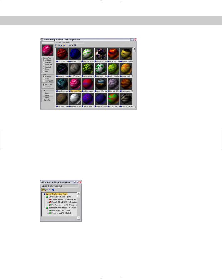
Figure 19-10: The Material/Map Browser also lets you work with saved custom material libraries.
Using the Material/Map Navigator
Each material can consist of several submaterials. For example, anytime a map is added to a material, it becomes a submaterial. A single material can consist of many submaterials, which may be maps or materials. You can edit each submaterial by accessing the rollouts associated with it. The trick is being able to locate the various submaterials. This is where the Material/Map Navigator comes in handy.
The Material/Map Navigator, shown in Figure 19-11, shows all the submaterials that make up a material in a hierarchy list. Double-clicking a submaterial opens the submaterial and all of its associated rollouts in the Material Editor.
Figure 19-11: The Material/Map Navigator shows the layered material as a hierarchy.
The Material/Map Navigator, like the Material/Map Browser, offers several viewing methods for the submaterials, including View List, View List + Icons, View Small Icons, and View Large Icons.
566 Part IV Materials and Maps
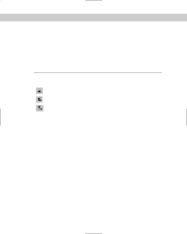
When you select a submaterial, its object type is displayed on the Object Type button. Directly above this button are three buttons that become active when you select a submaterial. These buttons, shown in Table 19-4, enable you to navigate the submaterial hierarchy. The rightmost button is Go Forward to Sibling. This moves to the next adjacent submaterial on the same level. The Go to Parent button (the second from the right) selects the submaterial’s parent. The Show End Result button is a toggle button that shows the selected submaterial or the resulting material with all submaterials included. These options are also available from the Navigation menu. The keyboard shortcuts for these buttons are the arrow keys — Up arrow for Go to Parent, Right arrow for Go Forward to Sibling, and Left arrow for Go Backward to Sibling.
|
|
Table 19-4: Submaterial Navigation Buttons |
|
|
|
|
Button |
Description |
|
|
|
|
|
Go Forward to Sibling |
|
|
Go to Parent |
|
|
Show End Result |
|
|
|
If the submaterial is itself a material, such as one of the submaterials for the Multi/Sub-object material, then you can separate the submaterial from the base material using the Make Unique button.
Summary
Materials can add much to the realism of your models. Learning to use the Material Editor, the Material/Map Browser, and the Material/Map Navigator enables you to work with materials. In this chapter, you’ve
Learned about various material properties
Worked with the Material Editor buttons and sample slots
Used the Material/Map Browser and material libraries
Used the Material/Map Navigator to view submaterials
The next chapter delves more into the topic of material, including all the simple material types.
|
|
|

Creating Simple
Materials
Now that you’ve learned the basic material properties, acquainted yourself with the Material Editor, and learned how
to apply materials to objects in the scene, this chapter gives you a chance to create some simple original materials. The simplest material is based on the Standard material type, which is the default material type. Several external tools can be very helpful when you create materials. These tools include an image-editing package such as Photoshop, a digital camera, and a scanner. With these tools, you can create and capture bitmap images that can be applied as materials to the surface of the object.
Using the Standard Material
Standard materials are the default Max material type. They provide a single, uniform color determined by the Ambient, Diffuse, Specular, and Filter color swatches. Standard materials can use any one of several different shaders. Shaders are algorithms used to compute how the material should look, given its parameters.
Standard materials also have parameters for controlling highlights, opacity, and self-illumination. Standard materials include the following rollouts: Shader Basic Parameters, Basic Parameters (based on the shader type), Extended Parameters, SuperSampling, Maps, Dynamic Properties, and mental ray connection. By modifying these parameters, you can create really unique materials. With all the various rollouts, even a standard material has an infinite number of possibilities.
Using Shading Types
Max includes several different shader types. These shaders are all available in a drop-down list in the Shader Basic Parameters rollout. Each shader type displays different options in its respective Basic Parameters rollout. Figure 20-1 shows the basic parameters for the Blinn shader. Other available shaders include Anisotropic, Metal, Multi-Layer, Oren-Nayar-Blinn, Phong, Strauss, and Translucent Shader.
20C H A P T E R
In This Chapter
Using standard materials
Learn the various shaders
Exploring the Material rollouts
Creating textures with
Photoshop
568 Part IV Materials and Maps
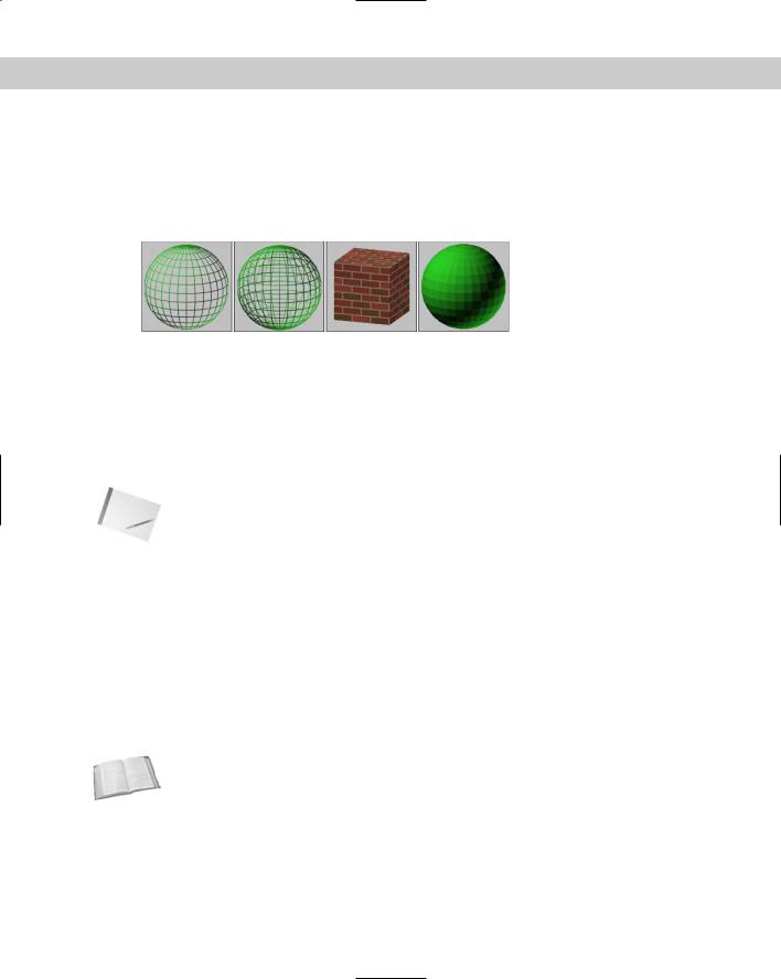
The Shader Basic Parameters rollout also includes several options for shading the material, including Wire, 2-Sided, Face Map, and Faceted, as shown in Figure 20-1. Wire mode causes the model to appear as a wireframe model. The 2-Sided option makes the material appear on both sides of the face and is typically used in conjunction with the Wire option or with transparent materials. The Face Map mode applies maps to each single face on the object. Faceted ignores the smoothing between faces.
Figure 20-1: Basic parameter options include (from left to right)
Wire, 2-Sided, Face Map, and Faceted.
Blinn shader
This shader is the default. It renders simple circular highlights and smoothes adjacent faces.
The Blinn shader includes color swatches for setting Ambient, Diffuse, Specular, and SelfIllumination colors. To change the color, click the color swatch and select a new color in the Color Selector dialog box.
Note You can drag colors among the various color swatches. When you do so, the Copy or Swap Colors dialog box appears that enables you to copy or swap the colors.
You can use the Lock buttons to the left of the color swatches to lock the colors together so that a change to one automatically changes the other. You can lock Ambient to Diffuse, and Diffuse to Specular.
The small square buttons to the right of the Ambient, Diffuse, Specular, Self-Illumination, Opacity, Specular Level, and Glossiness controls are shortcut buttons for adding a map in place of the respective parameter. Clicking these buttons opens the Material/Map Browser where you can select the map type. You can also lock the Ambient and Diffuse maps together with the lock icon to the right of the map buttons.
When a map is loaded and active, it appears in the Maps rollout and an uppercase letter M appears on its button. When a map is loaded but inactive, a lowercase m appears. After you apply a map, these buttons open to make the map the active level and display its parameters in the rollouts. Figure 20-2 shows these map buttons.
Cross- |
For more on Maps and the various map types, see in Chapter 22, “Adding Material Details |
Reference |
with Maps.” |
|
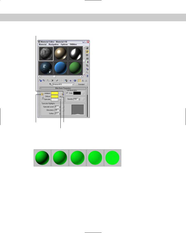
Self-Illumination can use a color if the Color option is enabled. If this option is disabled, a spinner appears that enables you to adjust the amount of default color used for illumination. Materials with a Self-Illumination value of 100 or a bright color like white lose all shadows and highlights and appear to glow from within. To remove the effect of Self-Illumination, set the spinner to 0 or the color to black. Figure 20-3 shows a sphere with Self-Illumination values (from left to right) of 0, 25, 50, 75, and 100.
Chapter 20 Creating Simple Materials 569
Locked maps icon
Locked colors |
Active map |
Inactive map
Figure 20-2: The Blinn Basic Parameters rollout lets you select and control properties for the Blinn shader.
Figure 20-3: Increasing the Self-Illumination value reduces the shadows in an object.
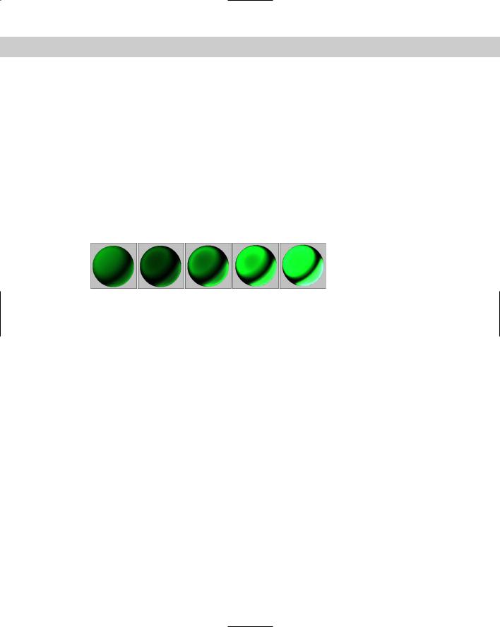
The Opacity spinner sets the level of transparency of an object. A value of 100 makes a material completely opaque, while a value of 0 makes the material completely transparent. Use the Background button to enable a patterned background image to make it easier to view the effects of the Opacity setting. Figure 20-4 shows materials with Opacity values of 10, 25, 50, 75, and 90.
570 Part IV Materials and Maps
Figure 20-4: The Opacity value sets how transparent a material is.
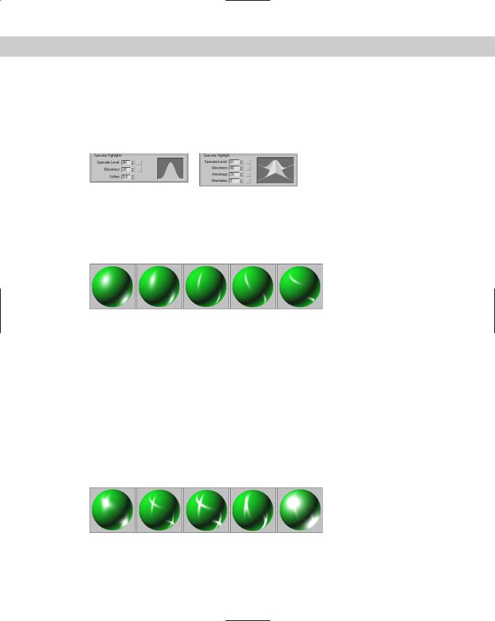
Specular Highlights are the bright points on the surface where the light is reflected at a maximum value. The Specular Level value determines how bright the highlight is. Its values can range from 0, where there is no highlight, to 100, where the highlight is at a maximum. The graph to the right of the values displays the intensity per distance for a cross section of the highlight. The Specular Level defines the height of the curve or the value at the center of the highlight where it is the brightest. This value can be overloaded to accept numbers greater than 100. Overloaded values create a larger, wider highlight.
The Glossiness value determines the size of the highlight. A value of 100 produces a pinpoint highlight, and a value of 0 increases the highlight to the edges of the graph. The Soften value doesn’t affect the graph, but it spreads the highlight across the area defined by the Glossiness value. It can range between 0 (wider) to 1 (thinner). Figure 20-5 shows a sampling of materials with Specular Highlights. The left image has a Specular Level of 20 and a Glossiness of 10, the second image has the Specular Level increased to 80, the third image has the Specular Level overloaded with a value of 150, and the last two images have the Glossiness value increased to 50 and 80, respectively.
Figure 20-5: Control Specular Highlights by altering brightness and size.
Phong shader
The Phong shader creates smooth surfaces like Blinn without the quality highlights, but it renders more quickly than the Blinn shader does. The parameters for the Phong shader are identical to those for the Blinn shader. The differences between Blinn and Phong are very subtle, but Blinn can produce highlights for lights at low angles to the surface, and its highlights are generally softer.
Anisotropic shader
The Anisotropic shader is characterized by non-circular highlights. The Anisotropy value is the difference between the two axes that make up the highlight. A value of 0 is circular, but higher values increase the difference between the axes, and the highlights are more elliptical.
Most of the parameters for this shader are the same as those for the Blinn shader, but several parameters of the Anisotropic type are unique. The Diffuse Level value determines how bright the Diffuse color appears. This is similar to Self-Illumination, but it doesn’t affect the specular highlights or the shadows. Values can range from 0 to 400.
Chapter 20 Creating Simple Materials 571
Compared with the Blinn shader, the specular highlight graph looks very different. That is because it displays two highlight components that intersect at the middle. The Specular Level value still controls the height of the curve, and the Glossiness still controls the width, but the Anisotropy value changes the width of one axis relative to the other, creating elliptical highlights. The Orientation value rotates the highlight. Figure 20-6 compares the specular highlight graphs for the Blinn and Anisotropic shaders.
Figure 20-6: The Specular highlight graph for the Blinn and
Anisotropic shaders.
Figure 20-7 shows several materials with the Anisotropic shader applied. The first three images have Anisotropic values of 30, 60, and 90, and the last two images have Orientation values of 30 and 60.
Figure 20-7: Materials with the Anisotropic shader applied have elliptical highlights.
Multi-Layer shader
The Multi-Layer shader includes two Anisotropic highlights. Each of these highlights can have a different color. All parameters for this shader are the same as the Anisotropic shader described previously, except that there are two Specular Layers and one additional parameter: Roughness. The Roughness parameter defines how well the Diffuse color blends into the Ambient color. When Roughness is set to a value of 0, an object appears the same as with the Blinn shader, but with higher values, up to 100, the material grows darker.
Figure 20-8 shows several materials with a Multi-Layer shader applied. The first two images have two specular highlights each with an Orientation value of 60 and Anisotropy values of 60 and 90. The third image has an increased Specular Level of 110 and a decrease in the
Glossiness to 10. The fourth image has a change in the Orientation value for one of the highlights to 20, and the final image has a drop in the Anisotrophy value to 10.
Figure 20-8: Materials with a Multi-Layer shader applied can have two crossing highlights.
572 Part IV Materials and Maps
Oren-Nayar-Blinn shader
The Oren-Nayar-Blinn shader is useful for creating materials for matte surfaces such as cloth and fabric. The parameters are identical to the Blinn shader, with the addition of the Diffuse Level and Roughness values.
Metal shader
The Metal shader simulates the luster of metallic surfaces. The Highlight curve has a shape that is different from that of the other shaders. It is rounder at the top and doesn’t include a Soften value. It can also accept a much higher Specular Level value (up to 999) than the other shaders. You also cannot specify a Specular color. All other parameters are similar to those of the Blinn shader. Figure 20-9 shows the several materials with the Metal shader applied. These materials differ in Specular Level values, which are (from left to right) 50, 100, 200, 400, 800.
Figure 20-9: A material with a Metal shader applied generates its own highlights.
Strauss shader
The Strauss shader provides another alternative for creating metal materials. This shader has only four parameters: Color, Glossiness, Metalness, and Opacity. The Glossiness controls the entire highlight shape. The Metalness value makes the material appear more metal-like by affecting the primary and secondary highlights. Both of these values can range between 0 and 100.
Translucent shader
The Translucent shader allows light to easily pass through an object. It is intended to be used on thin, flat plane objects, such as a bed sheet used for displaying shadow puppets. Most of the settings for this shader are the same as the others, except that it includes a Translucent color. This color is the color that the light becomes as it passes through an object with this material applied. This shader also includes a Filter color and an option for disabling the specular highlights on the backside of the object.
Tutorial: Making curtains translucent
The translucent shader can be used to create an interesting effect. Not only does light shine through an object with this shader applied, but also shadows are visible.
To make window curtains translucent, follow these steps:
1.Open the Translucent curtains.max file from the Chap 20 directory on the CD-ROM. This file contains a simple scene of a tree positioned outside a window.