

- •Preface
- •About This Book
- •Acknowledgments
- •Contents at a Glance
- •Contents
- •Relaxing at the Beach
- •Dressing the Scene
- •Animating Motion
- •Rendering the Final Animation
- •Summary
- •The Interface Elements
- •Using the Menus
- •Using the Toolbars
- •Using the Viewports
- •Using the Command Panel
- •Using the Lower Interface Bar Controls
- •Interacting with the Interface
- •Getting Help
- •Summary
- •Understanding 3D Space
- •Using the Viewport Navigation Controls
- •Configuring the Viewports
- •Working with Viewport Backgrounds
- •Summary
- •Working with Max Scene Files
- •Setting File Preferences
- •Importing and Exporting
- •Referencing External Objects
- •Using the File Utilities
- •Accessing File Information
- •Summary
- •Customizing Modify and Utility Panel Buttons
- •Working with Custom Interfaces
- •Configuring Paths
- •Selecting System Units
- •Setting Preferences
- •Summary
- •Creating Primitive Objects
- •Exploring the Primitive Object Types
- •Summary
- •Selecting Objects
- •Setting Object Properties
- •Hiding and Freezing Objects
- •Using Layers
- •Summary
- •Cloning Objects
- •Understanding Cloning Options
- •Mirroring Objects
- •Cloning over Time
- •Spacing Cloned Objects
- •Creating Arrays of Objects
- •Summary
- •Working with Groups
- •Building Assemblies
- •Building Links between Objects
- •Displaying Links and Hierarchies
- •Working with Linked Objects
- •Summary
- •Using the Schematic View Window
- •Working with Hierarchies
- •Setting Schematic View Preferences
- •Using List Views
- •Summary
- •Working with the Transformation Tools
- •Using Pivot Points
- •Using the Align Commands
- •Using Grids
- •Using Snap Options
- •Summary
- •Exploring the Modifier Stack
- •Exploring Modifier Types
- •Summary
- •Exploring the Modeling Types
- •Working with Subobjects
- •Modeling Helpers
- •Summary
- •Drawing in 2D
- •Editing Splines
- •Using Spline Modifiers
- •Summary
- •Creating Editable Mesh and Poly Objects
- •Editing Mesh Objects
- •Editing Poly Objects
- •Using Mesh Editing Modifiers
- •Summary
- •Introducing Patch Grids
- •Editing Patches
- •Using Modifiers on Patch Objects
- •Summary
- •Creating NURBS Curves and Surfaces
- •Editing NURBS
- •Working with NURBS
- •Summary
- •Morphing Objects
- •Creating Conform Objects
- •Creating a ShapeMerge Object
- •Creating a Terrain Object
- •Using the Mesher Object
- •Working with BlobMesh Objects
- •Creating a Scatter Object
- •Creating Connect Objects
- •Modeling with Boolean Objects
- •Creating a Loft Object
- •Summary
- •Understanding the Various Particle Systems
- •Creating a Particle System
- •Using the Spray and Snow Particle Systems
- •Using the Super Spray Particle System
- •Using the Blizzard Particle System
- •Using the PArray Particle System
- •Using the PCloud Particle System
- •Using Particle System Maps
- •Controlling Particles with Particle Flow
- •Summary
- •Understanding Material Properties
- •Working with the Material Editor
- •Using the Material/Map Browser
- •Using the Material/Map Navigator
- •Summary
- •Using the Standard Material
- •Using Shading Types
- •Accessing Other Parameters
- •Using External Tools
- •Summary
- •Using Compound Materials
- •Using Raytrace Materials
- •Using the Matte/Shadow Material
- •Using the DirectX 9 Shader
- •Applying Multiple Materials
- •Material Modifiers
- •Summary
- •Understanding Maps
- •Understanding Material Map Types
- •Using the Maps Rollout
- •Using the Map Path Utility
- •Using Map Instances
- •Summary
- •Mapping Modifiers
- •Using the Unwrap UVW modifier
- •Summary
- •Working with Cameras
- •Setting Camera Parameters
- •Summary
- •Using the Camera Tracker Utility
- •Summary
- •Using Multi-Pass Cameras
- •Creating Multi-Pass Camera Effects
- •Summary
- •Understanding the Basics of Lighting
- •Getting to Know the Light Types
- •Creating and Positioning Light Objects
- •Viewing a Scene from a Light
- •Altering Light Parameters
- •Working with Photometric Lights
- •Using the Sunlight and Daylight Systems
- •Using Volume Lights
- •Summary
- •Selecting Advanced Lighting
- •Using Local Advanced Lighting Settings
- •Tutorial: Excluding objects from light tracing
- •Summary
- •Understanding Radiosity
- •Using Local and Global Advanced Lighting Settings
- •Working with Advanced Lighting Materials
- •Using Lighting Analysis
- •Summary
- •Using the Time Controls
- •Working with Keys
- •Using the Track Bar
- •Viewing and Editing Key Values
- •Using the Motion Panel
- •Using Ghosting
- •Animating Objects
- •Working with Previews
- •Wiring Parameters
- •Animation Modifiers
- •Summary
- •Understanding Controller Types
- •Assigning Controllers
- •Setting Default Controllers
- •Examining the Various Controllers
- •Summary
- •Working with Expressions in Spinners
- •Understanding the Expression Controller Interface
- •Understanding Expression Elements
- •Using Expression Controllers
- •Summary
- •Learning the Track View Interface
- •Working with Keys
- •Editing Time
- •Editing Curves
- •Filtering Tracks
- •Working with Controllers
- •Synchronizing to a Sound Track
- •Summary
- •Understanding Your Character
- •Building Bodies
- •Summary
- •Building a Bones System
- •Using the Bone Tools
- •Using the Skin Modifier
- •Summary
- •Creating Characters
- •Working with Characters
- •Using Character Animation Techniques
- •Summary
- •Forward versus Inverse Kinematics
- •Creating an Inverse Kinematics System
- •Using the Various Inverse Kinematics Methods
- •Summary
- •Creating and Binding Space Warps
- •Understanding Space Warp Types
- •Combining Particle Systems with Space Warps
- •Summary
- •Understanding Dynamics
- •Using Dynamic Objects
- •Defining Dynamic Material Properties
- •Using Dynamic Space Warps
- •Using the Dynamics Utility
- •Using the Flex Modifier
- •Summary
- •Using reactor
- •Using reactor Collections
- •Creating reactor Objects
- •Calculating and Previewing a Simulation
- •Constraining Objects
- •reactor Troubleshooting
- •Summary
- •Understanding the Max Renderers
- •Previewing with ActiveShade
- •Render Parameters
- •Rendering Preferences
- •Creating VUE Files
- •Using the Rendered Frame Window
- •Using the RAM Player
- •Reviewing the Render Types
- •Using Command-Line Rendering
- •Creating Panoramic Images
- •Getting Printer Help
- •Creating an Environment
- •Summary
- •Creating Atmospheric Effects
- •Using the Fire Effect
- •Using the Fog Effect
- •Summary
- •Using Render Elements
- •Adding Render Effects
- •Creating Lens Effects
- •Using Other Render Effects
- •Summary
- •Using Raytrace Materials
- •Using a Raytrace Map
- •Enabling mental ray
- •Summary
- •Understanding Network Rendering
- •Network Requirements
- •Setting up a Network Rendering System
- •Starting the Network Rendering System
- •Configuring the Network Manager and Servers
- •Logging Errors
- •Using the Monitor
- •Setting up Batch Rendering
- •Summary
- •Compositing with Photoshop
- •Video Editing with Premiere
- •Video Compositing with After Effects
- •Introducing Combustion
- •Using Other Compositing Solutions
- •Summary
- •Completing Post-Production with the Video Post Interface
- •Working with Sequences
- •Adding and Editing Events
- •Working with Ranges
- •Working with Lens Effects Filters
- •Summary
- •What Is MAXScript?
- •MAXScript Tools
- •Setting MAXScript Preferences
- •Types of Scripts
- •Writing Your Own MAXScripts
- •Learning the Visual MAXScript Editor Interface
- •Laying Out a Rollout
- •Summary
- •Working with Plug-Ins
- •Locating Plug-Ins
- •Summary
- •Low-Res Modeling
- •Using Channels
- •Using Vertex Colors
- •Rendering to a Texture
- •Summary
- •Max and Architecture
- •Using AEC Objects
- •Using Architectural materials
- •Summary
- •Tutorial: Creating Icy Geometry with BlobMesh
- •Tutorial: Using Caustic Photons to Create a Disco Ball
- •Summary
- •mental ray Rendering System
- •Particle Flow
- •reactor 2.0
- •Schematic View
- •BlobMesh
- •Spline and Patch Features
- •Import and Export
- •Shell Modifier
- •Vertex Paint and Channel Info
- •Architectural Primitives and Materials
- •Minor Improvements
- •Choosing an Operating System
- •Hardware Requirements
- •Installing 3ds max 6
- •Authorizing the Software
- •Setting the Display Driver
- •Updating Max
- •Moving Max to Another Computer
- •Using Keyboard Shortcuts
- •Using the Hotkey Map
- •Main Interface Shortcuts
- •Dialog Box Shortcuts
- •Miscellaneous Shortcuts
- •System Requirements
- •Using the CDs with Windows
- •What’s on the CDs
- •Troubleshooting
- •Index

512 Part III Modeling
The surface tools, which include the CrossSection and Surface modifiers, provide another way to model that is similar to lofting. The CrossSection modifier takes several cross-section shapes and connects their vertices with additional splines to create a spline framework. You can then use the Surface modifier to cover this framework with a skin.
Although similar in nature, Loft objects and the surface tools have different subtleties and strengths.
One difference is that the CrossSection modifier connects spline cross sections according to their order. This can cause strange results if the order is incorrect. A Loft always follows a path, so the cross-section order isn’t a problem.
Another difference is that surface tools give you more control over the surface of a created object. Because the underlying structure is a series of splines, you can add new branches and objects without much difficulty. This can be hard to do with Loft objects.
As a general guideline, Loft objects are better suited to modeling rigid objects with relatively uniform cross sections, whereas the surface tools are better for modeling more organic model types.
Summary
Compound objects provide several additional modeling types to our bulging modeling toolkit. From morph objects to complex deformed lofts, you can use these special-purpose types to model many different objects. In this chapter, you
Learned about the various compound object types
Morphed objects with the same number of vertices
Created a Conform object with differing numbers of vertices
Used splines and mesh objects to create a ShapeMerge object
Created a Terrain object using splines
Learned about the Mesher object
Used the BlobMesh object to simulate water
Created a Scatter object
Created a Connect object to join two objects
Modeled with Boolean objects
Created a Loft object
Discovered how to control Loft parameters
Learned to use Loft deformations
Modified Loft subobjects
Compared the strengths of loft objects versus surface tools
With all these different modeling types, you’ve probably started to create lots of different objects, but get ready to really start creating lots with particle systems.
|
|
|

Creating Particles
and Particle Flow
Every object that you add to the scene slows down Max to a small degree, because Max needs to keep track of every object. If you
add thousands of objects to a scene, not only does Max slow down noticeably, but the objects become difficult to identify. For example, if you had to create thousands of simple snowflakes for a snowstorm scene, the system would become unwieldy, and the number wouldn’t get very high before you ran out of memory.
Particle systems are specialized groups of objects that are managed as a single entity. By grouping all the particle objects into a single controllable system, you can easily make modifications to all the objects with a single parameter. This chapter discusses using these special systems to produce rain and snow effects, fireworks sparks, sparkling butterfly wings, and even fire-breathing dragons.
Understanding the Various
Particle Systems
A particle is a small, simple object that is duplicated en masse, like snow, rain, or dust. Just as in real life, Max includes many different types of particles that can vary in size, shape, texture, color, and motion. These different particle types are included in various particle systems.
When a particle system is created, all you can see in the viewport is a single gizmo known as an emitter icon. An emitter icon is the object (typically a gizmo, but it can be a scene object) where the particles originate. Selecting a particle system gizmo makes the parameters for the particle system appear in the Modify panel.
Max includes the following particle systems:
Spray: Simulates drops of water. These drops can be Drops, Dots, or Ticks. The particles travel in a straight line from the emitter’s surface after they are created.
Snow: Similar to the Spray system, with the addition of some fields to make the particles Tumble as they fall. You can also render the particles as a Six Pointed shape that looks like a snowflake.
18C H A P T E R
In This Chapter
Understanding the various particle systems
Creating a particle system
Using the Spray and
Snow particle systems
Using the Super Spray and Blizzard particle systems
Working with
MetaParticles
Using an object as an emitter
Using particle system maps
Using the Particle Flow interface
514 Part III Modeling
Blizzard: An advanced version of the Snow system that can use the same mesh object types as the Super Spray system. Binding the system to the Wind Space Warp can create storms.
PArray: Can use a separate Distribution Object as the source for the particles. For this system, you can set the particle type to Fragment and bind it to the PBomb Space Warp to create explosions.
PCloud: Confines all generated particles to a certain volume. A good use of this system is to reproduce bubbles in a glass or cars on the road.
Super Spray: An advanced version of the Spray system that can use different mesh objects, closely packed particles called MetaParticles, or an instanced object as its particles. Super Spray is useful for rain and fountains. Binding it to the Path Follow Space Warp can create waterfalls.
Particle Flow Source: Particles that can be defined using the Particle Flow window and controlled using actions and events.
Creating a Particle System
You can find all the various particle systems under the Create panel and also in the Create menu. To access these systems, click the Geometry category and select the Particle Systems subcategory from the drop-down list. All the particle systems then appear as buttons. Or you can select the Create Particles menu.
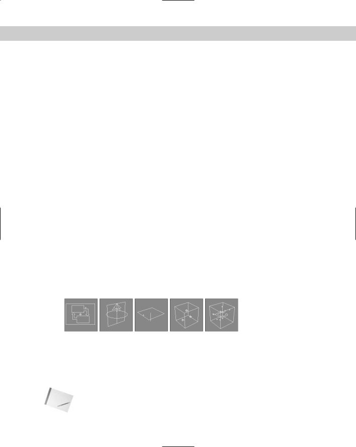
With the Particle Systems subcategory selected, click the button for the type of particle system that you want to use, and then click in a viewport to create the particle system emitter icon. The emitter icon is a gizmo that looks like a plane or a sphere and that defines the location in the system where the particles all originate. Attached to the icon is a single line that indicates the direction in which the particles move when generated. This line points by default toward the construction grid’s negative Z axis when first created. Figure 18-1 shows the emitter icons for each particle system type including, from left to right, Particle Flow Source, Super Spray, Spray and Snow and Blizzard (which all have the same emitter icon), PArray, and PCloud.
Figure 18-1: The emitter icons for each particle system type
You can transform these icons using the standard transform buttons on the main toolbar. Rotating an emitter changes the direction in which the particles initially move.
After an icon is created, you can set the number, shape, and size of the particles and define their motion in the Parameter rollouts. To apply a material to the particles, simply apply the material to the system’s icon. This material is applied to all particles included in the system.
Note |
Be aware that the particles are displayed as simple objects such as ticks or dots in the view- |
|
ports. To see the actual resulting particles, you need to render the scene file. |
Chapter 18 Creating Particles and Particle Flow |
515 |
You can set the parameters for the Max particle systems in the Create panel when they are first created or in the Modify panel at any time. The simpler systems, Spray and Snow, have a single Parameters rollout, but the advanced systems — Particle Flow Source, Super Spray, and Blizzard — include multiple Parameters rollouts. The PArray and PCloud systems have similar multiple rollouts, with a few subtle differences, and the Particle Flow system includes several rollouts, but most of the action is with the Particle Flow window. The following sections describe how to use these rollouts to set the parameters for the various particle systems.
Using the Spray and Snow Particle Systems
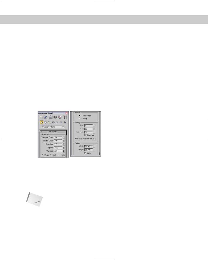
All I can say about the Spray and Snow particle systems is that “when it rains, it pours.” The Spray Parameters rollout, shown in Figure 18-2, includes values for the number of particles to be included in the system. These values can be different for the viewport and the renderer. By limiting the number of particles displayed in the viewport, you can make the viewport updates quicker. You can also specify the drop size, initial speed, and variation. The Variation value alters the spread of the particles’ initial speed and direction. A Variation value of 0 makes the particles travel in a straight line away from the emitter.
Figure 18-2: The Spray Parameters rollout holds the parameters for the Spray particle system.
Spray particles can be Drops, Dots, or Ticks, which affect how the particles look only in the viewport. Drops appear as streaks, Dots are simple points, and Ticks are small plus signs. You can also set how the particles are rendered — as Tetrahedron objects or as Facing objects (square faces that always face the viewer).
Note |
The Facing option is visible only in the Perspective view. |
The Timing values determine when the particles appear and how long the particles stay around. The Start Frame is the first frame where particles begin to appear, and the Life value determines the number of frames in which the particles are visible. When a particle’s lifetime is up, it disappears. The Birth Rate value lets you set how many new particles appear in each frame; you can use this setting or select the Constant option. The Constant option determines the Birth Rate value by dividing the total number of particles by the number of frames.

516 Part III Modeling
The emitter dimensions specify the width and height of the emitter gizmo. You can also hide the emitter with the Hide option.
Note |
The Hide option hides the emitter only in the viewports. Emitters are never rendered. |
The parameters for the Snow particle system are similar to the Spray particle system, except for a few unique settings. Snow can be set with a Tumble and Tumble Rate. The Tumble value can range from 0 to 1, with 1 causing a maximum amount of rotation. The Tumble Rate determines the speed of the rotation.
The Render options are also different for the Snow particle system. The three options are Six Point, Triangle, and Facing. The Six Point option renders the particle as a six-pointed star. Triangles and Facing objects are single faces.
Tutorial: Creating rain showers
One of the simplest uses for particle systems is to simulate rain or snow. In this tutorial, you use the Spray system to create rain and then learn how to use the Snow system to create snow.
To create a scene with rain using the Spray particle system, follow these steps:
1.Open the Simple rain.max file from the Chap 18 directory on the CD-ROM. This file includes an umbrella model created by Zygote Media.
2.Select the Create Particles Spray menu command, and drag the icon in the Top viewport to cover the entire scene. Position the icon above the objects, and make sure that the vector is pointing down toward the scene objects.
3.Open the Modify panel, and in the Parameters rollout, set the Render Count to 1000 and the Drop Size to 2. Keep the default speed of 10, and select the Drops option; these settings make the particles appear as streaks. Select the Tetrahedron Render method, and set the Start and Life values to 0 and 100, respectively.
Note |
To cover the entire scene with an average downpour, set the number of particles to 1000 for |
|
a 100-frame animation. |
4.Open the Material Editor (by pressing the M key), and drag a light-blue-colored material to the particle system icon.
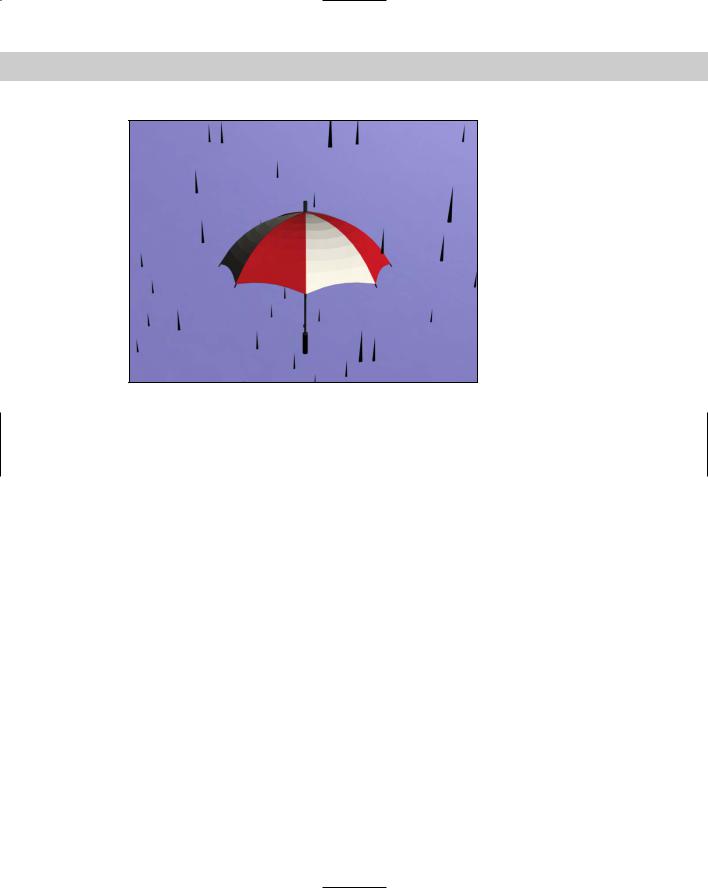
Figure 18-3 shows the results of this tutorial.
Tutorial: Creating a snow storm
Creating a snowstorm is very similar to what you did in the preceding tutorial. To create a snowstorm, use the Snow particle system with the same number of particles and apply a white material to the particle system.
Chapter 18 Creating Particles and Particle Flow |
517 |
Figure 18-3: Rain created with the Spray particle system
To create a scene with snow using the Snow particle system, follow these steps:
1.Open the Snowman in snowstorm.max file from the Chap 18 directory on the CD-ROM. This file includes a snowman created using primitive objects.
2.Select the Create Particles Snow menu command, and drag the icon in the Top viewport to cover the entire scene. Position the icon above the objects, and make sure that the vector is pointing down toward the scene objects.
3.Open the Modify panel, and in the Parameters rollout, set the Render Count to 1000 and the Flake Size to 6, and use the Six Point Render option. Select the Start and Life values to 0 and 100, respectively.
4.Open the Material Editor (by pressing the M key), and drag a white-colored material with some self-illumination added to the particle system gizmo.
Figure 18-4 shows the results of this tutorial.