

- •Preface
- •About This Book
- •Acknowledgments
- •Contents at a Glance
- •Contents
- •Relaxing at the Beach
- •Dressing the Scene
- •Animating Motion
- •Rendering the Final Animation
- •Summary
- •The Interface Elements
- •Using the Menus
- •Using the Toolbars
- •Using the Viewports
- •Using the Command Panel
- •Using the Lower Interface Bar Controls
- •Interacting with the Interface
- •Getting Help
- •Summary
- •Understanding 3D Space
- •Using the Viewport Navigation Controls
- •Configuring the Viewports
- •Working with Viewport Backgrounds
- •Summary
- •Working with Max Scene Files
- •Setting File Preferences
- •Importing and Exporting
- •Referencing External Objects
- •Using the File Utilities
- •Accessing File Information
- •Summary
- •Customizing Modify and Utility Panel Buttons
- •Working with Custom Interfaces
- •Configuring Paths
- •Selecting System Units
- •Setting Preferences
- •Summary
- •Creating Primitive Objects
- •Exploring the Primitive Object Types
- •Summary
- •Selecting Objects
- •Setting Object Properties
- •Hiding and Freezing Objects
- •Using Layers
- •Summary
- •Cloning Objects
- •Understanding Cloning Options
- •Mirroring Objects
- •Cloning over Time
- •Spacing Cloned Objects
- •Creating Arrays of Objects
- •Summary
- •Working with Groups
- •Building Assemblies
- •Building Links between Objects
- •Displaying Links and Hierarchies
- •Working with Linked Objects
- •Summary
- •Using the Schematic View Window
- •Working with Hierarchies
- •Setting Schematic View Preferences
- •Using List Views
- •Summary
- •Working with the Transformation Tools
- •Using Pivot Points
- •Using the Align Commands
- •Using Grids
- •Using Snap Options
- •Summary
- •Exploring the Modifier Stack
- •Exploring Modifier Types
- •Summary
- •Exploring the Modeling Types
- •Working with Subobjects
- •Modeling Helpers
- •Summary
- •Drawing in 2D
- •Editing Splines
- •Using Spline Modifiers
- •Summary
- •Creating Editable Mesh and Poly Objects
- •Editing Mesh Objects
- •Editing Poly Objects
- •Using Mesh Editing Modifiers
- •Summary
- •Introducing Patch Grids
- •Editing Patches
- •Using Modifiers on Patch Objects
- •Summary
- •Creating NURBS Curves and Surfaces
- •Editing NURBS
- •Working with NURBS
- •Summary
- •Morphing Objects
- •Creating Conform Objects
- •Creating a ShapeMerge Object
- •Creating a Terrain Object
- •Using the Mesher Object
- •Working with BlobMesh Objects
- •Creating a Scatter Object
- •Creating Connect Objects
- •Modeling with Boolean Objects
- •Creating a Loft Object
- •Summary
- •Understanding the Various Particle Systems
- •Creating a Particle System
- •Using the Spray and Snow Particle Systems
- •Using the Super Spray Particle System
- •Using the Blizzard Particle System
- •Using the PArray Particle System
- •Using the PCloud Particle System
- •Using Particle System Maps
- •Controlling Particles with Particle Flow
- •Summary
- •Understanding Material Properties
- •Working with the Material Editor
- •Using the Material/Map Browser
- •Using the Material/Map Navigator
- •Summary
- •Using the Standard Material
- •Using Shading Types
- •Accessing Other Parameters
- •Using External Tools
- •Summary
- •Using Compound Materials
- •Using Raytrace Materials
- •Using the Matte/Shadow Material
- •Using the DirectX 9 Shader
- •Applying Multiple Materials
- •Material Modifiers
- •Summary
- •Understanding Maps
- •Understanding Material Map Types
- •Using the Maps Rollout
- •Using the Map Path Utility
- •Using Map Instances
- •Summary
- •Mapping Modifiers
- •Using the Unwrap UVW modifier
- •Summary
- •Working with Cameras
- •Setting Camera Parameters
- •Summary
- •Using the Camera Tracker Utility
- •Summary
- •Using Multi-Pass Cameras
- •Creating Multi-Pass Camera Effects
- •Summary
- •Understanding the Basics of Lighting
- •Getting to Know the Light Types
- •Creating and Positioning Light Objects
- •Viewing a Scene from a Light
- •Altering Light Parameters
- •Working with Photometric Lights
- •Using the Sunlight and Daylight Systems
- •Using Volume Lights
- •Summary
- •Selecting Advanced Lighting
- •Using Local Advanced Lighting Settings
- •Tutorial: Excluding objects from light tracing
- •Summary
- •Understanding Radiosity
- •Using Local and Global Advanced Lighting Settings
- •Working with Advanced Lighting Materials
- •Using Lighting Analysis
- •Summary
- •Using the Time Controls
- •Working with Keys
- •Using the Track Bar
- •Viewing and Editing Key Values
- •Using the Motion Panel
- •Using Ghosting
- •Animating Objects
- •Working with Previews
- •Wiring Parameters
- •Animation Modifiers
- •Summary
- •Understanding Controller Types
- •Assigning Controllers
- •Setting Default Controllers
- •Examining the Various Controllers
- •Summary
- •Working with Expressions in Spinners
- •Understanding the Expression Controller Interface
- •Understanding Expression Elements
- •Using Expression Controllers
- •Summary
- •Learning the Track View Interface
- •Working with Keys
- •Editing Time
- •Editing Curves
- •Filtering Tracks
- •Working with Controllers
- •Synchronizing to a Sound Track
- •Summary
- •Understanding Your Character
- •Building Bodies
- •Summary
- •Building a Bones System
- •Using the Bone Tools
- •Using the Skin Modifier
- •Summary
- •Creating Characters
- •Working with Characters
- •Using Character Animation Techniques
- •Summary
- •Forward versus Inverse Kinematics
- •Creating an Inverse Kinematics System
- •Using the Various Inverse Kinematics Methods
- •Summary
- •Creating and Binding Space Warps
- •Understanding Space Warp Types
- •Combining Particle Systems with Space Warps
- •Summary
- •Understanding Dynamics
- •Using Dynamic Objects
- •Defining Dynamic Material Properties
- •Using Dynamic Space Warps
- •Using the Dynamics Utility
- •Using the Flex Modifier
- •Summary
- •Using reactor
- •Using reactor Collections
- •Creating reactor Objects
- •Calculating and Previewing a Simulation
- •Constraining Objects
- •reactor Troubleshooting
- •Summary
- •Understanding the Max Renderers
- •Previewing with ActiveShade
- •Render Parameters
- •Rendering Preferences
- •Creating VUE Files
- •Using the Rendered Frame Window
- •Using the RAM Player
- •Reviewing the Render Types
- •Using Command-Line Rendering
- •Creating Panoramic Images
- •Getting Printer Help
- •Creating an Environment
- •Summary
- •Creating Atmospheric Effects
- •Using the Fire Effect
- •Using the Fog Effect
- •Summary
- •Using Render Elements
- •Adding Render Effects
- •Creating Lens Effects
- •Using Other Render Effects
- •Summary
- •Using Raytrace Materials
- •Using a Raytrace Map
- •Enabling mental ray
- •Summary
- •Understanding Network Rendering
- •Network Requirements
- •Setting up a Network Rendering System
- •Starting the Network Rendering System
- •Configuring the Network Manager and Servers
- •Logging Errors
- •Using the Monitor
- •Setting up Batch Rendering
- •Summary
- •Compositing with Photoshop
- •Video Editing with Premiere
- •Video Compositing with After Effects
- •Introducing Combustion
- •Using Other Compositing Solutions
- •Summary
- •Completing Post-Production with the Video Post Interface
- •Working with Sequences
- •Adding and Editing Events
- •Working with Ranges
- •Working with Lens Effects Filters
- •Summary
- •What Is MAXScript?
- •MAXScript Tools
- •Setting MAXScript Preferences
- •Types of Scripts
- •Writing Your Own MAXScripts
- •Learning the Visual MAXScript Editor Interface
- •Laying Out a Rollout
- •Summary
- •Working with Plug-Ins
- •Locating Plug-Ins
- •Summary
- •Low-Res Modeling
- •Using Channels
- •Using Vertex Colors
- •Rendering to a Texture
- •Summary
- •Max and Architecture
- •Using AEC Objects
- •Using Architectural materials
- •Summary
- •Tutorial: Creating Icy Geometry with BlobMesh
- •Tutorial: Using Caustic Photons to Create a Disco Ball
- •Summary
- •mental ray Rendering System
- •Particle Flow
- •reactor 2.0
- •Schematic View
- •BlobMesh
- •Spline and Patch Features
- •Import and Export
- •Shell Modifier
- •Vertex Paint and Channel Info
- •Architectural Primitives and Materials
- •Minor Improvements
- •Choosing an Operating System
- •Hardware Requirements
- •Installing 3ds max 6
- •Authorizing the Software
- •Setting the Display Driver
- •Updating Max
- •Moving Max to Another Computer
- •Using Keyboard Shortcuts
- •Using the Hotkey Map
- •Main Interface Shortcuts
- •Dialog Box Shortcuts
- •Miscellaneous Shortcuts
- •System Requirements
- •Using the CDs with Windows
- •What’s on the CDs
- •Troubleshooting
- •Index

628 Part IV Materials and Maps
Figure 22-31: The Thin Wall Refraction map is applied to a magnifying glass.
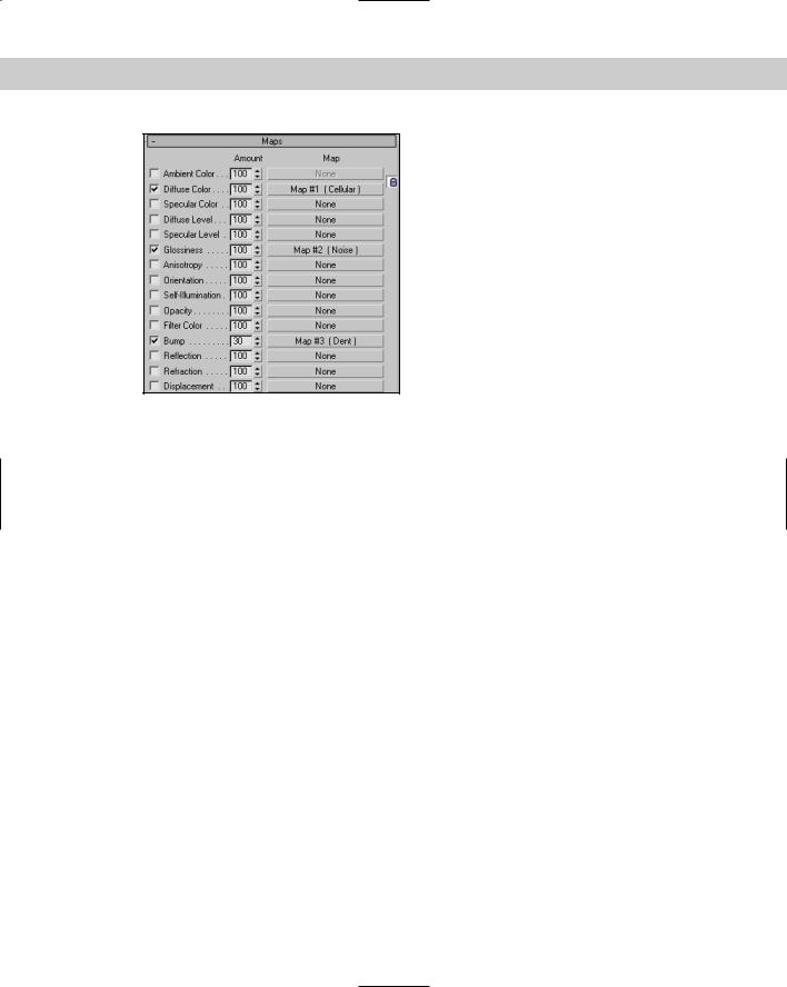
Using the Maps Rollout
Now that you’ve seen all the different types of maps that are available, we’ll revisit the Maps rollout (introduced in Chapter 20), shown in Figure 22-32, and cover it in more detail.
The Maps rollout is where you apply maps to the various materials. To use a map, click the Map button; this opens the Material/Map Browser where you can select the map to use. The Amount spinner sets the intensity of the map, and an option to enable or disable the map is available. For example, a white material with a red Diffuse map set at 50 percent Intensity results in a pink material.
The available maps in the Maps rollout depend on the type of material and the Shader that you are using. Raytrace materials have many more available maps than the standard material. Some of the common mapping types found in the Maps rollout are discussed in this section.
Ambient mapping
Ambient mapping replaces the ambient color component of the base material. You can use this feature to make an object’s shadow appear as a map. Diffuse mapping (discussed next) also affects the Ambient color. A lock button in the Maps rollout enables you to lock these two mappings together.
Chapter 22 Adding Material Details with Maps |
629 |
Figure 22-32: The Maps rollout can turn maps on or off.
Diffuse mapping
Diffuse mapping replaces the diffuse color component of the base material. This is the main color used for the object. When you select a map such as Wood, the object appears to be created out of wood. As mentioned previously, diffuse mapping can also affect the Ambient color if the lock button is selected.
Diffuse Level mapping
Diffuse Level mapping changes the diffuse color level from 0, where the map is black, to a maximum, where the map is white. This mapping is available only with the Anisotropic, Oren- Nayar-Blinn, and Multi-Level Shaders.
Diffuse Roughness mapping
Roughness mapping sets the roughness value of the material from 0, where the map is black, to a maximum, where the map is white. This mapping is available only with the Oren-Nayar- Blinn and Multi-Layer Shaders.
Specular mapping
Specular mapping replaces the specular color component of the base material. This option enables you to include a different color or image in place of the specular color. It is different from the Specular Level and Glossiness mappings, which also affect the specular highlights.
630 Part IV Materials and Maps
Specular Level mapping
Specular Level mapping controls the intensity of the specular highlights from 0, where the map is black, to 1, where the map is white. For the best effect, apply this mapping along with the Glossiness mapping.
Glossiness mapping
Glossiness mapping defines where the specular highlights will appear. You can use this option to make an object appear older by diminishing certain areas. Black areas on the map show the non-glossy areas, and white areas are where the glossiness is at a maximum.
Self-Illumination mapping
Self-Illumination mapping makes certain areas of an object glow, and, because they glow, they won’t receive any lighting effects, such as highlights or shadows. Black areas represent areas that have no self-illumination, and white areas receive full self-illumination.
Opacity mapping
Opacity mapping determines which areas are visible and which are transparent. Black areas for this map are transparent, and white areas are opaque. This mapping works in conjunction with the Opacity value in the Basic Parameters rollout. Transparent areas, even if perfectly transparent, still receive specular highlights.
Filter color mapping
Filter color mapping is used to color transparent areas for creating materials such as colored glass. White light that is cast through an object using filter color mapping is colored with the filter color.
Anisotropy mapping
Anisotropy mapping can control the shape of an anisotropy highlight. This mapping is available only with the Anisotropic and Multi-Layer Shaders.
Orientation mapping
Orientation mapping controls an anisotropic highlight’s position. Anisotropic highlights are elliptical, and this mapping can position them at a different angle. Orientation mapping is available only with the Anisotropic and Multi-Layer Shaders.
Metalness mapping
Metalness mapping controls how metallic an area looks. It specifies metalness values from 0, where the map is black, to a maximum, where the map is white. This mapping is available only with the Strauss Shader.

Chapter 22 Adding Material Details with Maps |
631 |
Bump mapping
Bump mapping uses the intensity of the bitmap to raise or indent the surface of an object. The white areas of the map are raised, and darker areas are lowered. Although bump mapping appears to alter the geometry, it actually doesn’t affect the surface geometry.
Reflection mapping
Reflection mapping reflects images off the surface as a mirror does. The three different types of Reflection mapping are Basic, Automatic, and Flat Mirror. Basic reflection mapping simulates the reflection of an object’s surroundings. Automatic reflection mapping projects the map outward from the center of the object. Flat-Mirror reflection mapping reflects a mirror image off a series of coplanar faces.
Reflection mapping doesn’t need mapping coordinates because the coordinates are based on world coordinates and not on object coordinates. Therefore, the map appears different if the object is moved, which is how reflections work in the real world.
Refraction mapping
Refraction mapping bends light and displays images through a transparent object, in the same way a room appears through a glass of water. The amount of this effect is controlled by a value called the Index of Refraction. This value is set in the parent material’s Extended Parameters rollout.
Displacement mapping
You can use displacement mapping, unlike bump mapping, to change the geometry of an object. The white areas of the map are pushed outward, and the dark areas are pushed in. The amount of the surface that is displaced is based on a percentage of the diagonal that makes up the bounding box of the object. Displacement mapping can be applied only to patches, Editable Meshes, and NURBS objects. For other object types, you can use displacement mapping only after the Disp Approx modifier has been applied.
Displacement mapping isn’t visible in the viewports unless the Displace NURBS (for NURBS objects) or the Displace Mesh (for Editable Meshes) modifiers have been applied.
Tutorial: Creating space textures
“Space . . . the final frontier.” Space is a great place to start creating and using new materials. With objects floating in space, you don’t need to worry about lining things up, and modeling planets is easy because they are made from simple spheres — the materials are what make the planet spheres look good. So, as an example of creating new materials, let’s create several new “space” materials.
In this tutorial, you learn how to make textures for the sun, a moon, and several different planets. To create several planetary textures, follow these steps:
1.Open the Space textures.max file from the Chap 22 directory on the CD-ROM. This file contains five simple spheres that represent some space planets.

632 Part IV Materials and Maps
2.Press the M key to open the Material Editor, select the first sample slot, and name the material Sun. Click the map button to the right of the Diffuse color swatch to open the Material/Map Browser, and double-click the Noise map. In the Noise Parameters rollout, select the Fractal option and set the Size to 20 and the Levels to 10. Choose an orange color for Color #1 and black for Color #2. Next, open the Maps rollout and drag the Noise map from the Diffuse mapping to the Self-Illumination mapping. A small dialog box opens, enabling you to Copy the map as an Instance or a Copy or Swap the maps. Select the Copy option, and click OK. Drag the material to one of the spheres in the scene. Click the Go to Parent button to return to the base Sun material.
Tip |
Double-click the sample slot to open a magnified view of the material. This lets you see the |
|
details up close. |
3.Select the second sample slot, and name it Planet 1. Then click the map button to the right of the Diffuse color swatch to open the Material/Map Browser again, and doubleclick the Planet map type. In the Planet Parameters rollout, select three shades of blue for the Water Colors and five shades of green for the Land Colors. Set the Continent Size to 20, and enable the Blend Water/Land option. Drag the material to another one of the spheres in the scene.
4.Select the third sample slot, and name it Planet 2. Then click the map button to the right of the Diffuse color swatch to open the Material/Map Browser, and double-click the Planet map type again. In the Planet Parameters rollout, select shades of orange and brown for both the water and landmass of this planet. Set the Continent Size to 40, and enable the Blend Water/Land option. Drag the material to one of the spheres in the scene.
5.Select the fourth sample slot, and name it Planet 3. Then click the map button to the right of the Diffuse color swatch, and double-click the Planet map type once again. For this planet, select different shades of red. Set the Continent Size to 80, the Island Factor to 40, and the Ocean Percent to 20, and disable the Blend Water/Land option. Drag the material to one of the spheres in the scene.
6.Select the fifth sample slot, and name it Planet 4. Then click the map button to the right of the Diffuse color swatch, and double-click on the Swirl map type from the Material/Map Browser. In the Swirl Parameters rollout, select two colors for the Swirl and set the Swirl Intensity to 5.0. For the Swirl color, click the map button and select the Noise map. For the Noise map, set the Size value to 30 and select the Turbulence option. Drag the material to one of the spheres in the scene.
7.Select the sixth sample slot, and name it Moon. Then click the Diffuse color map button, and select Smoke from the Material/Map Browser. Set the Size value to 20, and click the map button for Color #1. Select the Noise map. Set the Size value to 25, and select the Turbulence option. Drag the material to one of the spheres in the scene.
8.Select the seventh sample slot (you need to drag the scroll bar to the right of the sample slots down to access the next row of sample slots), and name it Star Background. Then click the map button to the right of the Diffuse color swatch, and select Noise. In the Noise Parameters rollout, select the Fractal option and set the Size value to 2.0, the High value to 0.5, and the Levels to 2.0. Click the Swap button until Color #2 is black. In the Output rollout, set the Output Amount to 2.0. Choose the Rendering Environment menu command (or press the 8 key) to open the Environment dialog box. Drag the Noise map from the Material Type button to the Environment Map button at the top of the dialog box, and select the Use Map option.
Figure 22-33 shows the planets in space as a rendered image.

Chapter 22 Adding Material Details with Maps |
633 |
Figure 22-33: Using a variety of techniques, you can create an assortment of different space textures.
Tutorial: Aging objects for realism
I don’t know whether your toolbox is well worn like mine — it must be the hostile environment that it is always in (or all the things I keep dropping in and on it). To render a toolbox with nice specular highlights just doesn’t feel right. This tutorial shows a few ways to age an object so that it looks older.
To add maps to make an object look old, follow these steps:
1.Open the Toolbox.max file from the Chap 22 directory on the CD-ROM. This file contains a simple toolbox mesh created using extruded splines.
2.Press the M key to open the Material Editor, and select the first sample slot. Select the Metal shader from the drop-down list in the Shader Basic Parameters rollout. In the Metal Basic Parameters rollout, set the Diffuse color to a nice, shiny red and increase the Specular Level to 97 and Glossiness value to 59. Name the material Toolbox.
3.In the Maps rollout, click the button for the Glossiness mapping and double-click on the Splat map from the Material/Map Browser. In the Splat Parameters rollout, set the Size value to 100 and change Color #1 to a rust color and Color #2 to white.
4.Click on the Go to Parent button (which is located above the material Type button) to get back the Maps rollout for the base material. In the Maps rollout, click the Bump mapping button and double-click the Dent map from the Material/Map Browser. In the Dent Parameters rollout, set the Size value to 200, Color #1 to black, and Color #2 to white.