

- •Preface
- •About This Book
- •Acknowledgments
- •Contents at a Glance
- •Contents
- •Relaxing at the Beach
- •Dressing the Scene
- •Animating Motion
- •Rendering the Final Animation
- •Summary
- •The Interface Elements
- •Using the Menus
- •Using the Toolbars
- •Using the Viewports
- •Using the Command Panel
- •Using the Lower Interface Bar Controls
- •Interacting with the Interface
- •Getting Help
- •Summary
- •Understanding 3D Space
- •Using the Viewport Navigation Controls
- •Configuring the Viewports
- •Working with Viewport Backgrounds
- •Summary
- •Working with Max Scene Files
- •Setting File Preferences
- •Importing and Exporting
- •Referencing External Objects
- •Using the File Utilities
- •Accessing File Information
- •Summary
- •Customizing Modify and Utility Panel Buttons
- •Working with Custom Interfaces
- •Configuring Paths
- •Selecting System Units
- •Setting Preferences
- •Summary
- •Creating Primitive Objects
- •Exploring the Primitive Object Types
- •Summary
- •Selecting Objects
- •Setting Object Properties
- •Hiding and Freezing Objects
- •Using Layers
- •Summary
- •Cloning Objects
- •Understanding Cloning Options
- •Mirroring Objects
- •Cloning over Time
- •Spacing Cloned Objects
- •Creating Arrays of Objects
- •Summary
- •Working with Groups
- •Building Assemblies
- •Building Links between Objects
- •Displaying Links and Hierarchies
- •Working with Linked Objects
- •Summary
- •Using the Schematic View Window
- •Working with Hierarchies
- •Setting Schematic View Preferences
- •Using List Views
- •Summary
- •Working with the Transformation Tools
- •Using Pivot Points
- •Using the Align Commands
- •Using Grids
- •Using Snap Options
- •Summary
- •Exploring the Modifier Stack
- •Exploring Modifier Types
- •Summary
- •Exploring the Modeling Types
- •Working with Subobjects
- •Modeling Helpers
- •Summary
- •Drawing in 2D
- •Editing Splines
- •Using Spline Modifiers
- •Summary
- •Creating Editable Mesh and Poly Objects
- •Editing Mesh Objects
- •Editing Poly Objects
- •Using Mesh Editing Modifiers
- •Summary
- •Introducing Patch Grids
- •Editing Patches
- •Using Modifiers on Patch Objects
- •Summary
- •Creating NURBS Curves and Surfaces
- •Editing NURBS
- •Working with NURBS
- •Summary
- •Morphing Objects
- •Creating Conform Objects
- •Creating a ShapeMerge Object
- •Creating a Terrain Object
- •Using the Mesher Object
- •Working with BlobMesh Objects
- •Creating a Scatter Object
- •Creating Connect Objects
- •Modeling with Boolean Objects
- •Creating a Loft Object
- •Summary
- •Understanding the Various Particle Systems
- •Creating a Particle System
- •Using the Spray and Snow Particle Systems
- •Using the Super Spray Particle System
- •Using the Blizzard Particle System
- •Using the PArray Particle System
- •Using the PCloud Particle System
- •Using Particle System Maps
- •Controlling Particles with Particle Flow
- •Summary
- •Understanding Material Properties
- •Working with the Material Editor
- •Using the Material/Map Browser
- •Using the Material/Map Navigator
- •Summary
- •Using the Standard Material
- •Using Shading Types
- •Accessing Other Parameters
- •Using External Tools
- •Summary
- •Using Compound Materials
- •Using Raytrace Materials
- •Using the Matte/Shadow Material
- •Using the DirectX 9 Shader
- •Applying Multiple Materials
- •Material Modifiers
- •Summary
- •Understanding Maps
- •Understanding Material Map Types
- •Using the Maps Rollout
- •Using the Map Path Utility
- •Using Map Instances
- •Summary
- •Mapping Modifiers
- •Using the Unwrap UVW modifier
- •Summary
- •Working with Cameras
- •Setting Camera Parameters
- •Summary
- •Using the Camera Tracker Utility
- •Summary
- •Using Multi-Pass Cameras
- •Creating Multi-Pass Camera Effects
- •Summary
- •Understanding the Basics of Lighting
- •Getting to Know the Light Types
- •Creating and Positioning Light Objects
- •Viewing a Scene from a Light
- •Altering Light Parameters
- •Working with Photometric Lights
- •Using the Sunlight and Daylight Systems
- •Using Volume Lights
- •Summary
- •Selecting Advanced Lighting
- •Using Local Advanced Lighting Settings
- •Tutorial: Excluding objects from light tracing
- •Summary
- •Understanding Radiosity
- •Using Local and Global Advanced Lighting Settings
- •Working with Advanced Lighting Materials
- •Using Lighting Analysis
- •Summary
- •Using the Time Controls
- •Working with Keys
- •Using the Track Bar
- •Viewing and Editing Key Values
- •Using the Motion Panel
- •Using Ghosting
- •Animating Objects
- •Working with Previews
- •Wiring Parameters
- •Animation Modifiers
- •Summary
- •Understanding Controller Types
- •Assigning Controllers
- •Setting Default Controllers
- •Examining the Various Controllers
- •Summary
- •Working with Expressions in Spinners
- •Understanding the Expression Controller Interface
- •Understanding Expression Elements
- •Using Expression Controllers
- •Summary
- •Learning the Track View Interface
- •Working with Keys
- •Editing Time
- •Editing Curves
- •Filtering Tracks
- •Working with Controllers
- •Synchronizing to a Sound Track
- •Summary
- •Understanding Your Character
- •Building Bodies
- •Summary
- •Building a Bones System
- •Using the Bone Tools
- •Using the Skin Modifier
- •Summary
- •Creating Characters
- •Working with Characters
- •Using Character Animation Techniques
- •Summary
- •Forward versus Inverse Kinematics
- •Creating an Inverse Kinematics System
- •Using the Various Inverse Kinematics Methods
- •Summary
- •Creating and Binding Space Warps
- •Understanding Space Warp Types
- •Combining Particle Systems with Space Warps
- •Summary
- •Understanding Dynamics
- •Using Dynamic Objects
- •Defining Dynamic Material Properties
- •Using Dynamic Space Warps
- •Using the Dynamics Utility
- •Using the Flex Modifier
- •Summary
- •Using reactor
- •Using reactor Collections
- •Creating reactor Objects
- •Calculating and Previewing a Simulation
- •Constraining Objects
- •reactor Troubleshooting
- •Summary
- •Understanding the Max Renderers
- •Previewing with ActiveShade
- •Render Parameters
- •Rendering Preferences
- •Creating VUE Files
- •Using the Rendered Frame Window
- •Using the RAM Player
- •Reviewing the Render Types
- •Using Command-Line Rendering
- •Creating Panoramic Images
- •Getting Printer Help
- •Creating an Environment
- •Summary
- •Creating Atmospheric Effects
- •Using the Fire Effect
- •Using the Fog Effect
- •Summary
- •Using Render Elements
- •Adding Render Effects
- •Creating Lens Effects
- •Using Other Render Effects
- •Summary
- •Using Raytrace Materials
- •Using a Raytrace Map
- •Enabling mental ray
- •Summary
- •Understanding Network Rendering
- •Network Requirements
- •Setting up a Network Rendering System
- •Starting the Network Rendering System
- •Configuring the Network Manager and Servers
- •Logging Errors
- •Using the Monitor
- •Setting up Batch Rendering
- •Summary
- •Compositing with Photoshop
- •Video Editing with Premiere
- •Video Compositing with After Effects
- •Introducing Combustion
- •Using Other Compositing Solutions
- •Summary
- •Completing Post-Production with the Video Post Interface
- •Working with Sequences
- •Adding and Editing Events
- •Working with Ranges
- •Working with Lens Effects Filters
- •Summary
- •What Is MAXScript?
- •MAXScript Tools
- •Setting MAXScript Preferences
- •Types of Scripts
- •Writing Your Own MAXScripts
- •Learning the Visual MAXScript Editor Interface
- •Laying Out a Rollout
- •Summary
- •Working with Plug-Ins
- •Locating Plug-Ins
- •Summary
- •Low-Res Modeling
- •Using Channels
- •Using Vertex Colors
- •Rendering to a Texture
- •Summary
- •Max and Architecture
- •Using AEC Objects
- •Using Architectural materials
- •Summary
- •Tutorial: Creating Icy Geometry with BlobMesh
- •Tutorial: Using Caustic Photons to Create a Disco Ball
- •Summary
- •mental ray Rendering System
- •Particle Flow
- •reactor 2.0
- •Schematic View
- •BlobMesh
- •Spline and Patch Features
- •Import and Export
- •Shell Modifier
- •Vertex Paint and Channel Info
- •Architectural Primitives and Materials
- •Minor Improvements
- •Choosing an Operating System
- •Hardware Requirements
- •Installing 3ds max 6
- •Authorizing the Software
- •Setting the Display Driver
- •Updating Max
- •Moving Max to Another Computer
- •Using Keyboard Shortcuts
- •Using the Hotkey Map
- •Main Interface Shortcuts
- •Dialog Box Shortcuts
- •Miscellaneous Shortcuts
- •System Requirements
- •Using the CDs with Windows
- •What’s on the CDs
- •Troubleshooting
- •Index
500 Part III Modeling
Figure 17-21: A log cabin built using Boolean objects
Creating a Loft Object
Lofting is a term that comes from the shipbuilding industry. It describes a method for building ships that creates and positions the cross sections and then attaches a surface or skin along the length of the cross sections.
To create a Loft object, you need to have at least two spline shapes: one shape that defines the path of the Loft and a second shape that defines its cross section. After the shapes are created, select the Create Compound menu command. A Loft button is enabled if two or more splines are present in the viewport.
Using the Get Shape and Get Path buttons
After you click the Loft button, the Creation Method rollout displays the Get Path and Get Shape buttons, which you use to specify which spline is the path and which spline is the cross section. Select a spline, and then click either the Get Path button or the Get Shape button. If you click the Get Shape button, the selected spline is the path and the next spline shape you select is the cross section. If you click the Get Path button, the selected spline is the shape and the next spline shape you select is the path.
Note After you click the Get Path or Get Spline button, although the cursor changes when you’re over a valid spline, not all spline shapes can be used to create Loft objects. For example, you cannot use a spline created with the Donut button as a path.
Chapter 17 Building Compound Objects 501
When creating a Loft object with the Get Shape and Get Path buttons, you can specify either to Move the spline shape or to create a Copy or an Instance of it. The Move option replaces both splines with a Loft object. The Copy option leaves both splines in the viewport and creates a new Loft object. The Instance maintains a link between the spline and the Loft object. This link enables you to modify the original spline. The Loft object is updated automatically.
The vertex order of the path spline is important. The Loft object is created starting at the vertex numbered 1.
Note |
You can tell which vertex is the first by enabling Vertex Numbering in the Selection rollout of |
|
an editable spline. |
Controlling surface parameters
All Loft objects include the Surface Parameters rollout. Using this rollout, you can set the smoothing of the Loft object with two different options: Smooth Length and Smooth Width. You can use the Mapping options to control the mapping of textures by setting values for the number of times the map repeats over the Length or Width of the Loft. The Normalize option applies the map to the surface evenly or proportionately according to the shape’s vertex spacing. You can set the Loft object to automatically generate Material and Shape IDs, and you can specify the output of the Loft to be either a Patch or Mesh.
Changing path parameters
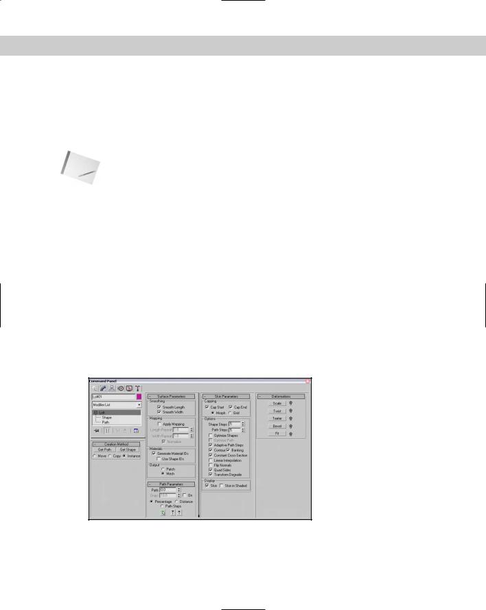
The Path Parameters rollout, shown in Figure 17-22, lets you position several different crosssectional shapes at different positions along the Loft path. The Path value indicates either the Distance or Percentage along the path where this new shape should be located. The Snap option, if turned on, enables you to snap to consistent distances along the path. The Path Steps option enables you to place new shapes at steps along the path where the vertices are located. Each path will have a different number of steps depending on its complexity.
Figure 17-22: The Loft compound object rollouts

502 Part III Modeling
The viewport displays a small yellow X at the location where the new cross-sectional shape will be inserted. At the bottom of the rollout are three buttons, which are illustrated and described in Table 17-1.
Table 17-1: Path Rollout Buttons
Toolbar Button Name |
Description |
|
|
Pick Shape |
Selects a new cross-section spline to be inserted at the specified |
|
location |
Previous Shape |
Moves to the previous cross-section shape along the Loft path |
Next Shape |
Moves to the next cross-section shape along the Loft path |
|
|
Setting skin parameters
The Skin Parameters rollout includes many options for determining the complexity of the Loft skin. You can specify whether to cap either end of the Loft using the Cap Start and/or Cap End options. The caps can be either Morph or Grid type.
This rollout also includes many options for controlling the look of the skin. These include the following:
Shape and Path Steps: Sets the number of segments that appear in each vertex’s crosssectional shape and between each division along the path. The straight segments are ignored if the Optimize Path option is selected.
Optimize Shapes and Paths: Reduces the Loft’s complexity by deleting any unneeded edges or vertices.
Adaptive Path Steps: Automatically determines the number of steps to use for the path.
Contour: Determines how the cross-sectional shapes line up with the path. If this option is enabled, the cross section is aligned to be perpendicular to the path at all times. If disabled, this option causes the cross-sectional shapes to maintain their orientation as the path is traversed.
Banking: Causes the cross-section shape to rotate as the path bends.
Constant Cross-Section: Scales the cross-sectional shapes in order to maintain a uniform width along the path. Turning off this option causes the cross sections to pinch at any sharp angles along the path.
Linear Interpolation: Causes straight linear edges to appear between different crosssectional shapes. Turning off this option causes smooth curves to connect various shapes.

Chapter 17 Building Compound Objects 503
Flip Normals: Used to correct difficulties that would appear with the normals. Often the normals are flipped accidentally when the Loft is created.
Quad Sides: Creates four-sided polygons to connect to adjacent cross-section shapes with the same number of sides.
Transform Degrade: Makes the Loft skin disappear when subobjects are transformed. This feature can help you better visualize the cross-sectional area while it is being moved.
The Display options at the bottom of the Skin Parameters rollout give you the choice of displaying the skin in all viewports or displaying the Loft skin only in the viewports with shading turned on.
Tutorial: Designing a slip-proof hanger
As an example of creating a Loft object with different cross-sectional shapes, we design a new hanger that includes some rough edges along its bottom section to keep slacks from sliding off.
To design a hanger Loft object with different cross sections, follow these steps:
1.Open the Lofted slip-proof hanger.max from the Chap 17 directory on the CD-ROM. This file includes a spline outline of a hanger and two simple shapes.
2.Select the hanger spline, and choose the Create Compound Loft menu command.
3.In the Creation Method rollout, click the Get Shape button and then click the small circle shape (make sure that the Copy option is selected).
This lofts the entire hanger with a circular cross section.
4.In the Path Parameters rollout, select the Path Steps option. A dialog box appears warning that this may change the relocate shapes. Click OK to continue. Increment the Path value until the yellow X marker in the viewport is positioned at the beginning of the hanger’s bottom bar (at Step 53 for this tutorial). Click the Get Shape button again, and click the small circular shape again.
This extends the circular cross section from the start at Step 0 to Step 53.
5.Increment the Path value by 1 to Step 54, click the Get Shape button, and select the star shape. This makes the remainder of the hanger use a star-shaped cross section. Increment the Path value again to the end of the hanger’s bottom bar (at Step 60), click the Get Shape button, and select the star shape again to end the star cross section.
Note |
If you forget to start and end a section with the same cross section, the loft blends between |
|
the two different cross sections. |
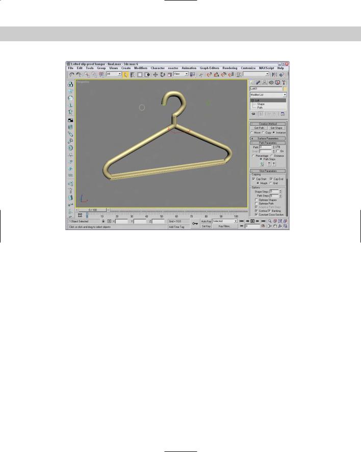
6.Open the Modify panel, increment the Path value a final time to Step 61, click the Get Shape button, and click the circular shape. Click the Pick Shape icon button at the bottom of the Path Parameters dialog box to change the cross section of the hanger to the end of the path. Right-click in the viewport to exit Get Shape mode.
Figure 17-23 shows the finished designer hanger.
504 Part III Modeling
Figure 17-23: A lofted hanger created with two different cross-sectional shapes
Deforming Loft objects
When you select a Loft object and open the Modify panel, the Deformation rollout appears. This rollout includes five buttons that let you Scale, Twist, Teeter, Bevel, and Fit the crosssection shapes along the path. All five buttons open similar graph windows that include control points and a line that represents the amount of the effect to apply. Next to each button is a toggle button with a light switch on it. This button enables or disables the respective effect.
The Deformation window interface
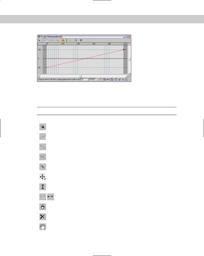
All five deformation options use the same basic window and controls. The lines within the window represent the length of the path. As an example of the Deformation window interface, Figure 17-24 shows the Scale Deformation window.
Dragging the curve directly can modify the deformation curve. You can also insert control points at any location along the curve. These control points can be one of three different types: Corner, Bézier Corner, or Bézier Smooth. Bézier type points have handles for controlling the curvature at the point. To change the point type, select the point and right-click. Then make your selection from the pop-up menu. The end points must always be either Corner or Bézier Corner type.
To move a control point, select and drag it or enter a horizontal and/or vertical value in the fields at the bottom of the window.
Chapter 17 Building Compound Objects 505
Figure 17-24: The Deformation dialog box interface lets you control the cross section over the length of the path.
Table 17-2 describes the buttons at the top of the Deformation window.
Table 17-2: Deformation Dialog Box Buttons
Toolbar Button Name |
Description |
|
|
Make Symmetrical |
Links the two curves so that changes made to one curve |
|
are also made to the other |
Display X-Axis |
Makes the line controlling the X axis visible |
Display Y-Axis |
Makes the line controlling the Y axis visible |
Display XY axes |
Makes both lines visible |
Swap Deform Curves |
Switches the lines |
Move Control Point |
Enables you to move control points, and includes flyouts |
|
for horizontal and vertical movements |
Scale Control Point |
Scales the selected control point |
Insert Corner Point, |
Inserts new points on a deformation curve |
Insert Bézier Point |
|
Delete Control Point |
Deletes the current control point |
Reset Curve |
Returns the original curve |
Pan |
Pans the curve as the mouse is dragged |
Continued
506 Part III Modeling
Table 17-2 (continued)
Toolbar Button Name |
Description |
|
|
Zoom Extents |
Zooms to display the entire curve |
Zoom Extents Horizontal |
Zooms to display the entire horizontal curve range |
Zoom Extents Vertical |
Zooms to display the entire vertical curve range |
Zoom Horizontal |
Zooms on the horizontal curve range |
Zoom Vertical |
Zooms on the vertical curve range |
Zoom |
Zooms in and out as the mouse is dragged |
Zoom Region |
Zooms to the region specified by the mouse |
|
|
Note Several buttons are disabled on the Twist and Bevel Deformation windows because these dialog boxes have only one deformation curve.
At the bottom of the Deformation dialog boxes are two value fields. The value fields display the X and Y coordinate values for the currently selected point. The navigation buttons enable you to pan and zoom within the dialog box.
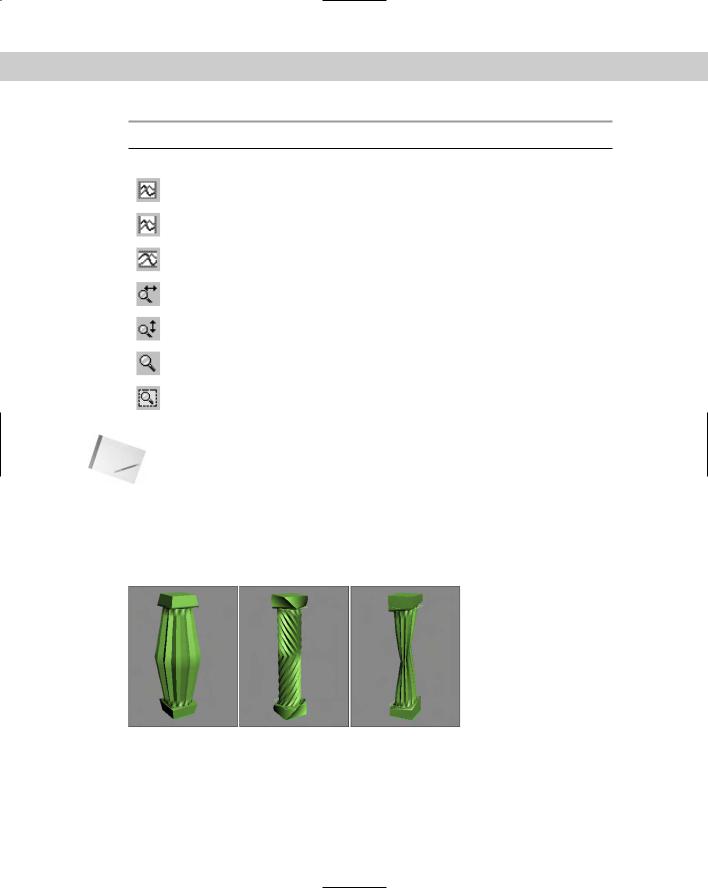
Figure 17-25 and Figure 17-26 show each of the various deformation options applied to a lofted column.
Figure 17-25: The Loft compound object deformation options: Scale, Twist, and Teeter
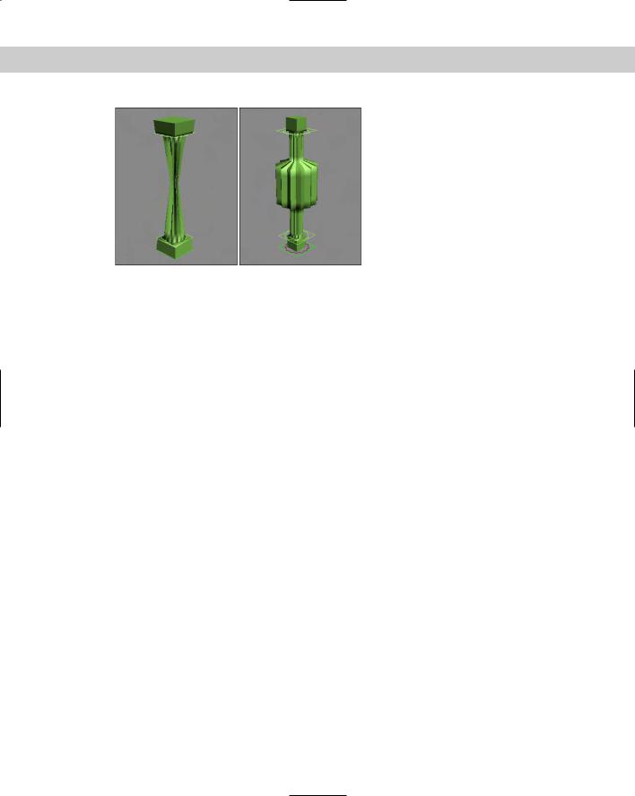
Chapter 17 Building Compound Objects 507
Figure 17-26: The Loft compound object deformation options: Bevel and Fit
Scale Deformation
The Scale Deformation window can alter the relative scale of the Loft object at any point along its path. This window includes two lines: one red and one green. The red line displays the X-axis scale, and the green line displays the Y-axis scale. By default, both lines are positioned equally at the 100 percent value. Specifying a value greater than 100 percent increases the scale, and specifying a value less than 100 percent has the opposite effect.
Twist Deformation
The Twist Deformation rotates one cross section relative to the others and can be used to create an object that spirals along its path. This option is similar to the Banking option, which can also produce rotations about the path.
The Twist Deformation window includes only one red line representing the rotation value. By default, this line is set to a 0-degree rotation value. Positive values result in counterclockwise rotations, and negative values have the opposite effect.
Teeter Deformation
Teeter Deformation rotates a cross section so that its outer edges move closer to the path. This is done by rotating the cross section about its local X or Y axis. The result is similar to that produced by the Contour option.
The Teeter Deformation window includes two lines: one red and one green. The red line displays the X-axis rotation, and the green line displays the Y-axis rotation. By default, both lines are positioned equally at the 0 degree value. Positive values result in counterclockwise rotations, and negative values have the opposite effect.
508 Part III Modeling
Bevel Deformation
Bevel Deformation bevels the cross-section shapes. The Bevel Deformation window includes only one red line representing the amount of bevel that is applied. By default, this line is set to a 0 value. Positive values increase the bevel amount, which equals a reduction in the shape area, and negative values have the opposite effect.
You can also use the Bevel Deformation window to select three different types of beveling: Normal, Adaptive Linear, and Adaptive Cubic. Table 17-3 shows and describes the buttons for these three beveling types. You can select them from a flyout at the right end of the window.
Table 17-3: Bevel Deformation Buttons
Toolbar Button Name |
Description |
|
|
Normal Bevel |
Produces a normal bevel with parallel edges, regardless of the |
|
path angle |
Adaptive (Linear) |
Alters the bevel linearly, based on the path angle |
Adaptive (Cubic) |
Alters the bevel using a cubic spline based on the path angle |
|
|
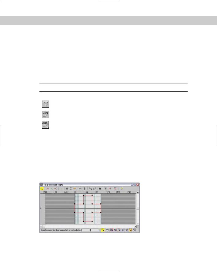
Fit Deformation
The Fit Deformation window, shown in Figure 17-27, lets you specify a profile for the outer edges of the cross-section shapes to follow. This window includes two lines: one red and one green. The red line displays the X-axis scale, and the green line displays the Y-axis scale. By default, both lines are positioned equally at the 100 percent value. Specifying a value that is greater than 100 percent increases the scale, and specifying a value that is less than 100 percent has the opposite effect.
Figure 17-27: A Loft object with Fit Deformation applied
The Fit Deformation window includes ten buttons unique to it that are used to control the profile curves. These buttons are illustrated and described in Table 17-4.
Chapter 17 Building Compound Objects 509
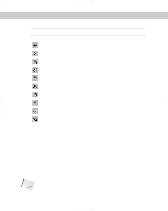
Table 17-4: Fit Deformation Dialog Box Buttons
Toolbar Button Name |
Description |
|
|
Mirror Horizontally |
Mirrors the selection horizontally |
Mirror Vertically |
Mirrors the selection vertically |
Rotate 90 degrees CCW |
Rotates the selection 90 degrees counterclockwise |
Rotate 90 degrees CW |
Rotates the selection 90 degrees clockwise |
Delete Control Point |
Deletes the selected control point |
Reset Curve |
Returns the curve to its original form |
Delete Curve |
Deletes the selected curve |
Get Shape |
Selects a separate spline to use as a profile |
Generate Path |
Replaces the current path with a straight line |
Lock Aspect |
Maintains the relationship between height and width |
|
|
Modifying Loft subobjects
When you select a Loft object, you can work with its subobjects in the Modify panel. The subobjects for a Loft include Path and Shape. The Path subobject opens the Path Commands rollout. This rollout has only a single button — Put — for creating a copy of the Loft path. If you click this button, the Put To Scene dialog box appears, enabling you to give the path a name and select to create it as a Copy or an Instance.
If your path is created as an Instance, you can edit the instance to control the Loft path.
The Shape subobject opens the Shape Commands rollout. This rollout also includes a Put button along with some additional controls. The Path Level value adjusts the shape’s position on the path. The Compare button opens the Compare dialog box, which is discussed in the following section. The Reset button returns the shape to its former state before any rotation or scaling has taken place, and the Delete button deletes the shape entirely.
Note |
You cannot delete a shape if it is the only shape in the Loft object. |
510 Part III Modeling
The Shape Commands rollout also includes six Align buttons for aligning the shape to the Center, Default, Left, Right, Top, and Bottom. For the Loft object local coordinates, Left and Right move the shape along the X axis, and Top and Bottom move it along the Y axis.
Comparing shapes
The Compare dialog box superimposes selected cross-sectional shapes included in a Loft object on top of one another to check their center alignment. The button in the upper-left corner is the Pick Shape button. This button lets you select which shapes to display in the dialog box. The button to its right is the Delete Shape button, for removing a shape from the dialog box. Figure 17-28 shows the Compare dialog box with the two shapes from the pillar example selected. Notice that the first vertices on these two shapes are in different locations. This causes the strange twisting at both the top and bottom of the pillar.
Figure 17-28: You can use the Compare dialog box to align shapes included in a Loft.
Note You can align these two vertices by subdividing the square shape in Edit Spline mode and selecting a new first vertex with the Make First button.
While the Compare dialog box is open, the Align buttons in the Shape Commands rollout are still active and can be used to move and position the shapes. The first vertex on each shape is shown as a small square. If these vertices aren’t correctly aligned on top of one another, then the resulting Loft object will have skewed edges. The lower-right corner of the dialog box includes buttons to View Extents, Pan, Zoom, and Zoom Region.
Editing Loft paths
The original shapes that were used to create the Loft object can be edited at any time. These updates also modify the Loft object. The shapes, if not visible, can be selected using the Select by Name button. The shapes maintain their base parameters, or they can be converted to an Editable Spline.
Tutorial: Creating drapes
Modeling home interiors is a task commonly performed by professional architects and interior designers, but creating the drapes can be tricky. In this tutorial, we create some simple drapes using a Loft object.
Chapter 17 Building Compound Objects 511
To create drapes using a Loft object, follow these steps:
1.Open the Lofted drapes.max file from the Chap 17 directory on the CD-ROM. This file contains two splines that can be used to create the loft.
2.Select the straight line spline, and select the Create Compound Loft menu command. In the Creation Method rollout, click the Get Shape button and then click the cross-section spline.
3.Open the Modify panel, and under the Skin Parameters rollout, turn off the Contour and Banking options.
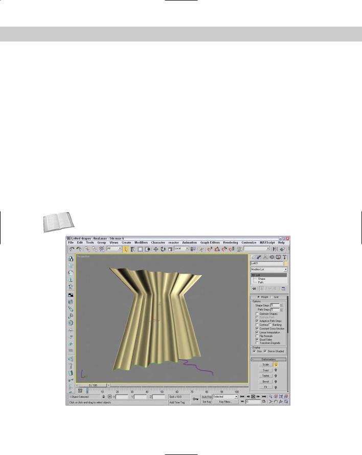
4.Use the Deformation functions to add more control to the drapes, such as tying them together as shown in Figure 17-29.
Loft objects versus Surface tools
You can create compound loft objects completely from 2D shape splines: One open spline is typically used as the Loft path, and other, closed splines are used as the cross sections. You can have several different cross sections, and these can change as you travel the path. Loft cross sections aren’t required to have the same number of vertices, and you can modify the scale and rotation of the cross sections with the Deformation options.
Cross- |
See Chapter 15, “Creating and Editing Patches,” for more detail on the surface tools. |
Reference |
|
Figure 17-29: Drapes that have been modeled using a Loft object