

- •Preface
- •About This Book
- •Acknowledgments
- •Contents at a Glance
- •Contents
- •Relaxing at the Beach
- •Dressing the Scene
- •Animating Motion
- •Rendering the Final Animation
- •Summary
- •The Interface Elements
- •Using the Menus
- •Using the Toolbars
- •Using the Viewports
- •Using the Command Panel
- •Using the Lower Interface Bar Controls
- •Interacting with the Interface
- •Getting Help
- •Summary
- •Understanding 3D Space
- •Using the Viewport Navigation Controls
- •Configuring the Viewports
- •Working with Viewport Backgrounds
- •Summary
- •Working with Max Scene Files
- •Setting File Preferences
- •Importing and Exporting
- •Referencing External Objects
- •Using the File Utilities
- •Accessing File Information
- •Summary
- •Customizing Modify and Utility Panel Buttons
- •Working with Custom Interfaces
- •Configuring Paths
- •Selecting System Units
- •Setting Preferences
- •Summary
- •Creating Primitive Objects
- •Exploring the Primitive Object Types
- •Summary
- •Selecting Objects
- •Setting Object Properties
- •Hiding and Freezing Objects
- •Using Layers
- •Summary
- •Cloning Objects
- •Understanding Cloning Options
- •Mirroring Objects
- •Cloning over Time
- •Spacing Cloned Objects
- •Creating Arrays of Objects
- •Summary
- •Working with Groups
- •Building Assemblies
- •Building Links between Objects
- •Displaying Links and Hierarchies
- •Working with Linked Objects
- •Summary
- •Using the Schematic View Window
- •Working with Hierarchies
- •Setting Schematic View Preferences
- •Using List Views
- •Summary
- •Working with the Transformation Tools
- •Using Pivot Points
- •Using the Align Commands
- •Using Grids
- •Using Snap Options
- •Summary
- •Exploring the Modifier Stack
- •Exploring Modifier Types
- •Summary
- •Exploring the Modeling Types
- •Working with Subobjects
- •Modeling Helpers
- •Summary
- •Drawing in 2D
- •Editing Splines
- •Using Spline Modifiers
- •Summary
- •Creating Editable Mesh and Poly Objects
- •Editing Mesh Objects
- •Editing Poly Objects
- •Using Mesh Editing Modifiers
- •Summary
- •Introducing Patch Grids
- •Editing Patches
- •Using Modifiers on Patch Objects
- •Summary
- •Creating NURBS Curves and Surfaces
- •Editing NURBS
- •Working with NURBS
- •Summary
- •Morphing Objects
- •Creating Conform Objects
- •Creating a ShapeMerge Object
- •Creating a Terrain Object
- •Using the Mesher Object
- •Working with BlobMesh Objects
- •Creating a Scatter Object
- •Creating Connect Objects
- •Modeling with Boolean Objects
- •Creating a Loft Object
- •Summary
- •Understanding the Various Particle Systems
- •Creating a Particle System
- •Using the Spray and Snow Particle Systems
- •Using the Super Spray Particle System
- •Using the Blizzard Particle System
- •Using the PArray Particle System
- •Using the PCloud Particle System
- •Using Particle System Maps
- •Controlling Particles with Particle Flow
- •Summary
- •Understanding Material Properties
- •Working with the Material Editor
- •Using the Material/Map Browser
- •Using the Material/Map Navigator
- •Summary
- •Using the Standard Material
- •Using Shading Types
- •Accessing Other Parameters
- •Using External Tools
- •Summary
- •Using Compound Materials
- •Using Raytrace Materials
- •Using the Matte/Shadow Material
- •Using the DirectX 9 Shader
- •Applying Multiple Materials
- •Material Modifiers
- •Summary
- •Understanding Maps
- •Understanding Material Map Types
- •Using the Maps Rollout
- •Using the Map Path Utility
- •Using Map Instances
- •Summary
- •Mapping Modifiers
- •Using the Unwrap UVW modifier
- •Summary
- •Working with Cameras
- •Setting Camera Parameters
- •Summary
- •Using the Camera Tracker Utility
- •Summary
- •Using Multi-Pass Cameras
- •Creating Multi-Pass Camera Effects
- •Summary
- •Understanding the Basics of Lighting
- •Getting to Know the Light Types
- •Creating and Positioning Light Objects
- •Viewing a Scene from a Light
- •Altering Light Parameters
- •Working with Photometric Lights
- •Using the Sunlight and Daylight Systems
- •Using Volume Lights
- •Summary
- •Selecting Advanced Lighting
- •Using Local Advanced Lighting Settings
- •Tutorial: Excluding objects from light tracing
- •Summary
- •Understanding Radiosity
- •Using Local and Global Advanced Lighting Settings
- •Working with Advanced Lighting Materials
- •Using Lighting Analysis
- •Summary
- •Using the Time Controls
- •Working with Keys
- •Using the Track Bar
- •Viewing and Editing Key Values
- •Using the Motion Panel
- •Using Ghosting
- •Animating Objects
- •Working with Previews
- •Wiring Parameters
- •Animation Modifiers
- •Summary
- •Understanding Controller Types
- •Assigning Controllers
- •Setting Default Controllers
- •Examining the Various Controllers
- •Summary
- •Working with Expressions in Spinners
- •Understanding the Expression Controller Interface
- •Understanding Expression Elements
- •Using Expression Controllers
- •Summary
- •Learning the Track View Interface
- •Working with Keys
- •Editing Time
- •Editing Curves
- •Filtering Tracks
- •Working with Controllers
- •Synchronizing to a Sound Track
- •Summary
- •Understanding Your Character
- •Building Bodies
- •Summary
- •Building a Bones System
- •Using the Bone Tools
- •Using the Skin Modifier
- •Summary
- •Creating Characters
- •Working with Characters
- •Using Character Animation Techniques
- •Summary
- •Forward versus Inverse Kinematics
- •Creating an Inverse Kinematics System
- •Using the Various Inverse Kinematics Methods
- •Summary
- •Creating and Binding Space Warps
- •Understanding Space Warp Types
- •Combining Particle Systems with Space Warps
- •Summary
- •Understanding Dynamics
- •Using Dynamic Objects
- •Defining Dynamic Material Properties
- •Using Dynamic Space Warps
- •Using the Dynamics Utility
- •Using the Flex Modifier
- •Summary
- •Using reactor
- •Using reactor Collections
- •Creating reactor Objects
- •Calculating and Previewing a Simulation
- •Constraining Objects
- •reactor Troubleshooting
- •Summary
- •Understanding the Max Renderers
- •Previewing with ActiveShade
- •Render Parameters
- •Rendering Preferences
- •Creating VUE Files
- •Using the Rendered Frame Window
- •Using the RAM Player
- •Reviewing the Render Types
- •Using Command-Line Rendering
- •Creating Panoramic Images
- •Getting Printer Help
- •Creating an Environment
- •Summary
- •Creating Atmospheric Effects
- •Using the Fire Effect
- •Using the Fog Effect
- •Summary
- •Using Render Elements
- •Adding Render Effects
- •Creating Lens Effects
- •Using Other Render Effects
- •Summary
- •Using Raytrace Materials
- •Using a Raytrace Map
- •Enabling mental ray
- •Summary
- •Understanding Network Rendering
- •Network Requirements
- •Setting up a Network Rendering System
- •Starting the Network Rendering System
- •Configuring the Network Manager and Servers
- •Logging Errors
- •Using the Monitor
- •Setting up Batch Rendering
- •Summary
- •Compositing with Photoshop
- •Video Editing with Premiere
- •Video Compositing with After Effects
- •Introducing Combustion
- •Using Other Compositing Solutions
- •Summary
- •Completing Post-Production with the Video Post Interface
- •Working with Sequences
- •Adding and Editing Events
- •Working with Ranges
- •Working with Lens Effects Filters
- •Summary
- •What Is MAXScript?
- •MAXScript Tools
- •Setting MAXScript Preferences
- •Types of Scripts
- •Writing Your Own MAXScripts
- •Learning the Visual MAXScript Editor Interface
- •Laying Out a Rollout
- •Summary
- •Working with Plug-Ins
- •Locating Plug-Ins
- •Summary
- •Low-Res Modeling
- •Using Channels
- •Using Vertex Colors
- •Rendering to a Texture
- •Summary
- •Max and Architecture
- •Using AEC Objects
- •Using Architectural materials
- •Summary
- •Tutorial: Creating Icy Geometry with BlobMesh
- •Tutorial: Using Caustic Photons to Create a Disco Ball
- •Summary
- •mental ray Rendering System
- •Particle Flow
- •reactor 2.0
- •Schematic View
- •BlobMesh
- •Spline and Patch Features
- •Import and Export
- •Shell Modifier
- •Vertex Paint and Channel Info
- •Architectural Primitives and Materials
- •Minor Improvements
- •Choosing an Operating System
- •Hardware Requirements
- •Installing 3ds max 6
- •Authorizing the Software
- •Setting the Display Driver
- •Updating Max
- •Moving Max to Another Computer
- •Using Keyboard Shortcuts
- •Using the Hotkey Map
- •Main Interface Shortcuts
- •Dialog Box Shortcuts
- •Miscellaneous Shortcuts
- •System Requirements
- •Using the CDs with Windows
- •What’s on the CDs
- •Troubleshooting
- •Index

408 Part III Modeling
To fix the normals on an imported mesh model, follow these steps:
1.Open the Hailing taxi man with incorrect normals.max file from the Chap 14 directory on the CD-ROM.
2.Select the problem object — the waist. Open the object hierarchy by clicking the plus sign to the left of the Editable Mesh object in the Modifier Stack, and select Element subobject mode.
3.In the Selection rollout, select the Show Normals option and set the Scale value to a small number such as 0.1.
The normals will be visible. Notice that some of them point outward and some of them point inward.
4.With the element subobject still selected, click the Unify button in the Surface Properties rollout and then click the Flip button until all normals are pointing outward.
This problem is now fixed, and the waist object is now a visible part of the mesh. The fixed mesh looks just like the original mesh without the ugly black shorts.
Editing Poly Objects
Editable Poly objects are created just like Editable Mesh objects, by converting, collapsing, or importing them. After an object has been converted to an Editable Poly object, you can work with its subobjects just like its meshy brother. Many of the buttons found in the Editable Mesh rollouts work exactly the same for Editable Poly objects. Only the differences are noted here.
Editable Poly subobject modes
The subobject modes for the Editable Poly are a little different. They include Vertex, Edge, Border, Polygon, and Element. The Border subobject mode selects all the edges around a polygon face, which may be more than three. The various subobject modes can be selected in the same manner as the Editable Mesh.
Before you can edit Poly subobjects, you must select them. To select a Subobject mode, select the hierarchy element under the Editable Poly object, click one of the subobject buttons in the Selection rollout, or use the keyboard shortcuts (1-5).
Many of the buttons for the Editable Poly include a small icon to the right of the button that opens a settings dialog box. These settings dialog boxes allow you to change the settings and immediately see the results in the viewports. The OK button applies the settings and closes the dialog box, and the Apply button applies the settings and leaves the dialog box open. These settings dialog boxes are included next to the Attach, MSmooth, and Tessellate buttons for all subobject modes and next to many of the subobject-specific buttons such as Extrude, Bevel, Outline, and Inset.
Another key difference for the Editable Poly objects is the location of their buttons. The Editable Mesh objects include all their buttons in a single Edit Geometry rollout, but the Editable Poly objects include all their common buttons in the Edit Geometry rollout and all subobject-specific buttons is a separate rollout named after the subobject mode, such as Edit Vertices or Edit Edges.
Chapter 14 Working with Meshes and Polys 409
Selection rollout
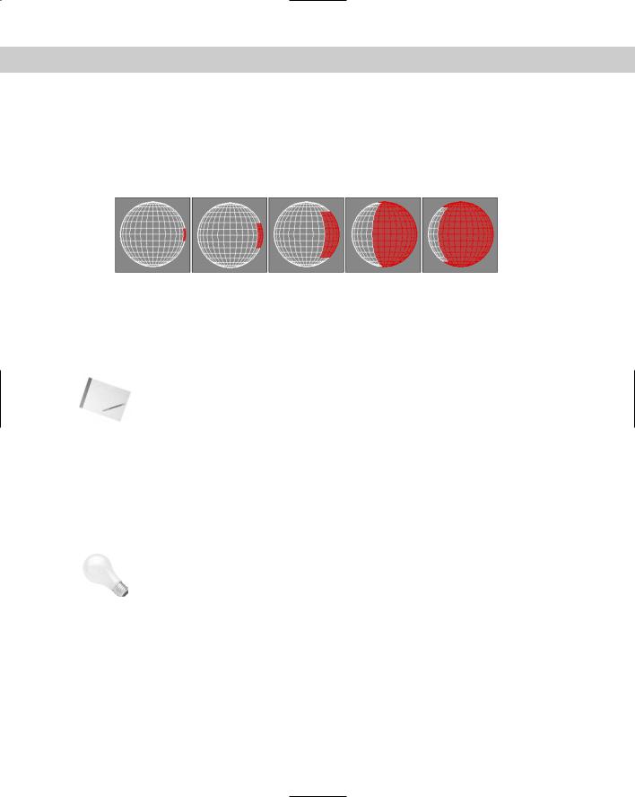
For Editable Poly objects, the Selection rollout includes the Subobject buttons, the By Vertex and Ignore Backfacing options, and four buttons. These buttons include Shrink, Grow, Ring, and Loop. Use the Grow button to increase the current selection around the perimeter of the current selection, as shown in Figure 14-12. Click the Shrink button to do the opposite.
Figure 14-12: Using the Grow button, you can increase the subobject selection.
The Ring and Loop buttons are available only in Edge and Border subobject modes. Use Ring and Loop to select all adjacent subobjects horizontally and vertically around the entire object. Ring selection looks for parallel edges, and Loop selection looks for all edges around an object that are aligned the same as the initial selection. For example, if you select a single
edge of a sphere, the Ring button selects all edges going around the sphere and the Loop button selects all edges in a line from the top to the bottom of the sphere.
Note |
For Editable Poly objects, the Hide Selected, Unhide All, Copy, and Paste buttons are located |
|
at the bottom of the Edit Geometry rollout. |
Edit Geometry rollout
The Edit Geometry rollout for Editable Poly objects includes all the general functions that apply to several subobject modes and that can be used with no subobject mode selected.
Repeat Last
The first button in the Edit Geometry rollout is the Repeat Last button. This button repeats the last subobject command. This button does not work on all features but is very convenient for certain actions.
Tip |
The tooltip for this button displays the last repeatable command. |
Enabling constraints
The Constraints drop-down list limits the movement of subobjects to a specified subobject. The available constraints are None, Edge, and Face. For example, if you select and move a vertex with the Edge constraint enabled, then the movement is constrained to the adjacent edges.
410 Part III Modeling
|
Create |
|
The Create button lets you create new subobjects, specifically polygons, by connecting iso- |
|
lated vertices and border vertices. When the cursor is over a valid vertex, it changes to a |
|
crosshair, and you can click to create a polygon edge from the last clicked point. If no vertices |
|
are available, you can Shift click to create one. This creates a vertex where you click. |
Tip |
As you create new polygons, the normal is determined by the direction in which you create |
|
the polygon using the right-hand rule. If you bend the fingers of your right hand in the direc- |
|
tion (clockwise or counterclockwise) that the vertices are clicked, then your thumb will point |
|
in the direction of the normal. If the normal is pointing away from you, then the backside of |
|
the polygon will be visible and the lighting could be off. |
QuickSlice
The QuickSlice button lets you click anywhere on an Editable Poly object where you want a slicing line to be located. You can then move the mouse, and the QuickSlice line rotates about the point you clicked on. When you click the mouse again, a new vertex is added at every place where the QuickSlice line intersects an object edge. This is a very convenient tool for slicing objects because the slice line follows the surface of the object, so you can see exactly where the slice will take place.
For the QuickSlice and Cut tools, you can enable the Full Interactivity option. With this option enabled, the slice lines are shown as you move the mouse about the surface. With Full Interactivity disabled, the resulting lines are shown only when the mouse is clicked.
Cut
For Editable Poly objects, the Cut button is interactive. If you click a polygon corner, the cut edge snaps to the corner, and a new edge extends from the corner to a nearby corner. As you move the mouse around, the edge moves until you click where the edge should end. If you click in the middle of an edge or face, then new edges appear to the nearest corner. This interactive cut method is much easier to use than the Editable Mesh object method.
MSmooth and Tessellate
Both the MSmooth and Tessellate buttons include new settings dialog boxes, as shown in Figure 14-13. The MSmooth setting for Smoothness rounds all the sharp edges of an object. Tessellation can be done using Edges or Faces, and the Tension setting controls how tight the adjacent faces are.
Figure 14-13: The Settings dialog boxes for the MSmooth and Tessellate buttons let you interactively set the Smoothness and Tension values.
Chapter 14 Working with Meshes and Polys 411
The MSmooth button can be used to smooth to the selected subobjects in the same way as the MeshSmooth modifier. This button can be used several times. The Smoothness value determines which vertices are used to smooth the object. The higher the value, the more vertices are included and the smoother the result. You can also select that the smoothing is separated by Smoothing Groups or by Materials.
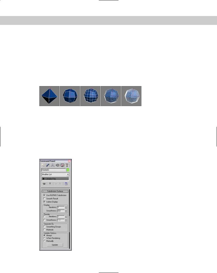
Tessellation is used to increase the density of the faces or edges. When modeling, you may want more details in a select area. This is where the tessellation command comes in. Tessellation can be applied to individual selected subobjects or to the entire object. Figure 14-14 shows a simple diamond-shaped hedra that has been MeshSmoothed using the MSmooth button and then tessellated three consecutive times.
Figure 14-14: Using MSmooth reduces the sharp edges, and tessellating adds more editable faces.
Subdivision Surface
Editable Poly objects include an extra rollout called Subdivision Surface that automatically smoothes the object when enabled. The Subdivision Surface rollout, shown in Figure 14-15, applies a smoothing algorithm known as NURMS, which stands for Non-Uniform Rational Mesh Smooth. It produces similar results to the MSmooth button, but offers control over how aggressive the smoothing is applied; the settings can be different for the viewports and the renderer.
Figure 14-15: The Subdivision Surface rollout includes controls for
NURMS subdivision.

412 Part III Modeling
To enable NURMS subdivision, you need to enable the Use NURMS Subdivision option. The Smooth Result option places all polygons into the same smoothing group and applies the MeshSmooth to the entire object. Applying NURMS with a high Iterations value results in a very dense mesh, but the Isoline Display option displays a simplified number of edges, making the object easier to work with. The process of smoothing adds many edges to the object, and the Isoline Display option displays only the isolines.
New |
The Isoline Display option is new to 3ds max 6. |
Feature |
|
The Iterations value determines how aggressive the smoothing is. The higher the Iterations value, the more time it takes to compute and the more complex the resulting object. The Smoothness value determines how sharp a corner must be before adding extra faces to smooth it. A value of 0 does not smooth any corners, and a maximum value of 1.0 smoothes all polygons.
The two check boxes in the Render section can be used to set the values differently for the Display and Render sections. If disabled, then both the viewports and the renderer use the same settings. The smoothing algorithm can be set to ignore smoothing across Smoothing Groups and Materials.
If the Show Cage option is enabled, an orange cage surrounds the NURMS object and shows the position of the polygon faces that exist if NURMS is disabled. This cage makes selecting the polygon faces easier.
Tutorial: Modeling a tooth
If you’ve ever had a root canal, then you know how much pain removing a tooth can cause. Luckily, modeling a tooth isn’t painful at all, as we see in this example.
To model a tooth using NURMS, follow these steps:
1.Select Create Standard Primitives Box, and drag in the Top viewport to create a Box object. Set its dimensions to 140×180×110 with Segments of 1×1×1. Then right-click and select Convert To Editable Poly from the pop-up quadmenu.
2.Click the Polygon icon in the Selection rollout to enable Polygon subobject mode. Then, select the Top viewport and press B to change it to the Bottom viewport. Then click the box’s bottom polygon in the Bottom viewport.
3.Click the Select and Scale button (R) and scale the bottom polygon 10%.
4.Drag over the entire object to select all polygons and click the Tessellate button once to divide the polygon into more polygons. Then select Edit Region Window (or click the Window/Crossing button in the main toolbar) to enable the Window selection method, and drag over the bottom of the Box object in the Left viewport to select just the bottom polygons. Click the Tessellate button again.
5.Select the Vertex subobject mode in the Selection rollout and, with the Ctrl key held down, select the vertices at the center of each quadrant. Then move these vertices downward in the Left viewport a distance about equal to the height of the Box.
Chapter 14 Working with Meshes and Polys 413
6.Select the Top viewport again and press T to change it back to the Top viewport. Select the single vertex in the center of the polygon with the Ignore Backfacing option enabled in the Selection rollout, and then drag it slightly downward in the Left viewport.
7.Disable the Ignore Backfacing option in the Selection rollout and select the entire second row of vertices in the Left viewport. With the Select and Scale tool, scale these vertices toward the center in the polygon in the Top viewport.
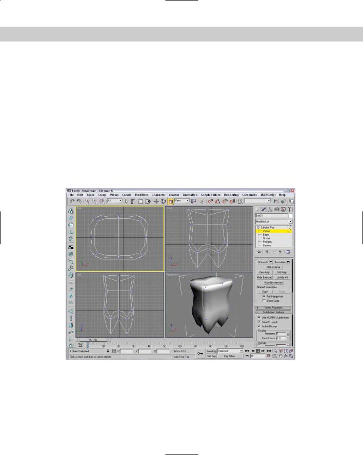
8.In the Subdivision Surface rollout, enable the Use NURMS Subdivision option and set the Iterations value to 1.
Figure 14-16 shows the completed tooth.
Editing vertices
When working with the Editable Poly objects, after you select a Vertex subobject mode (keyboard shortcut, 1) and select vertices, you can transform them using the transform buttons on the main toolbar. All vertex-specific commands are found within the Edit Vertices rollout.
Figure 14-16: The organic look for this tooth is accomplished with NURMS.
414 Part III Modeling
Remove
The Delete button for Editable Mesh objects lets you delete the selected vertices. However, the Remove button is similar to the Delete button, except that a hole isn’t left after the vertex is removed. The Remove button automatically adjusts the surrounding subobjects to maintain the mesh integrity.
Note |
You can still delete Editable Poly subobjects using the Delete key. |
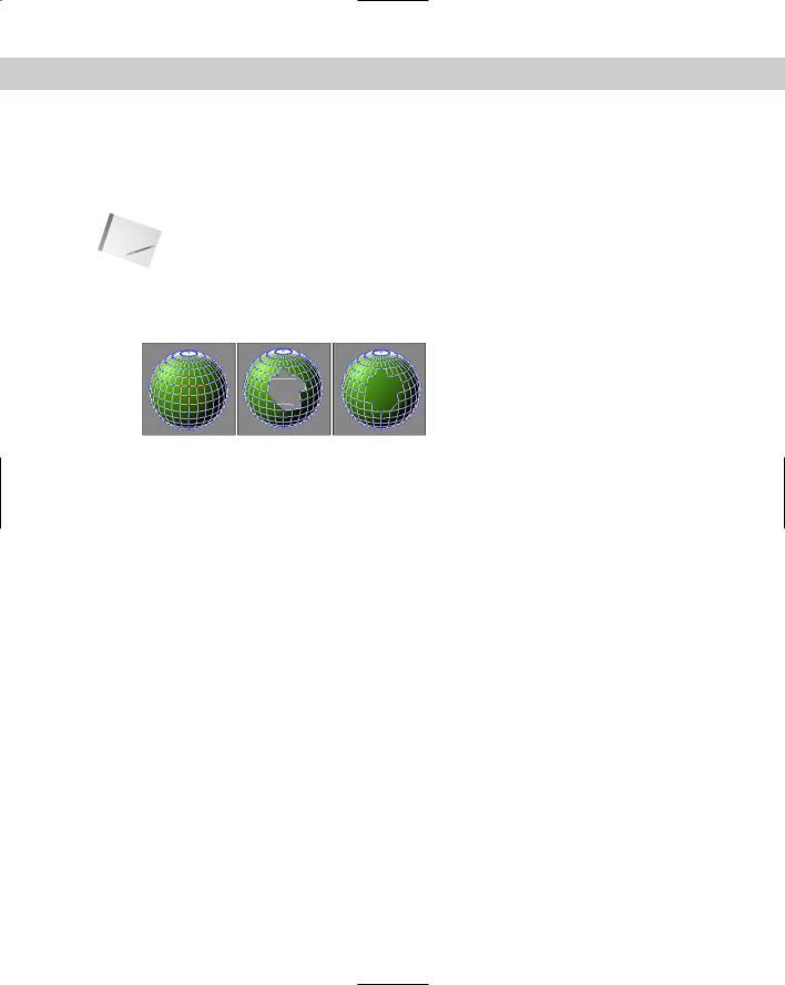
Figure 14-17 shows a sphere object with several vertex subobjects selected. The middle image is an Editable Mesh that used the Delete feature, and the right image is an Editable Poly that used the Remove feature.
Figure 14-17: Deleting vertices also deletes the adjoining faces and edges, but Remove maintains the mesh.
Extrude, Weld, and Chamfer
The Extrude, Weld, and Chamfer buttons all include a settings dialog box that lets you interactively see the results of different settings. The Extrude settings dialog box includes options for setting the Extrusion Height and the Extrusion Base Width. The Weld settings dialog box includes a weld Threshold value and displays the number of vertices before and after the welding process, which is very useful to check if a weld was successful. The Chamfer button, which is enabled in Vertex, Edge, and Border subobject modes, lets you cut the edge off a corner and replace it with a face. Using the settings dialog box, you can interactively specify a Chamfer Amount.
Connect
The Connect button can be used to add new edges to subobjects. In Vertex subobject mode, the button connects vertices on the opposite side of a face. In Edge and Border subobject mode, they make a settings dialog box available, which includes a setting to Connect Edge Segments. This value is the number of edge segments to use to add between the selected edges or borders.
Remove Unused Map Vertices
The Remove Unused Map Vertices button removes any leftover mapping vertices from the object.
Weight
The Weight settings control the amount of pull that a vertex has when NURMS subdivision or a MeshSmooth modifier is used. The higher the Weight value, the more resistant a vertex is to smoothing.

Chapter 14 Working with Meshes and Polys 415
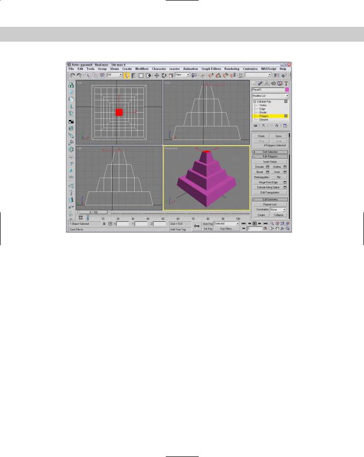
Tutorial: Building a beveled pyramid
The Egyptians were pyramid masters, but modeling a pyramid is too easy because it is one of the primitives. Instead, we look to the Aztec civilization for a pyramid example that has several flat terraces on the way to the top. This gives you a chance to practice working with an Editable Poly object.
To create a multi-stage pyramid from an Editable Poly object, follow these steps:
1.Select Create Standard Primitives Plane, and drag in the Top viewport to create a Box object. Set its dimensions to 100×100 with Segments of 1×1. Then right-click and select Convert To Editable Poly from the pop-up quadmenu.
2.In the Selection rollout of the Modify panel, click the Polygon subobject button and enable the Ignore Backfacing option. Then click the object in the Top viewport to select the topmost polygon.
Notice at the bottom of the Selection rollout that only one polygon is listed as being selected.
3.In the Edit Polygon rollout, click the Bevel settings button and enter a Height value of 20 and an Outline Amount value of –5. Then click OK to close the dialog box.
This makes the top polygon smaller than the bottom polygon.
4.Click the Tessellate button three times.
This divides the top polygon into 64 separate polygons.
5.While still in Polygon subobject mode, hold down the Ctrl key, click the four middle polygons, and then click the Grow button in the Selection rollout until all but the outside row of polygons in the Top viewport are selected.
The bottom of the Selection rollout lists 36 polygons selected.
6.Click the Bevel settings button in the Edit Geometry rollout again, enter a value of 20 for the Height value and –5 for the Outline Amount value, and click OK.
7.Repeat Steps 5 and 6 two more times to complete the pyramid.
Figure 14-18 shows the completed pyramid.
Editing edges and borders
Edges are the lines that run between two vertices. All buttons that work with edges are located in the Edit Edges rollout. Most include the same functionality as those covered in the Editable Mesh object.
Editable Poly objects do not need the Face subobject because they support polygon faces. Instead, they have a Border subobject. The Border subobject is polygons without any face and edges on all sides that are actually holes within the geometry.
416 Part III Modeling
Figure 14-18: This pyramid was created from an Editable Poly object.
Insert Vertex
The Insert Vertex button lets you add a new vertex anywhere along an edge. The cursor changes to crosshairs when it is over an edge. Click to create a vertex. When in Edge, Border, Polygon, or Element subobject mode, this button also makes vertices visible.
Edit Triangulation
For the Editable Poly object, the Edge, Border, Polygon, and Element subobjects include the Edit Triangulation button. The Edit Triangulation button lets you change the internal edges of the polygon by dragging from one vertex to another. When this button is clicked, all hidden edges appear. To edit the hidden edges, just click a vertex and then click again where you want the hidden edge to go.
Editing Polygon and Element subobjects
Like the other subobject modes, Editable Polys can be edited at the polygon and element subobject level. The buttons for these modes are found in the Edit Polygons and Edit Elements rollouts.
Outline and Inset
The Outline button offsets the selected polygon a specified amount. This increases the size of the selected polygon or element. The Inset button creates another polygon set within the selected polygon and connects their edges. For both these buttons, a Settings dialog box is available that includes the Outline or Inset Amount values.
Chapter 14 Working with Meshes and Polys 417
Retriangulate and Flip
The Retriangulate button automatically computes all the internal edges for you, and Flip Normals flips the normal vectors for the selected subobjects. The Flip button is available only in Polygon and Element subobject modes.
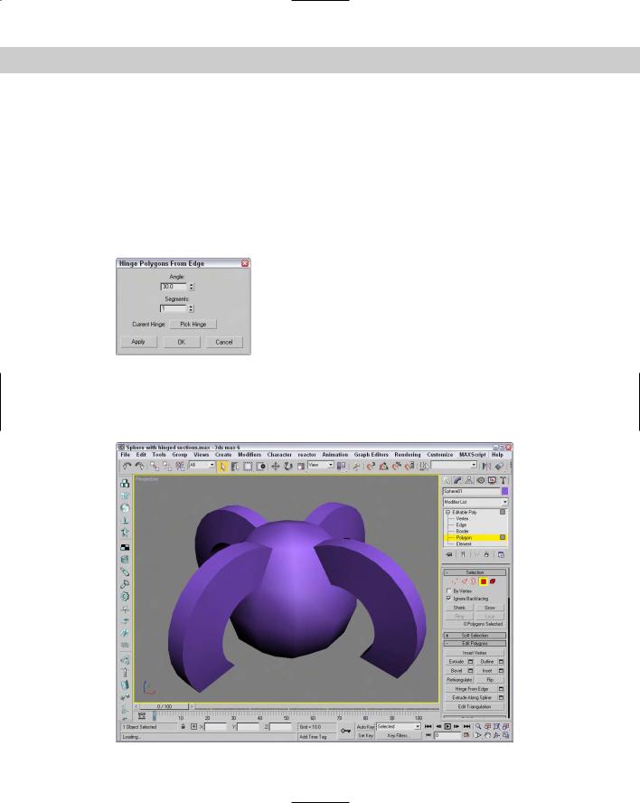
Hinge From Edge
The Hinge From Edge button rotates a selected polygon as if one of its edges were a hinge. The angle of the hinge depends on the distance that you drag with the mouse, or you can use the available settings dialog box. In the settings dialog box, shown in Figure 14-19, you can specify an Angle value and the number of segments to use for the hinged section.
Figure 14-19: The Hinge Polygons From Edge dialog box lets you select a hinge.
By default, one of the polygon’s edges will be used as the hinge about which the section rotates, but in the settings dialog box, you can click the Pick Hinge button and select an edge (which doesn’t need to be attached to the polygon). Figure 14-20 shows a sphere primitive with four polygon faces that have been hinged around an edge at the sphere’s center.
Figure 14-20: Several polygon faces in the sphere have been extruded along a hinge.

418 Part III Modeling
Extrude Along Spline
The Extrude Along Spline button can be used to extrude a selected polygon along the spline path. The settings dialog box, shown in Figure 14-21, includes a Pick Spline button that you can use to select the spline to use. You can also specify the number of segments, the Taper Amount and Curve, and a Twist value. You also have an option to Align the extrusion to the face normal or to rotate about the normal.
Figure 14-21: The Extrude Polygons
Along Spline settings dialog box
Tutorial: Building an octopus
The one thing about an octopus that makes it unique is the eight legs that it has (actually spiders also have eight legs, but work with me here). Creating these legs can be easily accomplished with the Extrude Along Spline feature.
To create an octopus using the Extrude Along Spline feature, follow these steps:
1.Open the Octopus.max file from the Chap 14 directory on the CD-ROM.
This file includes the base of an octopus created from a squashed sphere primitive that has been converted to an Editable Poly. Eight splines surround the object.
2.Select the octopus object to automatically open the Modify panel. In the Selection rollout, click the Polygon subobject button (keyboard shortcut, 4) and enable the Ignore Backfacing option.
3.Right-click the Perspective viewport title, and select the Edged Faces option from the pop-up menu.
This makes the polygons easier to see.
4.Click a single face object at the base of the sphere object, and click the Extrude Along Spline settings dialog box button to open the Extrude Polygons Along Spline dialog box.
5.Click the Pick Spline button, and select the spline to the side of the face. Set the Segments to 6 and the Taper Amount to –1.0, and click the OK button. Make sure that the Align to Face Normal option isn’t selected.
6.Repeat the last two steps for each spline surrounding the octopus.
7.In the Subdivisions Surface rollout, enable the Use NURMS Subdivision option and set the Display Iterations value to 2 to smooth the entire octopus.
Figure 14-22 shows the resulting octopus.