

- •Preface
- •About This Book
- •Acknowledgments
- •Contents at a Glance
- •Contents
- •Relaxing at the Beach
- •Dressing the Scene
- •Animating Motion
- •Rendering the Final Animation
- •Summary
- •The Interface Elements
- •Using the Menus
- •Using the Toolbars
- •Using the Viewports
- •Using the Command Panel
- •Using the Lower Interface Bar Controls
- •Interacting with the Interface
- •Getting Help
- •Summary
- •Understanding 3D Space
- •Using the Viewport Navigation Controls
- •Configuring the Viewports
- •Working with Viewport Backgrounds
- •Summary
- •Working with Max Scene Files
- •Setting File Preferences
- •Importing and Exporting
- •Referencing External Objects
- •Using the File Utilities
- •Accessing File Information
- •Summary
- •Customizing Modify and Utility Panel Buttons
- •Working with Custom Interfaces
- •Configuring Paths
- •Selecting System Units
- •Setting Preferences
- •Summary
- •Creating Primitive Objects
- •Exploring the Primitive Object Types
- •Summary
- •Selecting Objects
- •Setting Object Properties
- •Hiding and Freezing Objects
- •Using Layers
- •Summary
- •Cloning Objects
- •Understanding Cloning Options
- •Mirroring Objects
- •Cloning over Time
- •Spacing Cloned Objects
- •Creating Arrays of Objects
- •Summary
- •Working with Groups
- •Building Assemblies
- •Building Links between Objects
- •Displaying Links and Hierarchies
- •Working with Linked Objects
- •Summary
- •Using the Schematic View Window
- •Working with Hierarchies
- •Setting Schematic View Preferences
- •Using List Views
- •Summary
- •Working with the Transformation Tools
- •Using Pivot Points
- •Using the Align Commands
- •Using Grids
- •Using Snap Options
- •Summary
- •Exploring the Modifier Stack
- •Exploring Modifier Types
- •Summary
- •Exploring the Modeling Types
- •Working with Subobjects
- •Modeling Helpers
- •Summary
- •Drawing in 2D
- •Editing Splines
- •Using Spline Modifiers
- •Summary
- •Creating Editable Mesh and Poly Objects
- •Editing Mesh Objects
- •Editing Poly Objects
- •Using Mesh Editing Modifiers
- •Summary
- •Introducing Patch Grids
- •Editing Patches
- •Using Modifiers on Patch Objects
- •Summary
- •Creating NURBS Curves and Surfaces
- •Editing NURBS
- •Working with NURBS
- •Summary
- •Morphing Objects
- •Creating Conform Objects
- •Creating a ShapeMerge Object
- •Creating a Terrain Object
- •Using the Mesher Object
- •Working with BlobMesh Objects
- •Creating a Scatter Object
- •Creating Connect Objects
- •Modeling with Boolean Objects
- •Creating a Loft Object
- •Summary
- •Understanding the Various Particle Systems
- •Creating a Particle System
- •Using the Spray and Snow Particle Systems
- •Using the Super Spray Particle System
- •Using the Blizzard Particle System
- •Using the PArray Particle System
- •Using the PCloud Particle System
- •Using Particle System Maps
- •Controlling Particles with Particle Flow
- •Summary
- •Understanding Material Properties
- •Working with the Material Editor
- •Using the Material/Map Browser
- •Using the Material/Map Navigator
- •Summary
- •Using the Standard Material
- •Using Shading Types
- •Accessing Other Parameters
- •Using External Tools
- •Summary
- •Using Compound Materials
- •Using Raytrace Materials
- •Using the Matte/Shadow Material
- •Using the DirectX 9 Shader
- •Applying Multiple Materials
- •Material Modifiers
- •Summary
- •Understanding Maps
- •Understanding Material Map Types
- •Using the Maps Rollout
- •Using the Map Path Utility
- •Using Map Instances
- •Summary
- •Mapping Modifiers
- •Using the Unwrap UVW modifier
- •Summary
- •Working with Cameras
- •Setting Camera Parameters
- •Summary
- •Using the Camera Tracker Utility
- •Summary
- •Using Multi-Pass Cameras
- •Creating Multi-Pass Camera Effects
- •Summary
- •Understanding the Basics of Lighting
- •Getting to Know the Light Types
- •Creating and Positioning Light Objects
- •Viewing a Scene from a Light
- •Altering Light Parameters
- •Working with Photometric Lights
- •Using the Sunlight and Daylight Systems
- •Using Volume Lights
- •Summary
- •Selecting Advanced Lighting
- •Using Local Advanced Lighting Settings
- •Tutorial: Excluding objects from light tracing
- •Summary
- •Understanding Radiosity
- •Using Local and Global Advanced Lighting Settings
- •Working with Advanced Lighting Materials
- •Using Lighting Analysis
- •Summary
- •Using the Time Controls
- •Working with Keys
- •Using the Track Bar
- •Viewing and Editing Key Values
- •Using the Motion Panel
- •Using Ghosting
- •Animating Objects
- •Working with Previews
- •Wiring Parameters
- •Animation Modifiers
- •Summary
- •Understanding Controller Types
- •Assigning Controllers
- •Setting Default Controllers
- •Examining the Various Controllers
- •Summary
- •Working with Expressions in Spinners
- •Understanding the Expression Controller Interface
- •Understanding Expression Elements
- •Using Expression Controllers
- •Summary
- •Learning the Track View Interface
- •Working with Keys
- •Editing Time
- •Editing Curves
- •Filtering Tracks
- •Working with Controllers
- •Synchronizing to a Sound Track
- •Summary
- •Understanding Your Character
- •Building Bodies
- •Summary
- •Building a Bones System
- •Using the Bone Tools
- •Using the Skin Modifier
- •Summary
- •Creating Characters
- •Working with Characters
- •Using Character Animation Techniques
- •Summary
- •Forward versus Inverse Kinematics
- •Creating an Inverse Kinematics System
- •Using the Various Inverse Kinematics Methods
- •Summary
- •Creating and Binding Space Warps
- •Understanding Space Warp Types
- •Combining Particle Systems with Space Warps
- •Summary
- •Understanding Dynamics
- •Using Dynamic Objects
- •Defining Dynamic Material Properties
- •Using Dynamic Space Warps
- •Using the Dynamics Utility
- •Using the Flex Modifier
- •Summary
- •Using reactor
- •Using reactor Collections
- •Creating reactor Objects
- •Calculating and Previewing a Simulation
- •Constraining Objects
- •reactor Troubleshooting
- •Summary
- •Understanding the Max Renderers
- •Previewing with ActiveShade
- •Render Parameters
- •Rendering Preferences
- •Creating VUE Files
- •Using the Rendered Frame Window
- •Using the RAM Player
- •Reviewing the Render Types
- •Using Command-Line Rendering
- •Creating Panoramic Images
- •Getting Printer Help
- •Creating an Environment
- •Summary
- •Creating Atmospheric Effects
- •Using the Fire Effect
- •Using the Fog Effect
- •Summary
- •Using Render Elements
- •Adding Render Effects
- •Creating Lens Effects
- •Using Other Render Effects
- •Summary
- •Using Raytrace Materials
- •Using a Raytrace Map
- •Enabling mental ray
- •Summary
- •Understanding Network Rendering
- •Network Requirements
- •Setting up a Network Rendering System
- •Starting the Network Rendering System
- •Configuring the Network Manager and Servers
- •Logging Errors
- •Using the Monitor
- •Setting up Batch Rendering
- •Summary
- •Compositing with Photoshop
- •Video Editing with Premiere
- •Video Compositing with After Effects
- •Introducing Combustion
- •Using Other Compositing Solutions
- •Summary
- •Completing Post-Production with the Video Post Interface
- •Working with Sequences
- •Adding and Editing Events
- •Working with Ranges
- •Working with Lens Effects Filters
- •Summary
- •What Is MAXScript?
- •MAXScript Tools
- •Setting MAXScript Preferences
- •Types of Scripts
- •Writing Your Own MAXScripts
- •Learning the Visual MAXScript Editor Interface
- •Laying Out a Rollout
- •Summary
- •Working with Plug-Ins
- •Locating Plug-Ins
- •Summary
- •Low-Res Modeling
- •Using Channels
- •Using Vertex Colors
- •Rendering to a Texture
- •Summary
- •Max and Architecture
- •Using AEC Objects
- •Using Architectural materials
- •Summary
- •Tutorial: Creating Icy Geometry with BlobMesh
- •Tutorial: Using Caustic Photons to Create a Disco Ball
- •Summary
- •mental ray Rendering System
- •Particle Flow
- •reactor 2.0
- •Schematic View
- •BlobMesh
- •Spline and Patch Features
- •Import and Export
- •Shell Modifier
- •Vertex Paint and Channel Info
- •Architectural Primitives and Materials
- •Minor Improvements
- •Choosing an Operating System
- •Hardware Requirements
- •Installing 3ds max 6
- •Authorizing the Software
- •Setting the Display Driver
- •Updating Max
- •Moving Max to Another Computer
- •Using Keyboard Shortcuts
- •Using the Hotkey Map
- •Main Interface Shortcuts
- •Dialog Box Shortcuts
- •Miscellaneous Shortcuts
- •System Requirements
- •Using the CDs with Windows
- •What’s on the CDs
- •Troubleshooting
- •Index
Chapter 44 Raytracing and mental ray 1047
Y-axis Tiling value to 20 in the Coordinates rollout. Then click the Go to Parent button, and in the Blinn Basic Parameters rollout, increase the Specular Level to 75. Name the material Tabletop, and drag the material to the tabletop.
6.In a graphics program like Adobe Photoshop, create and save a 200×200 image with some repeating colored vertical stripes that can be used as wallpaper. Select the fifth sample slot, and click the map button to the right of the Diffuse color. In the Material/ Map Browser, double-click the Bitmap selection. A File dialog box loads, in which you can locate the wallpaper image. In the Coordinates rollout, set the U-coordinate Tiling value to 100 and drag the material to the wall plane object.
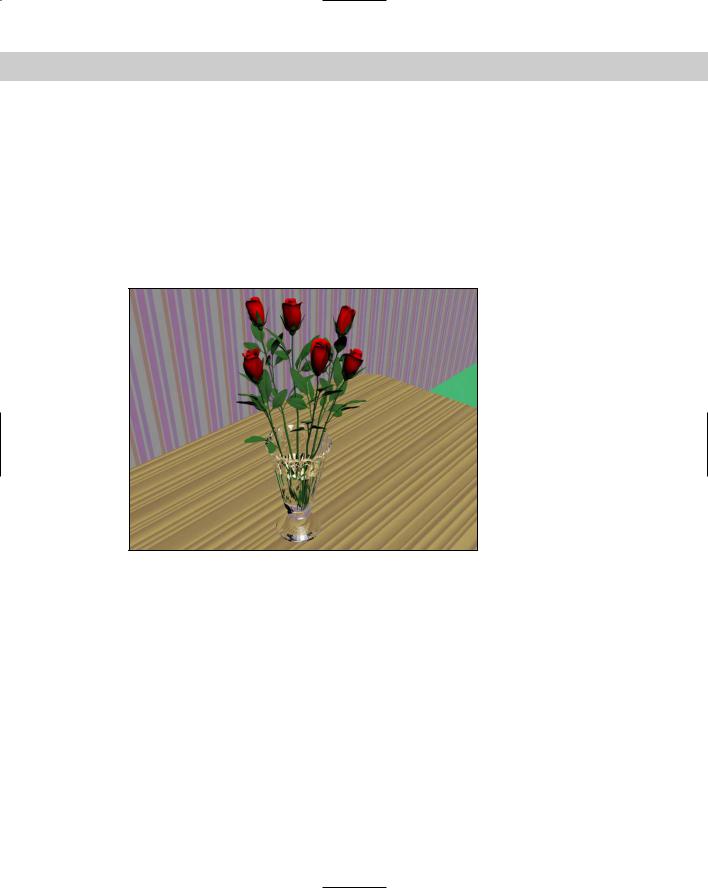
Figure 44-10 shows the rendered image.
Figure 44-10: A rendered image with raytrace materials applied to the vase and table
Using a Raytrace Map
The raytrace map is an alternative to the raytrace material discussed previously and, as a map, can be used in places where the raytrace material cannot.
The raytrace map includes several similar rollouts and several unique rollouts. In the Raytracer Parameters rollout, the Local Options section lets you select to Enable Raytracing, enable Raytrace Atmospherics, Enable Self Reflect/Refract, and use Reflect/Refract Material IDs. The Trace Mode determines how the rays are cast through the scene. Options include Auto Detect, Reflection, and Refraction. You can also use the Environment Settings or specify a color or map to use for the Background.

1048 Part X Rendering
Setting Raytrace parameters
The Local Exclude button opens the Exclude/Include dialog box where you can select which items to include or exclude in the raytracing calculations. The Raytracing Antialiasing dropdown list is enabled using the Global Raytracing Settings dialog box.
Note |
You set global raytracing options using the Rendering Raytracer Settings menu command. |
The Attenuation rollout lets you select from one of several Falloff Types. The options include Linear, Inverse Square, Exponential, and Custom Falloff. You can also set values for the Start and End distances. The Custom Falloff type lets you set a graph by adjusting Near, Far, and two Control values.
The Basic Material Extensions rollout lets you set the Reflectivity/Opacity Map and its strength. You can also set a Basic Tinting color or map. The Refractive Material Extensions rollout includes settings for specifying the Color Density (Filter color) and Fog.
Tutorial: Raytracing a wine glass
Raytracing complex scenes requires some serious processor power because each light ray that is being traced can bounce off many different objects multiple times. By applying a raytrace map to a single object, you can dramatically decrease the render time while still maintaining a quality look.
To apply a raytrace map to the glass in this scene, follow these steps:
1.Open the Table setting.max file from the Chap 44 directory on the CD-ROM.
This file includes all the meshes used for a table setting. These models were provided courtesy of Zygote Media. The materials for everything except the wine glass are already included, assigned, and visible in the Material Editor in the first four sample slots.
2.Choose Rendering Material Editor (or press the M key) to open the Material Editor.
3.Select the fifth sample slot, name the material Wine Glass, and click the map button to the right of the Diffuse color swatch to open the Material/Map Browser. In the Material/ Map Browser, double-click the raytrace map.
4.In the Raytracer Parameters rollout, select the Refraction Trace Mode option and select the Black color swatch option in the Background section.
5.Drag the “Wine Glass” material to the wine glass object in the viewport to apply the material to the object.
6.In the Material Editor, drag the “Wine Glass” material to the sixth sample slot and select the Diffuse map. Then change the Background color to White, and drag the new material to the drinking glass positioned next to the wine glass. In the Assigning Material dialog box that opens, name this material Drinking glass.
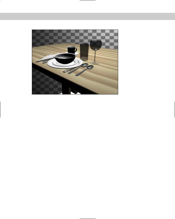
Figure 44-11 shows a place setting created by Zygote Media that includes a wine glass with a raytrace map applied.
Chapter 44 Raytracing and mental ray 1049
Figure 44-11: You can use the raytrace map to raytrace only select objects.
Enabling mental ray
If you’re accustomed to using the Default Scanline Renderer and you’re wondering if the mental ray rendering engine is good for you, the answer if yes. Actually, you should try a couple of test renderings first and play with the different settings, but in working with mental ray, I’ve been amazed at its results.
As a raytracing renderer, mental ray is very fast. It also includes support for global illumination without having to enable the Advanced Lighting settings. In addition, mental ray can use all of Max’s existing materials without having to use a limited specialized material like the Raytrace material. Each material has a new rollout that lets you specialize mental ray settings.
mental ray also includes native support for Area Lights, Shaders, Depth of Field, and Motion Blur. It also includes some specialized lights that offer functionality, such as caustics, that is unavailable in the Scanline Renderer.
To choose mental ray as the renderer for your scene, simply select it from the list of available renderers in the Assign Renderer rollout of the Common panel of the Render Scene dialog box. You can set a different renderer for Production, the Material Editor, and the ActiveShade viewer. To make mental ray your default renderer, click the Save as Defaults button in this rollout.
Once selected as your Production renderer, you don’t need to modify any other settings for the renderer to work. The mental ray settings in the Material Editor, Lights category, and Object Properties dialog box enable additional features that mental ray can take advantage of, but they aren’t required to render the scene.
1050 Part X Rendering
mental ray preferences
In the Preference Settings dialog box is a panel of global mental ray settings, shown in Figure 44-12. In this panel, you can select to Enable mental ray Extensions. These extensions add some additional controls to several of the various mental ray panels.
Figure 44-12: The Preference Settings dialog box includes a panel of mental ray settings.
When the Scanline Renderer renders a scene, it progresses one line of pixels at a time down the image, but mental ray renders the image by breaking it up into blocks and rendering a block at a time. The Show Brackets on Current Buckets option displays white brackets around the current block as the image renders. You can also select to clear the frame before rendering.
The Messages section lets you specify which messages are displayed as the file renders. Options include Errors, Log Information, Log Progress, Debug Messages, and whether to write this information to a file.
Understanding Shaders
A Shader is an algorithm that defines how light is reflected through a scene. Surface Shaders determine the light properties that are reflected off the surface of an object; Atmospheric Shaders change the light properties as they move through a volume. Shaders can be programmed and applied to objects and scenes, and renderers like mental ray render the scene based on these shaders.

Chapter 44 Raytracing and mental ray 1051
mental ray materials and shaders
With the mental ray renderer selected, all materials include an additional rollout labeled mental ray Connection. This rollout, shown in Figure 44-13, is available only if the mental ray extensions are enabled in the mental ray panel of the Preference Settings dialog box. They
let you override the existing shaders used by the Scanline renderer and enable additional shaders that the mental ray renderer will use.
Figure 44-13: The mental ray Connection rollout in the Material Editor lets you override the default shaders.
The lock icons to the right of the shader buttons are the default shaders used by the Scanline renderer. To select a new shader, simply unlock these shaders by clicking the lock button.
If a material is opaque, you can speed up the rendering process by flagging the material as Opaque using the option at the bottom of the rollout.
If you want to get direct access to the shaders used by mental ray, use the mental ray material type, which presents all the shaders listed in the mental ray Connection rollout.
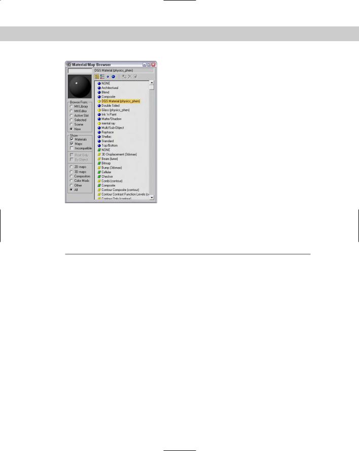
In addition to modifying the default materials to take advantage of mental ray, a number of mental ray materials and maps (shaders) are available from the Material/Map Browser, shown in Figure 44-14. These materials and maps show up only if the mental ray renderer is the assigned renderer and are marked in the Material/Map Browser with a yellow icon. All the mental ray materials and maps are split into different libraries, which are displayed in parentheses beside their name.
Note |
Several materials and maps in the Material/Map Browser do not work with mental ray. These |
|
items are marked with a gray icon. You can hide all these items by disabling the |
|
Incompatible option in the Show section of the Material/Map Browser. |
1052 Part X Rendering
Figure 44-14: The Material/Map Browser includes many additional mental ray materials and maps.
A complete list of the mental ray materials and maps is listed in Table 44-1.
|
Table 44-1: mental ray Materials and Maps |
|
|
Type |
List |
|
|
mental ray materials |
DGS Material, Glass, mental ray |
mental ray maps |
3D Displacement, Beam, Bump, Combi, Contour Composite, Contour Contrast |
|
Function Levels, Contour Only, Contour PS, Contour Store Function, Curvature, |
|
Depth Fade, DGS Material, DGS Material Photon, Distortion, Edge, Edge |
|
Shadow, Environment, Façade, Factor Color, Glass, Glow, Landscape, Layer |
|
Thinner, Light Infinite, Light Point, Light Spot, Material to Shader, Metal, Mist, |
|
Night, Ocean, Opacity, Parti Volume, Parti Volume Photon, Photon Basic, |
|
Reflect, Refract, Shader List, Shadow Transparency, Simple, Stain, Submerge, |
|
Texture Remap, Texture Rotate, Texture Wave, Translucency, Transmat, |
|
Transmat Photon, Transparency, Two-Sided, UV Coordinate, UV Generator, |
|
Water Surface, Water Surface Shadow, Wet-Dry Mixer, Width from Color, Width |
|
From Light, Width form Light Direction, Wrap Around, XYZ Coordinate, XYZ |
|
Generator |
|
|
Chapter 44 Raytracing and mental ray 1053
mental ray lights and shadows
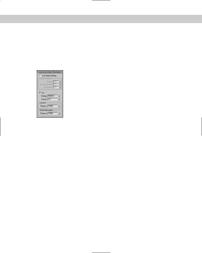
If you look in the Lights category of the Create Lights Standard Lights menu, you see two mental ray specific lights: mental ray Area Omni and mental ray Area Point. These area lights spread light from a defined area in the Area Light Parameters rollout. By default, all mental lights use the Global Settings for their illumination values, but by using the mental ray Indirect Illumination rollout, shown in Figure 44-15, found in the Modify panel, you can override the global settings for the selected light.
Figure 44-15: The mental ray Indirect Illumination rollout lets you define the light settings for individual lights.
Enabling mental ray Shadow Maps
In the Shadows drop-down list is an option to enable mental ray Shadow Maps. These shadow maps are more accurate than normal shadow maps.
Understanding Caustics and Photons
Light properties for the mental ray renderer include four unique properties: Energy, Decay, Caustic Photons, and Global Illumination (GI) Photons. Before explaining these properties, you need to understand what caustics and photons are.
Caustics are those strange glowing lines that you see at the bottom of an indoor swimming pool caused by the light refracting through the water. Caustics are common in nature, and now with mental ray, you can add these effects to your scenes. Photons are small bundles of light energy, and like the raytracing rays, they are emitted from a light source with a given amount of energy. This energy is lost as the photon travels and as it hits objects in the scene.
The Energy value is the amount of light energy that each photon starts out with, and the Decay value specifies how quickly that energy dissipates. The number of Caustic and GI Photons determines the resulting accuracy of the lighting. More photons yield a better solution, but the greater number also increases the render time substantially.
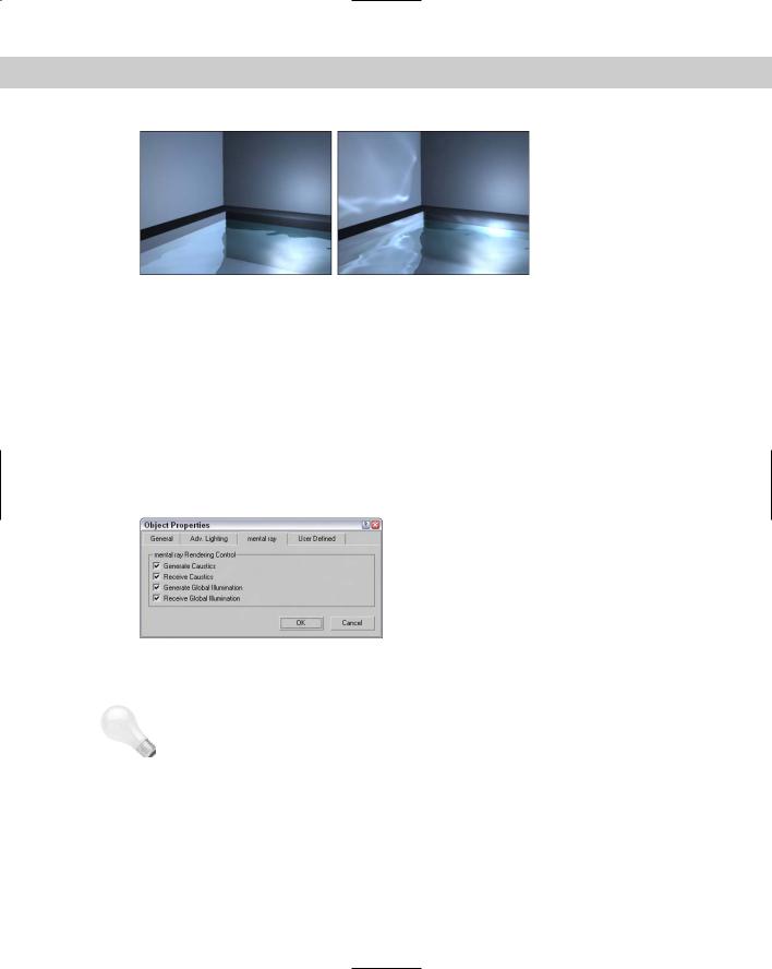
Figure 44-16 shows a swimming pool with caustics glowing on the side of the wall. The left image shows the pool scene with caustics disabled, and the right image shows them enabled.
1054 Part X Rendering
Figure 44-16: This indoor swimming pool scene is rendered without caustics (left) and with caustics (right).
In order to get caustics to work in your scene, you need to add a Raytrace, Flat Mirror, or Reflect/Refract map to the Reflection map channel for the material that you want to generate caustics.
Enabling caustics and global illumination for objects
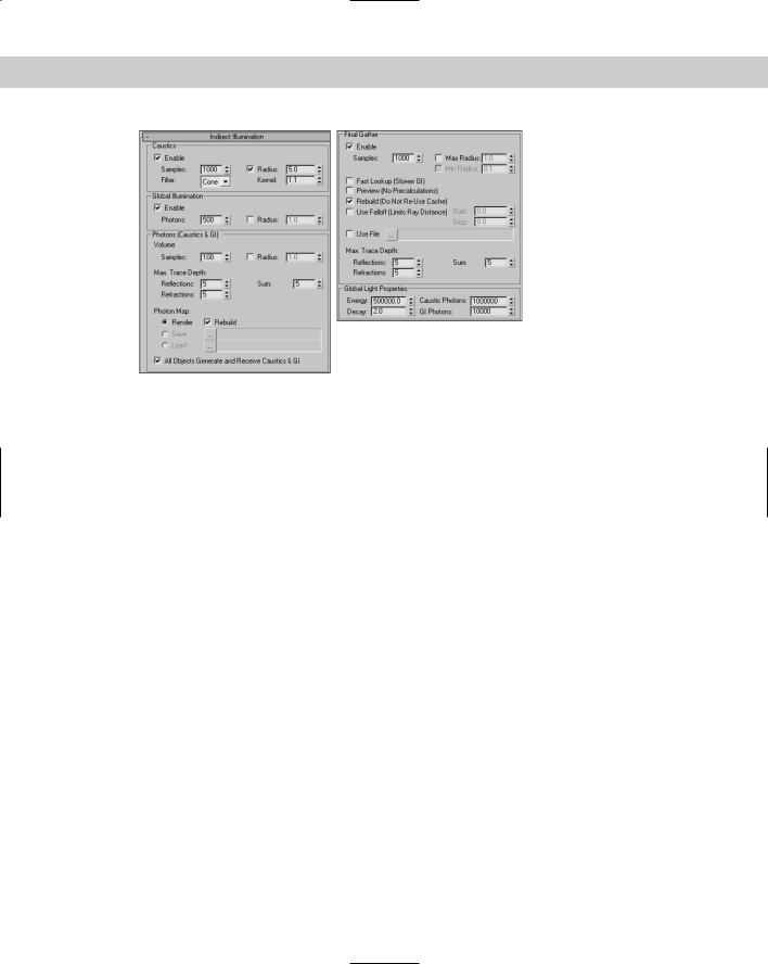
Another “gotcha” when dealing with caustics and global illumination is that each object can be specified to generate and/or receive caustics and global illumination. These settings are found in the mental ray panel of the Object Properties dialog box, shown in Figure 44-17. This dialog box can be opened using the Edit Properties menu command. If your scene isn’t generating caustics and you can’t figure out why, check this dialog box, because the Generate Caustics option is disabled by default.
|
Figure 44-17: The Object Properties dialog |
|
box includes options for generating and |
|
receiving caustics and global illumination. |
Tip |
The Indirect Illumination panel of the Render Scene dialog box includes an option that can |
|
be used to cause All Objects to Generate and Receive Caustics and GI. Enabling this option |
|
enables these options for all objects regardless of their Object Properties settings. |
|
Controlling Indirect Illumination |
In addition to the light settings, you can set many of the properties that control how caustics, global illumination, and final gather are computed in the Indirect Illumination panel of the Render Scene dialog box, shown in Figure 44-18.
Chapter 44 Raytracing and mental ray 1055
Figure 44-18: The Indirect Illumination panel includes settings for caustics, global illumination, and final gather.
For caustics and for global illumination, the Samples (or the Photons value for global illumination) value determines how the caustic photons are blended. A higher Sample value results in more blending and softer edges. The Radius value sets the size of each photon. This value is set automatically depending on the size of the scene. However, you can enable the Radius value and enter a new value manually.
The Volume setting is used by Volume material shaders to set the photon’s size. The Max Trace Depth settings determine the maximum number of reflections and refractions that a photon can take before it is ignored.
Photon maps can take a while to generate for a complicated scene, but once computed, they can be saved and reloaded. These files are saved using the .PMAP extension.
Final gather sends out rays to a scene that has computed caustics and global illumination already and computes the light at that location. All these rays are then combined to produce a total lighting picture of the scene and then blended to help fix any lighting abnormalities that may exist in the scene. The Samples value determines how many rays are cast into the scene. The final gather lighting pass can then be saved to a file after it is computed.
Rendering control
The core rendering settings for the mental ray renderer are contained within the Renderer panel of the Render Scene dialog box, shown in Figure 44-19. Using these settings, you can increase the speed of the renderer (at the expense of image quality).
The Sampling settings are used to apply an anti-aliasing pass to the rendered image. These samples can be filtered, and you can control the details of the contrast between the samples. The Bucket Width is the size of the blocks that are identified and rendered. Smaller buckets do not take as long to render and provide quicker feedback in the Render window.