

- •Preface
- •About This Book
- •Acknowledgments
- •Contents at a Glance
- •Contents
- •Relaxing at the Beach
- •Dressing the Scene
- •Animating Motion
- •Rendering the Final Animation
- •Summary
- •The Interface Elements
- •Using the Menus
- •Using the Toolbars
- •Using the Viewports
- •Using the Command Panel
- •Using the Lower Interface Bar Controls
- •Interacting with the Interface
- •Getting Help
- •Summary
- •Understanding 3D Space
- •Using the Viewport Navigation Controls
- •Configuring the Viewports
- •Working with Viewport Backgrounds
- •Summary
- •Working with Max Scene Files
- •Setting File Preferences
- •Importing and Exporting
- •Referencing External Objects
- •Using the File Utilities
- •Accessing File Information
- •Summary
- •Customizing Modify and Utility Panel Buttons
- •Working with Custom Interfaces
- •Configuring Paths
- •Selecting System Units
- •Setting Preferences
- •Summary
- •Creating Primitive Objects
- •Exploring the Primitive Object Types
- •Summary
- •Selecting Objects
- •Setting Object Properties
- •Hiding and Freezing Objects
- •Using Layers
- •Summary
- •Cloning Objects
- •Understanding Cloning Options
- •Mirroring Objects
- •Cloning over Time
- •Spacing Cloned Objects
- •Creating Arrays of Objects
- •Summary
- •Working with Groups
- •Building Assemblies
- •Building Links between Objects
- •Displaying Links and Hierarchies
- •Working with Linked Objects
- •Summary
- •Using the Schematic View Window
- •Working with Hierarchies
- •Setting Schematic View Preferences
- •Using List Views
- •Summary
- •Working with the Transformation Tools
- •Using Pivot Points
- •Using the Align Commands
- •Using Grids
- •Using Snap Options
- •Summary
- •Exploring the Modifier Stack
- •Exploring Modifier Types
- •Summary
- •Exploring the Modeling Types
- •Working with Subobjects
- •Modeling Helpers
- •Summary
- •Drawing in 2D
- •Editing Splines
- •Using Spline Modifiers
- •Summary
- •Creating Editable Mesh and Poly Objects
- •Editing Mesh Objects
- •Editing Poly Objects
- •Using Mesh Editing Modifiers
- •Summary
- •Introducing Patch Grids
- •Editing Patches
- •Using Modifiers on Patch Objects
- •Summary
- •Creating NURBS Curves and Surfaces
- •Editing NURBS
- •Working with NURBS
- •Summary
- •Morphing Objects
- •Creating Conform Objects
- •Creating a ShapeMerge Object
- •Creating a Terrain Object
- •Using the Mesher Object
- •Working with BlobMesh Objects
- •Creating a Scatter Object
- •Creating Connect Objects
- •Modeling with Boolean Objects
- •Creating a Loft Object
- •Summary
- •Understanding the Various Particle Systems
- •Creating a Particle System
- •Using the Spray and Snow Particle Systems
- •Using the Super Spray Particle System
- •Using the Blizzard Particle System
- •Using the PArray Particle System
- •Using the PCloud Particle System
- •Using Particle System Maps
- •Controlling Particles with Particle Flow
- •Summary
- •Understanding Material Properties
- •Working with the Material Editor
- •Using the Material/Map Browser
- •Using the Material/Map Navigator
- •Summary
- •Using the Standard Material
- •Using Shading Types
- •Accessing Other Parameters
- •Using External Tools
- •Summary
- •Using Compound Materials
- •Using Raytrace Materials
- •Using the Matte/Shadow Material
- •Using the DirectX 9 Shader
- •Applying Multiple Materials
- •Material Modifiers
- •Summary
- •Understanding Maps
- •Understanding Material Map Types
- •Using the Maps Rollout
- •Using the Map Path Utility
- •Using Map Instances
- •Summary
- •Mapping Modifiers
- •Using the Unwrap UVW modifier
- •Summary
- •Working with Cameras
- •Setting Camera Parameters
- •Summary
- •Using the Camera Tracker Utility
- •Summary
- •Using Multi-Pass Cameras
- •Creating Multi-Pass Camera Effects
- •Summary
- •Understanding the Basics of Lighting
- •Getting to Know the Light Types
- •Creating and Positioning Light Objects
- •Viewing a Scene from a Light
- •Altering Light Parameters
- •Working with Photometric Lights
- •Using the Sunlight and Daylight Systems
- •Using Volume Lights
- •Summary
- •Selecting Advanced Lighting
- •Using Local Advanced Lighting Settings
- •Tutorial: Excluding objects from light tracing
- •Summary
- •Understanding Radiosity
- •Using Local and Global Advanced Lighting Settings
- •Working with Advanced Lighting Materials
- •Using Lighting Analysis
- •Summary
- •Using the Time Controls
- •Working with Keys
- •Using the Track Bar
- •Viewing and Editing Key Values
- •Using the Motion Panel
- •Using Ghosting
- •Animating Objects
- •Working with Previews
- •Wiring Parameters
- •Animation Modifiers
- •Summary
- •Understanding Controller Types
- •Assigning Controllers
- •Setting Default Controllers
- •Examining the Various Controllers
- •Summary
- •Working with Expressions in Spinners
- •Understanding the Expression Controller Interface
- •Understanding Expression Elements
- •Using Expression Controllers
- •Summary
- •Learning the Track View Interface
- •Working with Keys
- •Editing Time
- •Editing Curves
- •Filtering Tracks
- •Working with Controllers
- •Synchronizing to a Sound Track
- •Summary
- •Understanding Your Character
- •Building Bodies
- •Summary
- •Building a Bones System
- •Using the Bone Tools
- •Using the Skin Modifier
- •Summary
- •Creating Characters
- •Working with Characters
- •Using Character Animation Techniques
- •Summary
- •Forward versus Inverse Kinematics
- •Creating an Inverse Kinematics System
- •Using the Various Inverse Kinematics Methods
- •Summary
- •Creating and Binding Space Warps
- •Understanding Space Warp Types
- •Combining Particle Systems with Space Warps
- •Summary
- •Understanding Dynamics
- •Using Dynamic Objects
- •Defining Dynamic Material Properties
- •Using Dynamic Space Warps
- •Using the Dynamics Utility
- •Using the Flex Modifier
- •Summary
- •Using reactor
- •Using reactor Collections
- •Creating reactor Objects
- •Calculating and Previewing a Simulation
- •Constraining Objects
- •reactor Troubleshooting
- •Summary
- •Understanding the Max Renderers
- •Previewing with ActiveShade
- •Render Parameters
- •Rendering Preferences
- •Creating VUE Files
- •Using the Rendered Frame Window
- •Using the RAM Player
- •Reviewing the Render Types
- •Using Command-Line Rendering
- •Creating Panoramic Images
- •Getting Printer Help
- •Creating an Environment
- •Summary
- •Creating Atmospheric Effects
- •Using the Fire Effect
- •Using the Fog Effect
- •Summary
- •Using Render Elements
- •Adding Render Effects
- •Creating Lens Effects
- •Using Other Render Effects
- •Summary
- •Using Raytrace Materials
- •Using a Raytrace Map
- •Enabling mental ray
- •Summary
- •Understanding Network Rendering
- •Network Requirements
- •Setting up a Network Rendering System
- •Starting the Network Rendering System
- •Configuring the Network Manager and Servers
- •Logging Errors
- •Using the Monitor
- •Setting up Batch Rendering
- •Summary
- •Compositing with Photoshop
- •Video Editing with Premiere
- •Video Compositing with After Effects
- •Introducing Combustion
- •Using Other Compositing Solutions
- •Summary
- •Completing Post-Production with the Video Post Interface
- •Working with Sequences
- •Adding and Editing Events
- •Working with Ranges
- •Working with Lens Effects Filters
- •Summary
- •What Is MAXScript?
- •MAXScript Tools
- •Setting MAXScript Preferences
- •Types of Scripts
- •Writing Your Own MAXScripts
- •Learning the Visual MAXScript Editor Interface
- •Laying Out a Rollout
- •Summary
- •Working with Plug-Ins
- •Locating Plug-Ins
- •Summary
- •Low-Res Modeling
- •Using Channels
- •Using Vertex Colors
- •Rendering to a Texture
- •Summary
- •Max and Architecture
- •Using AEC Objects
- •Using Architectural materials
- •Summary
- •Tutorial: Creating Icy Geometry with BlobMesh
- •Tutorial: Using Caustic Photons to Create a Disco Ball
- •Summary
- •mental ray Rendering System
- •Particle Flow
- •reactor 2.0
- •Schematic View
- •BlobMesh
- •Spline and Patch Features
- •Import and Export
- •Shell Modifier
- •Vertex Paint and Channel Info
- •Architectural Primitives and Materials
- •Minor Improvements
- •Choosing an Operating System
- •Hardware Requirements
- •Installing 3ds max 6
- •Authorizing the Software
- •Setting the Display Driver
- •Updating Max
- •Moving Max to Another Computer
- •Using Keyboard Shortcuts
- •Using the Hotkey Map
- •Main Interface Shortcuts
- •Dialog Box Shortcuts
- •Miscellaneous Shortcuts
- •System Requirements
- •Using the CDs with Windows
- •What’s on the CDs
- •Troubleshooting
- •Index
Chapter 36 Animating Characters 893
The Source File and Source Object buttons open a file dialog box where you can load the animation sequence. The file dialog box for these buttons can open files with the .ANM, .XML, or
.MAX extensions. The Source Object dialog box opens a Select Objects dialog box where you can select a specific object that includes the animation sequence.
For the animation range, you can select to replace the current animation or paste the animation sequence into the current animation. You can also select to filter the animation sequence by attributes including Transforms, Modifiers, and so on. Click the Merge Animation button to complete the merging.
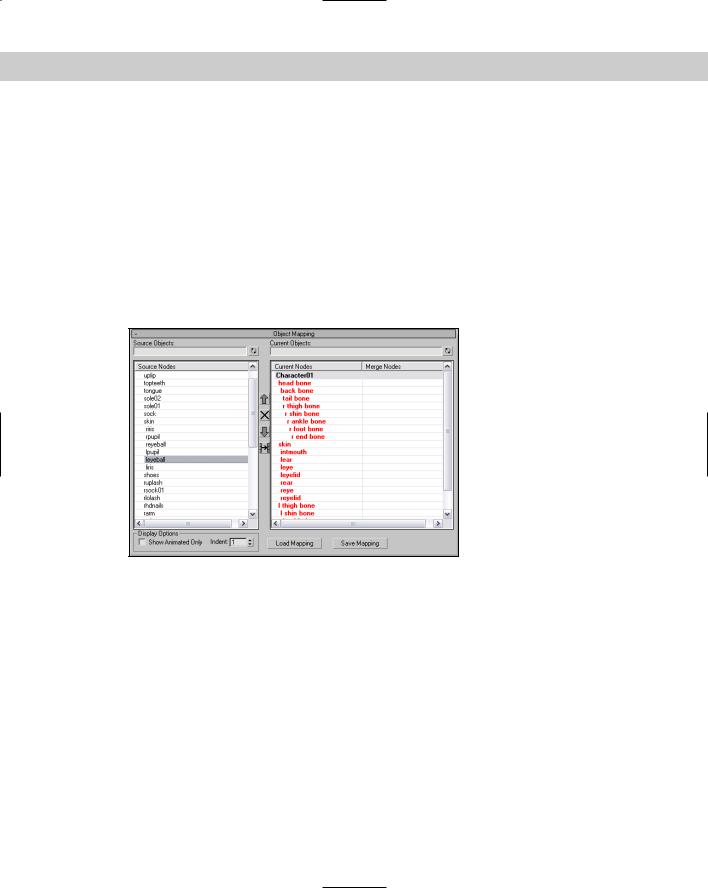
If you use an animation sequence on a bone structure that is different than the source, then you can use the Object Mapping rollout, shown in Figure 36-6. This rollout lists the Source Object and the Current Objects side by side. All the bones that are animated are shown in red. You can save these mappings and load them to other objects. Mappings are saved with the .MAM extension.
Figure 36-6: The Object Mapping rollout defines how one object maps to another.
Using Character Animation Techniques
When it comes to character animation, several techniques can really help. Keeping these points in mind as you animate characters can make a difference:
Use Dynamics: Dynamic packages like reactor can provide incredibly realistic motion based on physical properties. Learning to use this powerful tool for even the most basic animation sequences is worth the effort.
Learn by Example: If you’re working on a cartoon character, then by all means, watch cartoons. Traditional cartoons understand and invented the language of cartoon motion including squash and stretch, exaggerated motion, or scaling eyes large to indicate surprise. If your character motion is more realistic, find the motion, videotape it, and watch it over and over to catch the subtle secondary motion.

894 Part VIII Character Animation
Use Background Animations: The Viewport Background can load animation clips, which can make positioning characters to match real motion easy. This is a poor man’s motion capture system.
Include Secondary Motion: The primary motion of a character is often the main focus, but you can enhance the animation by looking for secondary motion. For example, when a person walks, you see his legs take the steps and his arms moving opposite the legs’ motion, but secondary motion includes his hair swishing back and forth and shoelaces flopping about.
Use the Flex Modifier: The Flex modifier gives soft-bodies, such as tails, hair, ears, and clothing, the realistic secondary motion needed to make them believable.
Use the Morph Modifier: The Morph modifier can be used to morph a character between two poses or to morph its face between the different phonemes as the character talks.
Use IK: The next chapter covers this in detail, but here’s a quick tip: Having a character move by positioning its foot or hand is often much easier than pushing it into position.
Use the Spring Controller: Another good way to get secondary motion is to use the Spring Controller. This controller works well with limbs.
Add Randomness with the Noise Controller: Often, perfect animation sequences don’t look realistic, and using the Noise Controller can help to make a sequence look more realistic, whether the Noise Controller is applied to a walking sequence or to the subtle movement of the eyes.
Use Manipulators: Manipulators can be created and wired to give you control over the animation values of a single motion, such as opening and closing the character’s eyes.
Summary
Characters are becoming more and more important in the Max world and can be saved as separate files just like Max scene files. This chapter covered the following topics:
Creating and saving characters
Managing the various parts of a character
Controlling various skin poses
Merging animation sequences between different characters
Inverse kinematics is a powerful animation feature that is worth the time to use. In the next chapter, you get a chance to work with this feature.
|
|
|
Using Inverse
Kinematics
Kinematics is a branch of mechanics that deals with the motions of a system of objects, so inverse kinematics would be its evil
twin brother that deals with the non-motion of a system of objects. Well, not exactly.
In Max, a system of objects is a bunch of objects that are linked together. After a system is built and the parameters of the links are defined, the motions of all the pieces below the parent object can be determined as the parent moves using kinematic formulas.
Inverse kinematics (IK) is similar, except that it determines all the motions of objects in a system when the last object in the hierarchy chain is moved. The position of the last object, such as a finger or a foot, is typically the one you’re concerned with. Using IK, you can then use these solutions to animate the system of objects by moving the last object in the system.
Forward versus Inverse Kinematics
Before you can understand inverse kinematics (IK), you need to realize that another type of kinematics exists — forward kinematics. Kinematic solutions only work on a kinematic chain, which you can create by linking children objects to their parents.
Cross- |
Chapter 8, “Grouping and Linking Objects,” covers linking objects |
Reference |
and creating kinematic chains. |
|
Forward kinematics causes objects at the bottom of a linked structure to move along with their parents. For example, consider the linked structure of an arm, where the upper arm is connected to a forearm, which is connected to a hand, and finally to some fingers. Using forward kinematics, the lower arm, hand, and fingers all move when the upper arm is moved.
37C H A P T E R
In This Chapter
Understanding forward and inverse kinematics
Using interactive and applied IK methods
Setting thresholds
in the IK panel of the Preference Settings dialog box
Learning to work with the HI, HD, and IK Limb solvers
896 Part VIII Character Animation
Having the linked children move with their parent is what you would expect and want, but suppose the actual object that you wanted to place is the hand. Inverse kinematics (IK) enables child objects to control their parent objects. So, using inverse kinematics, you can drag the hand to the exact position you want, and all other parts in the system follow.
Forward kinematics in Max involves simply transforming linked hierarchies. Anytime you move, rotate, or scale a linked hierarchy, the children move with the parent, but the child object can also be transformed independent of its parent.
Creating an Inverse Kinematics System
Before you can animate an inverse kinematics system, you need to build and link the system, define joints by positioning pivot points, and define any joint constraints you want.
Building and linking a system
The first step in creating an inverse kinematics system is to create and link several objects together. You can create links using the Link button on the main toolbar.
With the linked system created, position the child object’s pivot point at the center of the joint between it and its parent. For example, the joint between an upper and lower arm would be at the elbow, so this is where the pivot point for the lower arm should be located.
Cross- |
Chapter 8, “Grouping and Linking Objects,” covers creating linked systems, and Chapter 10, |
Reference |
“Transforming Objects — Translate, Rotate, and Scale,” covers moving pivot points. |
|
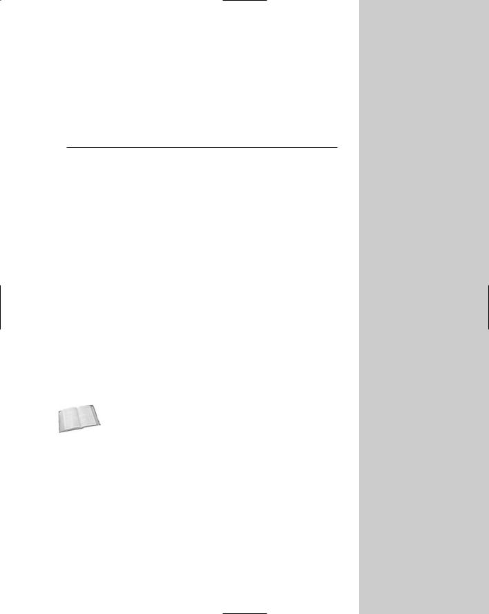
After you create the linked system and correctly position your pivot points, open the Hierarchy panel and click the IK button. Several rollouts open that let you control the IK system, including the Object Parameters rollout shown in Figure 37-1.
Figure 37-1: The IK rollouts let you control the binding of an IK system.

Chapter 37 Using Inverse Kinematics 897
Selecting a terminator
Because child objects in an inverse kinematics system can cause their parents to move, moving a child could cause unwanted movements all the way up the system to the root object. For example, pulling on the little finger of a human model could actually move the head. To prevent this, you can select an object in the system to be a terminator.
A terminator is the last object in the IK system that is affected by the child’s movement. Making the upper arm a terminator would prevent the finger’s movement from affecting any objects above the arm.
To set a terminator, select an object and then enable the Terminator option in the Object Parameters rollout.
For Interactive IK mode, you can also enable the Auto Termination option included in the Auto Termination rollout. The Number (#) of Links Up value sets the terminator a specified number of links above the current selection.
Defining joint constraints
The next step is to define the joint constraints, which you specify in the Sliding Joints and Rotational Joints rollouts. By default, each joint has six degrees of freedom, meaning that the two objects that make up the joint can each move or rotate along the X, Y, or Z axes. The axis settings for all other sliding and rotational joints are identical. Defining joint constraints enables you to constrain these motions in order to prevent unnatural motions, such as an elbow bending backward. To constrain an axis, select the object that includes the pivot point for the joint and, in the appropriate rollout, locate the section for the axis that you want to restrict and deselect the Active option. If an axis’s Active option is deselected, the axis is constrained. You can also limit the motion of joints by selecting the Limited option.
When the Limited option is selected, the object can move only within the bounds set by the From and To values. The Ease option causes the motion of the object to slow as it approaches either limit. The Spring Back option lets you set a rest position for the object; the object returns to this position when pulled away. The Spring Tension sets the amount of force that the object uses to resist being moved from its rest position. The Damping value sets the friction in the joint, which is the value with which the object resists any motion.
Note |
As you enter values in the From and To fields, the object moves to that value to show visually |
|
the location specified. You can also hold down the mouse on the From and To values to cause |
|
the object to move temporally to its limits. These settings are based on the current Reference |
|
Coordinate system. |
Copying, pasting, and mirroring joints
Defining joint constraints can be work — work that you wouldn’t want to have to duplicate if you didn’t have to. The Copy and Paste buttons in the Object Parameters rollout enable you to copy Sliding Joints or Rotational Joints constraints from one IK joint to another.
To use these buttons, select an IK system and click the Copy button; then select each of the joints to be constrained in a similar manner, and click the Paste button. There is also an option to mirror the joints about an axis. It is useful for duplicating an IK system for opposite arms or legs of a human or animal model.

898 Part VIII Character Animation
Binding objects
When using applied IK, you need to bind an object in the IK system to a follow object. The IK joint that is bound to the follow object then follows the follow object around the scene. The bind controls are located in the Hierarchy panel under the Object Parameters rollout. To bind an object to a follow object, click the Bind button in the Object Parameters rollout and select the follow object.
In addition to binding to a follow object, IK joints can also be bound to the world for each axis by position and orientation. This causes the object to be locked in its current position so that it won’t move or rotate along the axis that is selected. You can also assign a Weight value.
When the IK computations determine that two objects need to move in opposite directions, the solution favors the object with the largest Weight value.
The Unbind button eliminates the binding.
Understanding precedence
When Max computes an IK solution, the order in which the joints are solved determines the end result. The Precedence value (located in the Object Parameters rollout) lets you set the order in which joints are solved. To set the precedence for an object, select the object and enter a value in the Precedence value setting. Max computes the object with a higher precedence value first.
The default joint precedence for all objects is 0. This assumes that the objects farthest down the linkage move the most. The Object Parameters rollout also includes two default precedence settings. The Child to Parent button sets the precedence value for the root object to 0 and increments the precedence of each level under the root by 10. The Parent to Child button sets the opposite precedence, with the root object having a value of 0 and the precedence value of each successive object decreasing by 10.
Tutorial: Building an extensible arm linkage
As an example of a kinematics system, we design a simple arm linkage composed of six struts. To the end of this linkage, we attach a rubber spider on a string. (This contraption is perfect for surprising your coworkers in the office.)
To create an inverse kinematics system for an extensible arm, follow these steps:
1.Open the Extensible arm with spider.max file from the Chap 37 directory on the CD-ROM.
This file includes a spider model on the end of a string with several strut objects. The pivot points for the positioned objects have already been moved.
2.Click the Select and Link button on the main toolbar, and link the spider to the string object by selecting the spider and dragging from the spider to the cylinder. The spider then becomes the child to the string object. Next link the string to the last strut and so on back to the first strut.
Chapter 37 Using Inverse Kinematics 899
3.Next we need to define the joint constraints for the system. Open the Hierarchy panel, and click the IK button. In the Object Parameters rollout, select the first strut and enable the Terminator, Bind Position, and Bind Orientation options; doing so prevents the first strut from moving anywhere. In the Sliding and Rotational Joint rollouts, deactivate
all the axes except for the Rotational Z Axis. When this is done, the Active box for the Rotational Z Axis is the only one selected. Then click the Copy buttons for both joint types in the Object Parameters rollout, select each of the other struts in turn, and click both Paste buttons. This copies the joint constraints from the first strut to the other strut objects. For the string object, make all Rotational Joint axes active.
4.To test the system, select the Interactive IK button in the Inverse Kinematics rollout and select and move the spider.
All the struts rotate together as the spider moves.
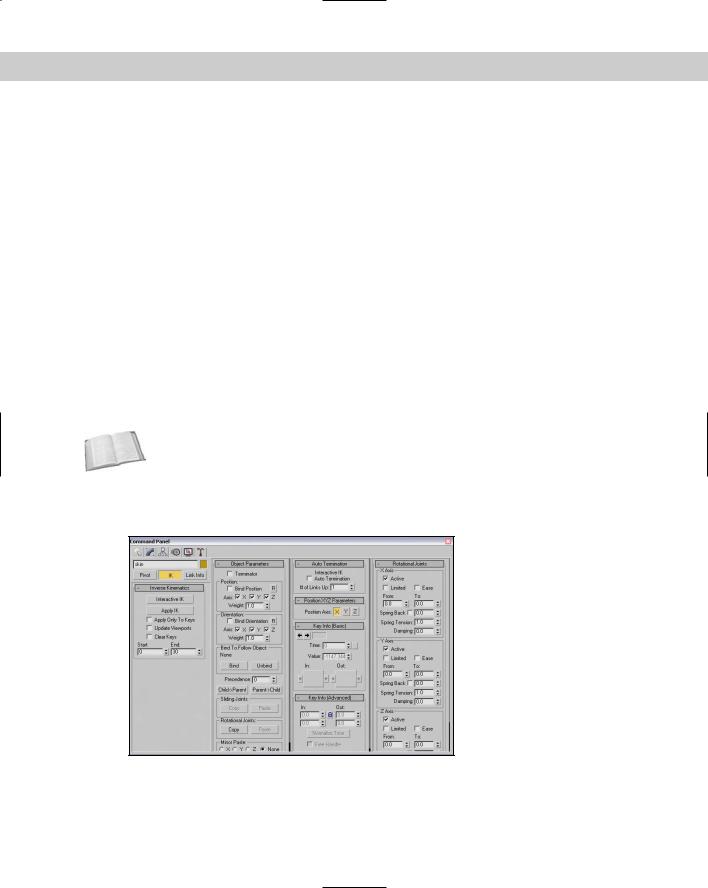
Figure 37-2 shows the struts bending to follow the spider as it is moved downward. Notice for this system that the first strut doesn’t move or rotate and that all the struts can be rotated only along the Z axis, but that the spider can move freely within the range of the string. With the Interactive IK mode disabled, any object can be moved and/or rotated and only the links are enforced.
Figure 37-2: The objects in this scene are part of an inverse kinematics system.