

266 Part II Working with Objects
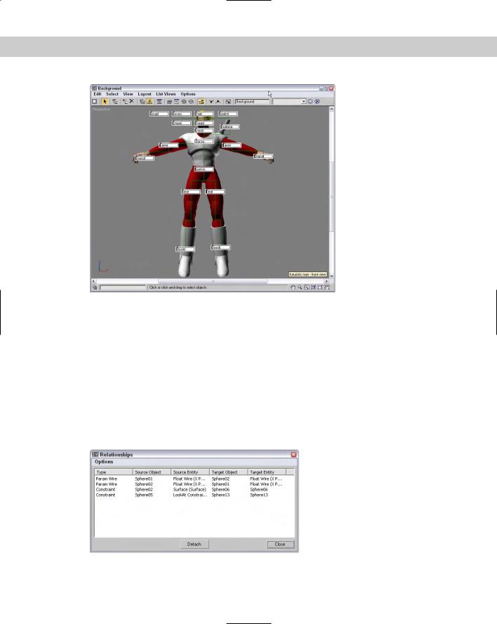
Figure 9-12: Using a background image, you can see how the links relate to the model.
Using List Views
One of the last uses of the Schematic View is to list all nodes that have things in common. Using the List Views menu, you can select to see All Relationships, Selected Relationships, All Instances, Selected Instances, Show Occurrences, and All Animated Controllers.
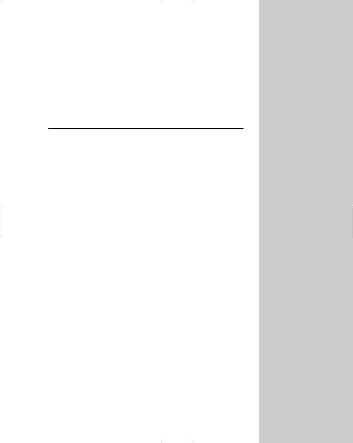
The List Views All Relationships menu command displays a separate dialog box, shown in Figure 9-13, containing a list of nodes and their relationships. The Selected Relationships menu command limits the list to only selected objects with relationships. The List Views dialog box also includes a Detach button to remove the relationships if desired. Double-clicking on a relationship in the list opens its dialog box, where you can edit the relationship.
Figure 9-13: The List Views dialog box includes a list of nodes with relationships.

Chapter 9 Working with the Schematic View 267
The List Views All Instances menu command displays all the instances found in the scene. This includes all types of instances, including geometry, modifiers, controllers, and so on. For the Instances list view, the Detach button is replaced with a Make Unique button.
Note Another way to identify instances is to look for bold text in the node. All label text for all instanced nodes is displayed in bold.
If a node is selected and you want to see all other nodes that share the same type of relationship or that share a property, the List Views Show Occurrences displays them. The final list view shows All Animated Controllers.
Summary
Some tasks in the viewport, such as linking objects into a hierarchy, can be difficult. The Schematic View represents all data as simple rectangular nodes. These nodes make easy work of accomplishing a variety of tasks.
In this chapter, you’ve done the following:
Viewed all objects as nodes using the Schematic View window
Learned the Schematic View interface
Used the Schematic View window to select, delete, and copy objects, materials, and modifiers
Used the Schematic View to assign controllers and wire parameters
Set preferences for the Schematic View window
Listed views of nodes with common properties.
In the next chapter, you learn how to transform objects using the move, rotate, and scale features — finally, some motion for our static scenes.
|
|
|

Transforming
Objects — Translate,
Rotate, and Scale
Although a transformation sounds like something that would happen during the climax of a superhero film, transformation is sim-
ply the process of “repositioning” or changing an object’s position, rotation, or scale. So moving an object from here to there is a transformation. Superman would be so jealous.
Transformations occur when you select an object or objects, click one of the transformation buttons located on the main toolbar, and then then drag one of the transformation gizmo handles in the viewport to transform the object. Max includes various tools to help in the transformation of objects, including the Transform Gizmos, the Transform Type-In dialog box, and the Transform Managers.
This chapter covers each of these tools and several others that make transformations more automatic, such as the alignment, grid, and snap features.
Translating, Rotating, and Scaling
Objects
So you have an object created and it’s just sitting there — sitting and waiting. Waiting for what? Waiting to be transformed. To be moved a little to the left or to be rotated around to show its good side or to be scaled down a little smaller. These actions are called transformations because they transform the object to a different state.
Transformations are different from modifications. Modifications change the object’s geometry, but transformations do not affect the object’s geometry at all.
The three different types of transformations are translation (which is a fancy word for moving objects), rotation, and scaling.
10C H A P T E R
In This Chapter
Transforming objects
Controlling transformations with the Transform Gizmos, the Transform Type-Ins, and the Transform Managers
Working with pivot points and axis constraints
Aligning objects with the align tools
Using grids and snapping objects to common points
270 Part II Working with Objects
Translating objects
The first transformation type is translation or moving objects. You can move objects along any of the three axes or within the three planes. You can move objects to an absolute coordinate location or move them to a certain offset distance from their current location.
To move objects, click the Select and Move button on the main toolbar (or press the W key), select the object to move, and drag the object in the viewport to the desired
location. Translations are measured in the defined system units for the scene, which may be inches, centimeters, meters, and so on.
Rotating objects
Rotation is the process of spinning the object about its Transform Center point. To rotate objects, click the Select and Rotate button on the main toolbar (or press the E
key), select an object to rotate, and drag it in a viewport. Rotations are measured in degrees, where 360 degrees is a full rotation.
Scaling objects
Scaling increases or decreases the overall size of an object. Most scaling operations are uniform, or equal in all directions. All Scaling is done about the Transform Center point.
To scale objects uniformly, click the Select and Uniform Scale button on the main toolbar (or press the R key), select an object to scale, and drag it in a viewport. Scalings are
measured as a percentage of the original. For example, a cube that is scaled to a value of 200 percent is twice as big as the original.
Non-uniform scaling
The Select and Scale button includes two flyout buttons for scaling objects non-uniformly, allowing objects to be scaled unequally in different dimensions. The two additional
tools are Select and Non-Uniform Scale, and Select and Squash, shown in Table 10-1. Resizing a basketball with the Select and Non-Uniform Scale tool could result in a ball that is oblong and taller than it is wide. Scaling is done about the axis or axes that have been constrained (or limited) using the Restrict Axes buttons on the Axis Constraints toolbar.
Squashing objects
The Squash option is a specialized type of non-uniform scaling. This scaling causes the constrained axis to be scaled at the same time that the opposite axes are scaled in the
opposite direction. For example, if you push down on the basketball by scaling the Z-axis, the sides, or the X- and Y-axes, it bulges outward. This simulates the actual results of such materials as rubber and plastic.
Tip |
You can cycle through the different Scaling tools by repeatedly pressing the R key. |
Figure 10-1 shows a basketball that has been scaled using uniform scaling, non-uniform scaling, and squash modes.