

- •Preface
- •About This Book
- •Acknowledgments
- •Contents at a Glance
- •Contents
- •Relaxing at the Beach
- •Dressing the Scene
- •Animating Motion
- •Rendering the Final Animation
- •Summary
- •The Interface Elements
- •Using the Menus
- •Using the Toolbars
- •Using the Viewports
- •Using the Command Panel
- •Using the Lower Interface Bar Controls
- •Interacting with the Interface
- •Getting Help
- •Summary
- •Understanding 3D Space
- •Using the Viewport Navigation Controls
- •Configuring the Viewports
- •Working with Viewport Backgrounds
- •Summary
- •Working with Max Scene Files
- •Setting File Preferences
- •Importing and Exporting
- •Referencing External Objects
- •Using the File Utilities
- •Accessing File Information
- •Summary
- •Customizing Modify and Utility Panel Buttons
- •Working with Custom Interfaces
- •Configuring Paths
- •Selecting System Units
- •Setting Preferences
- •Summary
- •Creating Primitive Objects
- •Exploring the Primitive Object Types
- •Summary
- •Selecting Objects
- •Setting Object Properties
- •Hiding and Freezing Objects
- •Using Layers
- •Summary
- •Cloning Objects
- •Understanding Cloning Options
- •Mirroring Objects
- •Cloning over Time
- •Spacing Cloned Objects
- •Creating Arrays of Objects
- •Summary
- •Working with Groups
- •Building Assemblies
- •Building Links between Objects
- •Displaying Links and Hierarchies
- •Working with Linked Objects
- •Summary
- •Using the Schematic View Window
- •Working with Hierarchies
- •Setting Schematic View Preferences
- •Using List Views
- •Summary
- •Working with the Transformation Tools
- •Using Pivot Points
- •Using the Align Commands
- •Using Grids
- •Using Snap Options
- •Summary
- •Exploring the Modifier Stack
- •Exploring Modifier Types
- •Summary
- •Exploring the Modeling Types
- •Working with Subobjects
- •Modeling Helpers
- •Summary
- •Drawing in 2D
- •Editing Splines
- •Using Spline Modifiers
- •Summary
- •Creating Editable Mesh and Poly Objects
- •Editing Mesh Objects
- •Editing Poly Objects
- •Using Mesh Editing Modifiers
- •Summary
- •Introducing Patch Grids
- •Editing Patches
- •Using Modifiers on Patch Objects
- •Summary
- •Creating NURBS Curves and Surfaces
- •Editing NURBS
- •Working with NURBS
- •Summary
- •Morphing Objects
- •Creating Conform Objects
- •Creating a ShapeMerge Object
- •Creating a Terrain Object
- •Using the Mesher Object
- •Working with BlobMesh Objects
- •Creating a Scatter Object
- •Creating Connect Objects
- •Modeling with Boolean Objects
- •Creating a Loft Object
- •Summary
- •Understanding the Various Particle Systems
- •Creating a Particle System
- •Using the Spray and Snow Particle Systems
- •Using the Super Spray Particle System
- •Using the Blizzard Particle System
- •Using the PArray Particle System
- •Using the PCloud Particle System
- •Using Particle System Maps
- •Controlling Particles with Particle Flow
- •Summary
- •Understanding Material Properties
- •Working with the Material Editor
- •Using the Material/Map Browser
- •Using the Material/Map Navigator
- •Summary
- •Using the Standard Material
- •Using Shading Types
- •Accessing Other Parameters
- •Using External Tools
- •Summary
- •Using Compound Materials
- •Using Raytrace Materials
- •Using the Matte/Shadow Material
- •Using the DirectX 9 Shader
- •Applying Multiple Materials
- •Material Modifiers
- •Summary
- •Understanding Maps
- •Understanding Material Map Types
- •Using the Maps Rollout
- •Using the Map Path Utility
- •Using Map Instances
- •Summary
- •Mapping Modifiers
- •Using the Unwrap UVW modifier
- •Summary
- •Working with Cameras
- •Setting Camera Parameters
- •Summary
- •Using the Camera Tracker Utility
- •Summary
- •Using Multi-Pass Cameras
- •Creating Multi-Pass Camera Effects
- •Summary
- •Understanding the Basics of Lighting
- •Getting to Know the Light Types
- •Creating and Positioning Light Objects
- •Viewing a Scene from a Light
- •Altering Light Parameters
- •Working with Photometric Lights
- •Using the Sunlight and Daylight Systems
- •Using Volume Lights
- •Summary
- •Selecting Advanced Lighting
- •Using Local Advanced Lighting Settings
- •Tutorial: Excluding objects from light tracing
- •Summary
- •Understanding Radiosity
- •Using Local and Global Advanced Lighting Settings
- •Working with Advanced Lighting Materials
- •Using Lighting Analysis
- •Summary
- •Using the Time Controls
- •Working with Keys
- •Using the Track Bar
- •Viewing and Editing Key Values
- •Using the Motion Panel
- •Using Ghosting
- •Animating Objects
- •Working with Previews
- •Wiring Parameters
- •Animation Modifiers
- •Summary
- •Understanding Controller Types
- •Assigning Controllers
- •Setting Default Controllers
- •Examining the Various Controllers
- •Summary
- •Working with Expressions in Spinners
- •Understanding the Expression Controller Interface
- •Understanding Expression Elements
- •Using Expression Controllers
- •Summary
- •Learning the Track View Interface
- •Working with Keys
- •Editing Time
- •Editing Curves
- •Filtering Tracks
- •Working with Controllers
- •Synchronizing to a Sound Track
- •Summary
- •Understanding Your Character
- •Building Bodies
- •Summary
- •Building a Bones System
- •Using the Bone Tools
- •Using the Skin Modifier
- •Summary
- •Creating Characters
- •Working with Characters
- •Using Character Animation Techniques
- •Summary
- •Forward versus Inverse Kinematics
- •Creating an Inverse Kinematics System
- •Using the Various Inverse Kinematics Methods
- •Summary
- •Creating and Binding Space Warps
- •Understanding Space Warp Types
- •Combining Particle Systems with Space Warps
- •Summary
- •Understanding Dynamics
- •Using Dynamic Objects
- •Defining Dynamic Material Properties
- •Using Dynamic Space Warps
- •Using the Dynamics Utility
- •Using the Flex Modifier
- •Summary
- •Using reactor
- •Using reactor Collections
- •Creating reactor Objects
- •Calculating and Previewing a Simulation
- •Constraining Objects
- •reactor Troubleshooting
- •Summary
- •Understanding the Max Renderers
- •Previewing with ActiveShade
- •Render Parameters
- •Rendering Preferences
- •Creating VUE Files
- •Using the Rendered Frame Window
- •Using the RAM Player
- •Reviewing the Render Types
- •Using Command-Line Rendering
- •Creating Panoramic Images
- •Getting Printer Help
- •Creating an Environment
- •Summary
- •Creating Atmospheric Effects
- •Using the Fire Effect
- •Using the Fog Effect
- •Summary
- •Using Render Elements
- •Adding Render Effects
- •Creating Lens Effects
- •Using Other Render Effects
- •Summary
- •Using Raytrace Materials
- •Using a Raytrace Map
- •Enabling mental ray
- •Summary
- •Understanding Network Rendering
- •Network Requirements
- •Setting up a Network Rendering System
- •Starting the Network Rendering System
- •Configuring the Network Manager and Servers
- •Logging Errors
- •Using the Monitor
- •Setting up Batch Rendering
- •Summary
- •Compositing with Photoshop
- •Video Editing with Premiere
- •Video Compositing with After Effects
- •Introducing Combustion
- •Using Other Compositing Solutions
- •Summary
- •Completing Post-Production with the Video Post Interface
- •Working with Sequences
- •Adding and Editing Events
- •Working with Ranges
- •Working with Lens Effects Filters
- •Summary
- •What Is MAXScript?
- •MAXScript Tools
- •Setting MAXScript Preferences
- •Types of Scripts
- •Writing Your Own MAXScripts
- •Learning the Visual MAXScript Editor Interface
- •Laying Out a Rollout
- •Summary
- •Working with Plug-Ins
- •Locating Plug-Ins
- •Summary
- •Low-Res Modeling
- •Using Channels
- •Using Vertex Colors
- •Rendering to a Texture
- •Summary
- •Max and Architecture
- •Using AEC Objects
- •Using Architectural materials
- •Summary
- •Tutorial: Creating Icy Geometry with BlobMesh
- •Tutorial: Using Caustic Photons to Create a Disco Ball
- •Summary
- •mental ray Rendering System
- •Particle Flow
- •reactor 2.0
- •Schematic View
- •BlobMesh
- •Spline and Patch Features
- •Import and Export
- •Shell Modifier
- •Vertex Paint and Channel Info
- •Architectural Primitives and Materials
- •Minor Improvements
- •Choosing an Operating System
- •Hardware Requirements
- •Installing 3ds max 6
- •Authorizing the Software
- •Setting the Display Driver
- •Updating Max
- •Moving Max to Another Computer
- •Using Keyboard Shortcuts
- •Using the Hotkey Map
- •Main Interface Shortcuts
- •Dialog Box Shortcuts
- •Miscellaneous Shortcuts
- •System Requirements
- •Using the CDs with Windows
- •What’s on the CDs
- •Troubleshooting
- •Index
668 Part V Cameras
|
Point from the list, and clicking the new location, or by changing the X and Y values. |
|
Click the Modify Camera button after moving the Camera Point’s position to realign the |
|
camera. |
Caution |
If you get an error, the camera is not created. The most likely error is that you have assigned |
|
a position to the wrong Camera Point. Check the positions of each Camera Point, and try |
|
again. |
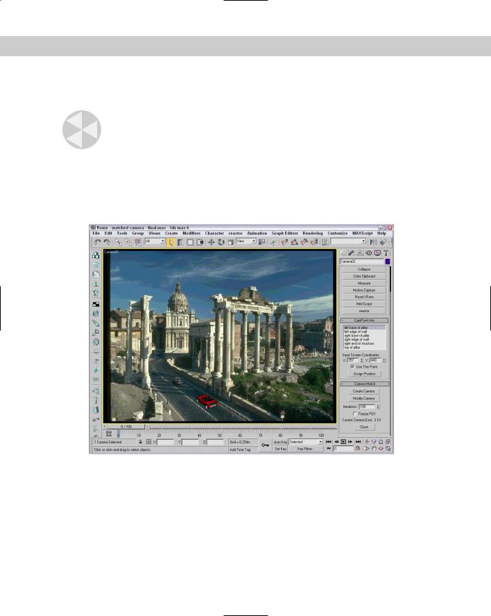
5.With the camera positioned to match the background, you can position the car so that it is correctly aligned with the other cars in the image. Select the Porsche model, scale it down, and position it in the Camera viewport on the road. Turn off the construction grid by pressing the G key on the keyboard.
Figure 25-2 shows our current scene from the matched camera perspective.
Figure 25-2: The matched camera view with a car inserted into the scene
Using the Camera Tracker Utility
The Camera Tracker utility recreates the movements of a camera that was used to create an animated background. As with the Camera Match utility, you access the Camera Tracker utility from the Utilities panel. Click the More button to open the Utilities dialog box, and select the Camera Tracker from the list of additional utilities.
Chapter 25 Matching and Tracking Cameras 669
Loading a movie file
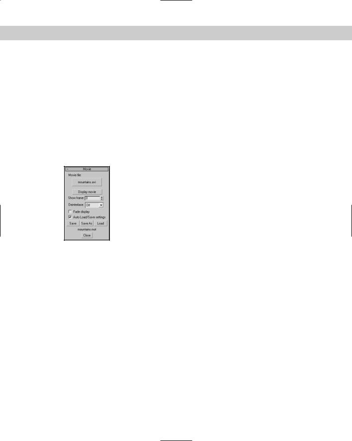
One of the first tasks is to load a movie file to track. You can do so using the Movie File button (initially labeled “none”) found in the Movie rollout, shown in Figure 25-3. This button opens the Browse Image for Input dialog box, where you can select a movie file to load. Usable formats include .AVI, .MOV, .FLC, and .IFL. After you select a movie file, the button’s label changes to the name of the movie file. The Movie rollout also includes a Display Movie button to view a single frame of the movie. The Show Frame value lets you display a specific frame of the movie.
You can set the Deinterlace option to Off, Odd, or Even and, if enabled, it de-interlaces a video file using odd or even lines. This feature enables you to view interlaced video segments whose individual frames include only odd or even lines. The Fade Display option fades the movie by 50 percent so you can clearly see the tracker gizmos. (See the next section for more about tracker gizmos.)
Figure 25-3: The Movie rollout lets you load and view a movie file.
The Movie rollout also includes buttons to Save, Save As, and Load camera tracker setting files, which are saved with the .MOT extension. The Auto Load/Save Setting option automatically saves these files in the same directory as the movie file; they are automatically updated when any of the settings change.
Working with trackers
The Camera Tracker utility uses Camera Points, just as the Camera Match utility does. Camera Points can be set up in the same manner discussed in the previous section. The Camera Tracker utility requires a minimum of six Camera Points and at least two that are in separate planes.
These Camera Points become the motion trackers for the utility. Motion trackers are points that are followed throughout the animation. These points are used to compute the camera’s path. You display and control these trackers using the Motion Trackers rollout, shown in Figure 25-4. To add a tracker to the list, click the New Tracker button. This places the tracker gizmo in the list. You can change the parameters for the gizmo and move the gizmo as needed.
The Scene Object button lets you select a Camera Point or some other object as the object to track. You can also specify values for Match Weights and Max Move per Frame. The higher the Match Weights value, the more consistent the track points in the scene are.
670 Part V Cameras
The Set Start and Set Stop buttons let you set the frames at which the tracking starts and stops. If a tracking object moves out of the scene, click the Set Stop button at the frame where it disappears.
Figure 25-4: The Motion Trackers rollout lets you add trackers to the scene.
Using the tracker gizmo
The tracker gizmo looks like a box within a box. The crosshairs mark the center of the tracking object, the inner box (called the Feature Selection box) marks the edges of the tracking object, and the outer box (called the Motion Search box) determines the search area in which the tracker gizmo looks for the object in each frame. Figure 25-5 shows the tracker gizmo.
Feature Selection box
Motion Search box
Center of gizmo
Figure 25-5: You use the tracker gizmo to track objects through several frames.
Chapter 25 Matching and Tracking Cameras 671
Stepping through frames
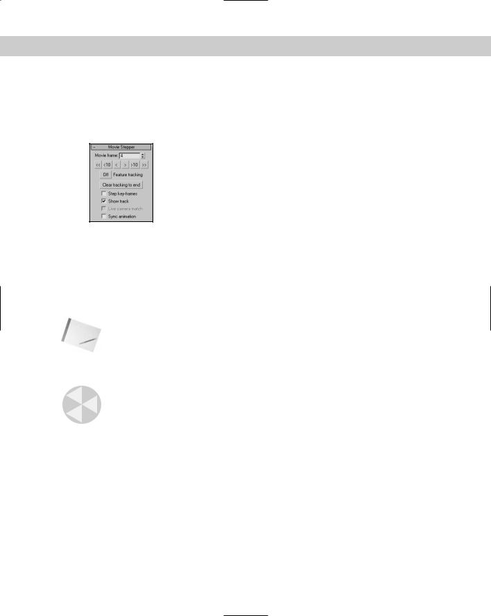
You use the Movie Stepper rollout, shown in Figure 25-6, to step through the animation frames. This feature is useful for ensuring that the tracking objects are visible throughout the entire animation. You can also use this rollout to manually set the tracking.
Figure 25-6: The Movie Stepper rollout lets you step through the movie frames.
The Movie Frame spinner displays the current frame. The buttons under the frame number let you move forward or backward through the frames. These buttons can move to the beginning frame, back ten frames, back one frame, forward one frame, forward ten frames, or to the last frame.
The Feature tracking button, when enabled, computes the tracking locations; the tracker gizmos move to their tracked positions if the positions have already been tracked. The Step Keyframes option lets you move between keyframes instead of frames using the stepping buttons. The Show Track option displays the path traveled by each tracker as a line.
Note Red track lines indicate that the tracker has been tracked. White track lines are trackers that haven’t been tracked.
The Live Camera Match option moves the camera as you reposition the tracker gizmos. The Sync Animation option causes the Time slider and the viewports to update along with the Movie Stepper buttons.
Caution |
Be aware that updating the viewports with the Sync Animation option can slow down the |
|
system substantially. |
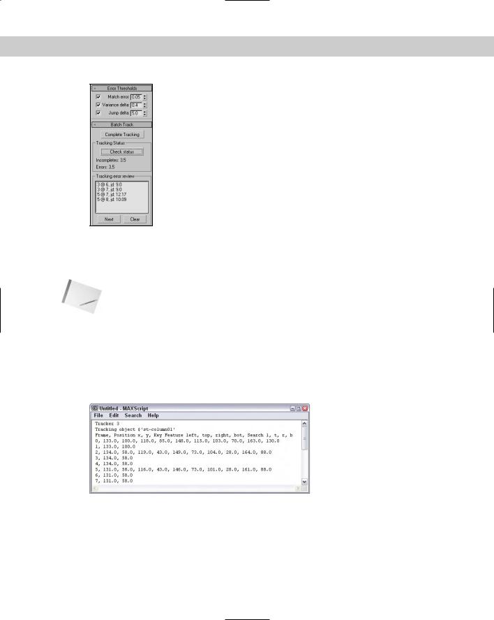
The Error Threshold rollout, shown in Figure 25-7, lets you set the maximum allowable error values for Match Error, Variance Delta, and Jump Delta. Match Error measures the differences in the current frame to the best match. The Variance Delta is a measure of the difference in color between the target and the match, and the Jump Delta looks at the distance the tracker has moved in the current frame compared to the last five frames. If the tracking exceeds these values, an error appears in the Tracking Error Review list in the Batch Track rollout.
Automating the tracking process
After the parameters have been set up, you can use the Complete Tracking button in the Batch Track rollout, also shown in Figure 25-7, to start the tracking process. As tracking proceeds, any errors are captured and displayed in the Tracking Error Review list. After reviewing the errors, go to the Movie Stepper rollout to correct them, and run the tracking process again. This iterative process produces the best results.
672 Part V Cameras
Figure 25-7: The Error Threshold rollout lets you specify which errors to flag, and the Batch Track rollout lets you initialize tracking.
The Complete Tracking button initiates the tracking process. This process tracks only those frames that haven’t been tracked yet. The Check Status button checks for errors and for any frames that haven’t been tracked. Any errors are displayed in the Tracking Error Review list, and the tracks that haven’t been completed are displayed next to the Incomplete label.
Note Each error listed displays the tracker number, the frame number, an error code, and the threshold value. Possible error codes include “me” for match error, “vd” for color variance error, and “jd” for jump error.
The Next button moves to the next error in the list, and the Clear button removes an error from the list.
The Position Data rollout lets you clear, show, or export the tracking data for the selected tracker, the enabled trackers, or all trackers. The Show Data button opens the data in a text window, shown in Figure 25-8. You can save exported data as an Excel spreadsheet in the .CSV format or as text with the .DAT extension.
Figure 25-8: The Show Data button in the Position Data rollout displays the tracking data in a text window.
Chapter 25 Matching and Tracking Cameras 673
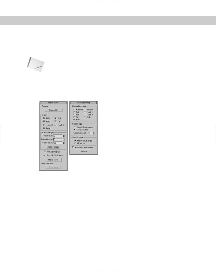
Matching the camera
After all the tracking positions have been established, you need to select a camera to match the tracking data. In the Match Move rollout, shown in Figure 25-9, is a Camera button (initially labeled “none”). Click this button to select the camera to use.
Note |
The camera specified in the Match Move rollout must be a Free camera. |
While matching the camera, you can specify which camera parameters to include in the process. Options include FOV, Pan, Truck H (horizontal), Dolly, Roll, Tilt, and Truck V (vertical). You can also specify the Movie Start and Animation Start frames, as well as the Frame Count. The Reset Ranges button resets the Movie Start, Animation Start, and Frame Count values to their defaults.
Figure 25-9: The Match Move and Move Smoothing rollouts let you select a camera to match to the tracking data and smooth the camera’s motion.
The Animate Displays option updates the viewport frame by frame with the camera match. The Generate Keyframes option creates keys for each frame of the match. When you’re all ready, the Match Move button starts the Match Move process. The Maximum Pixel Error displays the tracking error for each frame. To view all the error values in a text window, click the Show Errors button.
Smoothing the camera motion
After the camera is matched to the tracking data, its motion might be a little erratic and bumpy. You can smooth its motion using the Move Smoothing rollout, also shown in Figure 25-9. This rollout lets you select which options to include in the smoothing calculations: Rotation, Roll, Pan, Tilt, FOV, Position, Truck H (horizontal), Truck V (vertical), or Dolly.

674 Part V Cameras
The two smooth types that you can choose from are Straight Line Average and Low Pass Filter with a Smooth Amount. You can also smooth just the Match Move Range or All Frames. With the options set, click the Smooth button to initiate the smoothing calculations.
Pinning objects
After the tracked data is captured, you can select an object to follow the path that is positioned in front of the camera. This technique is called pinning. In the Object Pinning rollout, shown in Figure 25-10, select a tracker from the drop-down list and click the Object to Pin button. Then select the object to pin in the viewport. You can also set a Pin Range, the Pin Space (Screen or Grid), and Pin Mode (Absolute or Relative). To complete the pinning, click the Pin button.
Figure 25-10: Use the Object Pinning rollout to position an object in front of the camera path.
Tutorial: Tracking a camera zooming past traffic cones
For this example, I’ve animated a camera that zooms over and past a series of orange traffic cones. The scene includes some trees that will be useful in establishing tracking points.
To track a camera that is zooming past some traffic cones, follow these steps.
1.Open the Tracking past cones.max file from the Chap 25 directory on the CD-ROM. This file includes the same objects used to create the animation, but the camera and its path have been deleted.
2.Open the Utilities panel and click the More button. Then select the Camera Tracker utility and click OK.
3.In the Movie rollout, click the Movie file button and select the Camera past cones.avi file from the Chap 25 directory on the CD-ROM. The movie file appears.
4.Move the movie display out of the way and select Create Helpers Camera Point. Name the camera point object cone 01 and position it at the top-left corner of the cone in the Front viewport. Create, name, and position similar camera points for all six cones and the three trees.
5.Select the Utilities panel and, in the Motion Trackers rollout, click the New Tracker button. A Tracker gizmo appears in the movie display labeled 1. Click the Scene Object button, press the H key to open the Select Objects dialog box, and select the matching camera point for cone 01. Drag the gizmo and center it on the top-left corner of the first

Chapter 25 Matching and Tracking Cameras 675
cone. Move through the movie’s frames in the Movie Stepper rollout and for each frame drag the tracker gizmo to the cone’s new location. When the cone leaves the scene at frame 3, click the Set Stop button in the Motion Trackers rollout.
6.Repeat step 4 to create additional trackers for the remaining cones and the trees. If the point you’re tracking is obscured or goes off the screen, skip that frame.
7.Once the gizmos have been positioned for all relevant frames, click the Complete Tracking button in the Batch Track rollout. When the tracking process completes, press the Check Status button and note the listed Incompletes. Return to the trackers for the frames marked incomplete and add some tracking points. Continue this step until the Check Status button returns a None for the Incompletes.
8.Select Create Cameras Free Camera and click in the Top viewport to create a camera. In the Match Move rollout in the Utilities panel, click the Camera button and select the scene camera in the Top viewport. Then click the Match Move button. If any errors appear, note the frame number and click Ok to continue. After Match Move is complete, you can go back and fix the frames that gave you errors.
9.Select the Perspective viewport and press the C key to change it to the camera view. Then, press the Play button (/) to see the final camera tracking.
Figure 25-11 shows scene after camera tracking has been completed. Notice that the keys are positioned along the Track Bar except for the end of the animation, where tracking produced some errors.
Figure 25-11: Be sure the scene includes several unique trackable objects before trying to track a camera.