

- •Preface
- •About This Book
- •Acknowledgments
- •Contents at a Glance
- •Contents
- •Relaxing at the Beach
- •Dressing the Scene
- •Animating Motion
- •Rendering the Final Animation
- •Summary
- •The Interface Elements
- •Using the Menus
- •Using the Toolbars
- •Using the Viewports
- •Using the Command Panel
- •Using the Lower Interface Bar Controls
- •Interacting with the Interface
- •Getting Help
- •Summary
- •Understanding 3D Space
- •Using the Viewport Navigation Controls
- •Configuring the Viewports
- •Working with Viewport Backgrounds
- •Summary
- •Working with Max Scene Files
- •Setting File Preferences
- •Importing and Exporting
- •Referencing External Objects
- •Using the File Utilities
- •Accessing File Information
- •Summary
- •Customizing Modify and Utility Panel Buttons
- •Working with Custom Interfaces
- •Configuring Paths
- •Selecting System Units
- •Setting Preferences
- •Summary
- •Creating Primitive Objects
- •Exploring the Primitive Object Types
- •Summary
- •Selecting Objects
- •Setting Object Properties
- •Hiding and Freezing Objects
- •Using Layers
- •Summary
- •Cloning Objects
- •Understanding Cloning Options
- •Mirroring Objects
- •Cloning over Time
- •Spacing Cloned Objects
- •Creating Arrays of Objects
- •Summary
- •Working with Groups
- •Building Assemblies
- •Building Links between Objects
- •Displaying Links and Hierarchies
- •Working with Linked Objects
- •Summary
- •Using the Schematic View Window
- •Working with Hierarchies
- •Setting Schematic View Preferences
- •Using List Views
- •Summary
- •Working with the Transformation Tools
- •Using Pivot Points
- •Using the Align Commands
- •Using Grids
- •Using Snap Options
- •Summary
- •Exploring the Modifier Stack
- •Exploring Modifier Types
- •Summary
- •Exploring the Modeling Types
- •Working with Subobjects
- •Modeling Helpers
- •Summary
- •Drawing in 2D
- •Editing Splines
- •Using Spline Modifiers
- •Summary
- •Creating Editable Mesh and Poly Objects
- •Editing Mesh Objects
- •Editing Poly Objects
- •Using Mesh Editing Modifiers
- •Summary
- •Introducing Patch Grids
- •Editing Patches
- •Using Modifiers on Patch Objects
- •Summary
- •Creating NURBS Curves and Surfaces
- •Editing NURBS
- •Working with NURBS
- •Summary
- •Morphing Objects
- •Creating Conform Objects
- •Creating a ShapeMerge Object
- •Creating a Terrain Object
- •Using the Mesher Object
- •Working with BlobMesh Objects
- •Creating a Scatter Object
- •Creating Connect Objects
- •Modeling with Boolean Objects
- •Creating a Loft Object
- •Summary
- •Understanding the Various Particle Systems
- •Creating a Particle System
- •Using the Spray and Snow Particle Systems
- •Using the Super Spray Particle System
- •Using the Blizzard Particle System
- •Using the PArray Particle System
- •Using the PCloud Particle System
- •Using Particle System Maps
- •Controlling Particles with Particle Flow
- •Summary
- •Understanding Material Properties
- •Working with the Material Editor
- •Using the Material/Map Browser
- •Using the Material/Map Navigator
- •Summary
- •Using the Standard Material
- •Using Shading Types
- •Accessing Other Parameters
- •Using External Tools
- •Summary
- •Using Compound Materials
- •Using Raytrace Materials
- •Using the Matte/Shadow Material
- •Using the DirectX 9 Shader
- •Applying Multiple Materials
- •Material Modifiers
- •Summary
- •Understanding Maps
- •Understanding Material Map Types
- •Using the Maps Rollout
- •Using the Map Path Utility
- •Using Map Instances
- •Summary
- •Mapping Modifiers
- •Using the Unwrap UVW modifier
- •Summary
- •Working with Cameras
- •Setting Camera Parameters
- •Summary
- •Using the Camera Tracker Utility
- •Summary
- •Using Multi-Pass Cameras
- •Creating Multi-Pass Camera Effects
- •Summary
- •Understanding the Basics of Lighting
- •Getting to Know the Light Types
- •Creating and Positioning Light Objects
- •Viewing a Scene from a Light
- •Altering Light Parameters
- •Working with Photometric Lights
- •Using the Sunlight and Daylight Systems
- •Using Volume Lights
- •Summary
- •Selecting Advanced Lighting
- •Using Local Advanced Lighting Settings
- •Tutorial: Excluding objects from light tracing
- •Summary
- •Understanding Radiosity
- •Using Local and Global Advanced Lighting Settings
- •Working with Advanced Lighting Materials
- •Using Lighting Analysis
- •Summary
- •Using the Time Controls
- •Working with Keys
- •Using the Track Bar
- •Viewing and Editing Key Values
- •Using the Motion Panel
- •Using Ghosting
- •Animating Objects
- •Working with Previews
- •Wiring Parameters
- •Animation Modifiers
- •Summary
- •Understanding Controller Types
- •Assigning Controllers
- •Setting Default Controllers
- •Examining the Various Controllers
- •Summary
- •Working with Expressions in Spinners
- •Understanding the Expression Controller Interface
- •Understanding Expression Elements
- •Using Expression Controllers
- •Summary
- •Learning the Track View Interface
- •Working with Keys
- •Editing Time
- •Editing Curves
- •Filtering Tracks
- •Working with Controllers
- •Synchronizing to a Sound Track
- •Summary
- •Understanding Your Character
- •Building Bodies
- •Summary
- •Building a Bones System
- •Using the Bone Tools
- •Using the Skin Modifier
- •Summary
- •Creating Characters
- •Working with Characters
- •Using Character Animation Techniques
- •Summary
- •Forward versus Inverse Kinematics
- •Creating an Inverse Kinematics System
- •Using the Various Inverse Kinematics Methods
- •Summary
- •Creating and Binding Space Warps
- •Understanding Space Warp Types
- •Combining Particle Systems with Space Warps
- •Summary
- •Understanding Dynamics
- •Using Dynamic Objects
- •Defining Dynamic Material Properties
- •Using Dynamic Space Warps
- •Using the Dynamics Utility
- •Using the Flex Modifier
- •Summary
- •Using reactor
- •Using reactor Collections
- •Creating reactor Objects
- •Calculating and Previewing a Simulation
- •Constraining Objects
- •reactor Troubleshooting
- •Summary
- •Understanding the Max Renderers
- •Previewing with ActiveShade
- •Render Parameters
- •Rendering Preferences
- •Creating VUE Files
- •Using the Rendered Frame Window
- •Using the RAM Player
- •Reviewing the Render Types
- •Using Command-Line Rendering
- •Creating Panoramic Images
- •Getting Printer Help
- •Creating an Environment
- •Summary
- •Creating Atmospheric Effects
- •Using the Fire Effect
- •Using the Fog Effect
- •Summary
- •Using Render Elements
- •Adding Render Effects
- •Creating Lens Effects
- •Using Other Render Effects
- •Summary
- •Using Raytrace Materials
- •Using a Raytrace Map
- •Enabling mental ray
- •Summary
- •Understanding Network Rendering
- •Network Requirements
- •Setting up a Network Rendering System
- •Starting the Network Rendering System
- •Configuring the Network Manager and Servers
- •Logging Errors
- •Using the Monitor
- •Setting up Batch Rendering
- •Summary
- •Compositing with Photoshop
- •Video Editing with Premiere
- •Video Compositing with After Effects
- •Introducing Combustion
- •Using Other Compositing Solutions
- •Summary
- •Completing Post-Production with the Video Post Interface
- •Working with Sequences
- •Adding and Editing Events
- •Working with Ranges
- •Working with Lens Effects Filters
- •Summary
- •What Is MAXScript?
- •MAXScript Tools
- •Setting MAXScript Preferences
- •Types of Scripts
- •Writing Your Own MAXScripts
- •Learning the Visual MAXScript Editor Interface
- •Laying Out a Rollout
- •Summary
- •Working with Plug-Ins
- •Locating Plug-Ins
- •Summary
- •Low-Res Modeling
- •Using Channels
- •Using Vertex Colors
- •Rendering to a Texture
- •Summary
- •Max and Architecture
- •Using AEC Objects
- •Using Architectural materials
- •Summary
- •Tutorial: Creating Icy Geometry with BlobMesh
- •Tutorial: Using Caustic Photons to Create a Disco Ball
- •Summary
- •mental ray Rendering System
- •Particle Flow
- •reactor 2.0
- •Schematic View
- •BlobMesh
- •Spline and Patch Features
- •Import and Export
- •Shell Modifier
- •Vertex Paint and Channel Info
- •Architectural Primitives and Materials
- •Minor Improvements
- •Choosing an Operating System
- •Hardware Requirements
- •Installing 3ds max 6
- •Authorizing the Software
- •Setting the Display Driver
- •Updating Max
- •Moving Max to Another Computer
- •Using Keyboard Shortcuts
- •Using the Hotkey Map
- •Main Interface Shortcuts
- •Dialog Box Shortcuts
- •Miscellaneous Shortcuts
- •System Requirements
- •Using the CDs with Windows
- •What’s on the CDs
- •Troubleshooting
- •Index
634 Part IV Materials and Maps
5.At the top of the Material Editor, select the second sample slot and name it Hinge. Select the Metal shader from the Shader Basic Parameters rollout for this material also, and increase the Specular Level in the Metal Basic Parameters rollout to 26 and the Glossiness value to 71. Also change the Diffuse color to a light gray. Click the map button next to the Glossiness value, and double-click the Noise map in the Material/Map Browser. In the Noise Parameters rollout, set the Noise map to Fractal with a Size of 10.
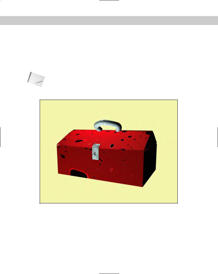
6.Drag the “Toolbox” material to the toolbox object and the “Hinge” material to the hinge and the handle.
Note Bump and glossiness mappings are not visible until the scene is rendered. To see the material’s results, choose Rendering Render and click the Render button.
Figure 22-34 shows the well-used toolbox.
Figure 22-34: This toolbox shows its age with Glossiness and Bump mappings.
Using the Map Path Utility
After you have all your maps in place, losing them can really make life troublesome. However, Max includes a utility that helps you determine which maps are missing and lets you edit the path to them to quickly and easily locate them. The Bitmap/Photometric Path Editor utility is available in the Utility panel. To find it, click on the More button and select Bitmap/Photometric Path Editor from the list of utilities.
Chapter 22 Adding Material Details with Maps |
635 |
Cross- |
This utility is used for bitmaps as well as photometric lights. You can learn about photometric |
Reference |
lights in Chapter 27, “Basic Lighting Techniques.” |
|
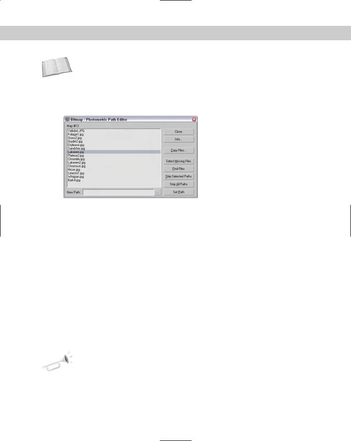
When opened, the Path Editor rollout includes the Edit Resources button that opens the Bitmap/Photometric Path Editor window, shown in Figure 22-35. The rollout also includes two options for displaying the Materials Editor and Material Library bitmap paths. The Close button closes the rollout.
Figure 22-35: The Bitmap/Photometric Path Editor window lets you alter map paths.
The Info button in the Bitmap/Photometric Path Editor dialog box lists all the nodes that use the selected map. The Copy Files button opens a File dialog in which you can select a location to copy the selected map to. The Select Missing Files option selects any maps in the list that can’t be located. The Find Files button lists the maps in the current selection that can be located and the number that are missing. Stripping paths removes the path information and leaves only the map name. The New Path field lets you enter the path information to apply to the selected maps. The button with three dots to the right of the New Path field lets you browse for a path, and the Set Path button applies the path designated in the New Path field to the selected maps.
Using Map Instances
Using the same bitmap for many different map channels is common. For example, you may use the same bitmap for the Diffuse and Bump map channels. If a file includes the same bitmaps over and over, the file size can increase and replacing a bitmap when you make changes can become difficult. This potential problem can be fixed easily by making the maps into instances instead of copies. If you have an existing Max file, you can use the Instance Duplicate Maps utility to find all the common maps and make them instances automatically.
New |
The Instance Duplicate Maps utility is new to 3ds max 6. |
Feature |
|
Access this utility from the Utilities menu in the Material Editor or from the Utilities panel. Both commands open the same dialog box, shown in Figure 22-36. From this dialog box, you can select which maps to make instances or click Instance All to consolidate all the found maps into instances.

636 Part IV Materials and Maps
Figure 22-36: The Instance Duplicate Maps dialog box lets you consolidate maps into a single instance.
Summary
We’ve covered lots of ground in this chapter because there are lots of different maps. Learning to use these maps will make a big difference in the realism of your materials.
In this chapter you learned about
All the different map types in several different categories, including 2D, 3D, Compositors, Color Mods, and Reflection/Refraction
The various mapping possibilities provided in the Maps rollout
How to use the Bitmap Path Editor to change map paths
Using the Duplicate Map Instances utility
In the next chapter, you gain some experience with mapping coordinates.
|
|
|

Controlling
Mapping
Coordinates
Throughout the modeling chapter as you created objects, the Generate Mapping Coordinates option appeared for almost all
objects. So now you finally get to find out what mapping coordinates are and how to use them.
Mapping coordinates are used to define how a texture map is aligned to an object. These coordinates are expressed using U, V, and W dimensions, with U being a horizontal direction, V being a vertical direction, and W being depth.
When you enable the Generate Mapping Coordinates option for new objects, Max takes its best guess at where these coordinates should be located. For example, a Box primitive applies a texture map to each face. This works well in some cases, but you won’t have to wait long until you’ll want to change the coordinates.
Control over the mapping coordinates is accomplished using many different modifiers, including the grand-daddy of them all — UVW Unwrap.
Mapping Modifiers
Among the many modifiers found in the Modifiers menu are several that are specific to material maps. These modifiers are mainly found in the UV Coordinates submenu and are used to define the coordinates for positioning material maps. These modifiers include the UVW Map, UVW Mapping Add, UVW Mapping Clear, UVW XForm, MapScaler (WSM), Unwrap UVW, Camera Map (WSM), and Camera Map. We also look at the Displace modifier found in the Parameteric Deformers menu because it deals with maps.
UVW Map modifier
The UVW Map modifier lets you specify the mapping coordinates for an object. Primitives, Loft Objects, and NURBS can generate their own mapping coordinates, but you need to use this modifier to apply mapping coordinates to mesh objects and patches.
23C H A P T E R
In This Chapter
Working with material modifiers
Applying labels with the UVW Map modifier
Using the Unwrap UVW modifier and the Edit UVW window
Deforming surfaces with the Displace modifier
638 Part IV Materials and Maps
Note Objects that create their own mapping coordinates apply them to Map Channel 1. If you apply the UVW Map modifier to Map Channel 1 of an object that already has mapping coordinates, then the applied coordinates overwrite the existing ones.
You can apply the UVW Map modifier to different map channels. Applying this modifier places a map gizmo on the object. You can move, scale, or rotate this gizmo. To transform a UVW Map gizmo, you must select it from the subobject list. Gizmos that are scaled smaller than the object can be tiled.
Many different types of mappings exist, and the parameter rollout for this modifier lets you select which one to use. The Length, Width, and Height values are the dimensions for the UVW Map gizmo. You can also set tiling values in all directions.
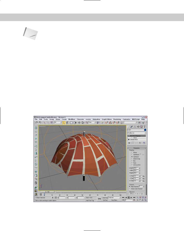
The Alignment section offers eight buttons for controlling the alignment of the gizmo. The Fit button fits the gizmo to the edges of the object. The Center button aligns the gizmo center with the object’s center. The Bitmap Fit button opens a File dialog box where you can align the gizmo to the resolution of the selected bitmaps. The Normal Align button lets you drag on the surface of the object, and when you release the mouse button, the gizmo origin is aligned with the normal. The View Align button aligns the gizmo to match the current viewport. The Region Fit button lets you drag a region in the viewport and match the gizmo to this region. The Reset button moves the gizmo to its original location. The Acquire button aligns the gizmo with the same coordinates as another object.
Figure 23-1 displays a brick map applied to an umbrella using spherical mapping.
Figure 23-1: The UVW Map modifier lets you specify various mapping coordinates for material maps.

Chapter 23 Controlling Mapping Coordinates |
639 |
Note
Tip
Tutorial: Using the UVW Map modifier to apply decals
After mapping coordinates have been applied either automatically or with the UVW Map modifier, you can use the UVW XForm modifier to move, rotate, and scale the mapping coordinates.
Most objects can automatically generate mapping coordinates — with the exception of meshes. For meshes, you need to use the UVW Map modifier. The UVW Map modifier includes seven different mapping options. Each mapping option wraps the map in a different way. The options include Planar, Cylindrical, Spherical, Shrink Wrap, Box, Face, and XYZ to UVW.
In this tutorial, we use the UVW Map modifier to apply a decal to a rocket model. Zygote Media created the rocket model.
To use the UVW Map modifier, follow these steps:
1.Open the Nasa decal on rocket.max file from the Chap 23 directory on the CD-ROM.
This file includes a model of a rocket with the appropriate materials applied. The Chap 23 directory on the CD-ROM also includes a 300×600 image of the word NASA in black capital letters on a white background. The background color of this image has been set to be transparent, and the image was saved as a .GIF.
The GIF format, typically used for Web pages, can easily make areas of the image transparent. These transparent areas become the alpha channel when loaded into Max.
2.Open the Material Editor (or press the M key), and select the first sample slot. Name the material NASA Logo. Click the Diffuse color swatch, and select a white color. Then click the map button to the right of the Diffuse color swatch, and from the Material/Map Browser, double-click the Bitmap map. Locate the NASA image from the Chap 23 directory on the CD-ROM, and click Open. The bitmap image loads, and the Bitmap parameters display in the rollouts. In the Coordinates rollout, enter a value of –90 in the W Angle field. The letters rotate vertically. Then, in the Bitmap Parameters rollout, select the Image Alpha option.
3.Select the lower white section of the rocket in the viewport, and open the Modify panel. At the top of the Modify panel, click the Modifier List and select the UVW Map modifier. Select the Cylindrical Mapping option, but don’t select the Cap option in the Parameters rollout.
4.With the cylinder section selected, open the Material Editor again, select the first sample slot, and click the Assign Material to Selection button.
When a bitmap is applied to an object using the UVW Map modifier, you can change the length, width, and tiling of the bitmap using the UVW Map manipulator. If you enable the Select and Manipulate button on the main toolbar the manipulator appears as green lines. When you move the mouse over the top of these green lines, they turn red, and you can drag them to alter the map dimensions. Use the small green circles at the edges of the map to change the tiling values. As you use the manipulator, the map is updated in real time within the viewports if you have enabled the Show Map in Viewport option in the Material Editor.
Figure 23-2 shows the resulting rendered image.
640 Part IV Materials and Maps
Figure 23-2: You can use the UVW Map modifier to apply decals to objects.
UVW Mapping Add and Clear modifiers
The UVW Mapping Add and the UVW Mapping Clear modifiers are added to the Modifier Stack when you add or clear a channel using the Channel Info utility. More on this utility is covered in Chapter 50, “Max and Games.”
UVW XForm modifier
The UVW XForm modifier enables you to adjust mapping coordinates. It can be applied to mapping coordinates that are automatically created or to mapping coordinates created with the UVW Map modifier. The parameter rollout includes values for the UVW Tile and UVW Offsets. You can also select the Map Channel to use.
Map Scaler modifier
The Map Scaler modifier is available as both an Object-Space modifier and a World-Space modifier. The World-Space version of this modifier maintains the size of all maps applied to an object if the object itself is resized. The Object-Space version ties the map to the object, so the map scales along with the object.
New |
The Object-Space Map Scaler modifier is new in 3ds max 6. |
Feature |
|

Chapter 23 Controlling Mapping Coordinates |
641 |
Camera Map modifier
The Camera Map modifier creates planar mapping coordinates based on the camera’s position. It comes in two flavors — one that is applied using Object-Space and another applied using World-Space.
The single parameter for this modifier is Pick Camera. To use this modifier, click the Pick Camera button and select a camera. The mapping coordinates are applied to the selected object.
Displace modifier
The Displace modifier can alter an object’s geometry by displacing elements using a Displace gizmo or a grayscale bitmap image (to create terrains, for example). The Displace gizmo can have one of four different shapes: Planar, Cylindrical, Spherical, or Shrink Wrap. Gizmos can be placed exterior to an object or inside an object to push it from within.
The Displace modifier parameters include Strength and Decay values. The Luminance Center value defines the center point for a grayscale bitmap. Buttons are available for Loading and Removing bitmaps and maps, and you can blur these objects with the Blur value. If a map is loaded, you can select and control its mapping coordinates. The final set of parameters lets you control the alignment of the bitmap or map. Figure 23-3 shows the effect of the Displace modifier on one side of a die.
Figure 23-3: You can use the Displace modifier as a modeling tool to change the surface of an object.

642 Part IV Materials and Maps
Tutorial: Creating an engraved wedding band
Chapter 13 includes some ring examples using the Bevel and Bevel Profile modifiers. This example shows another method for creating a ring and using the Displace modifier to add an engraving to it.
To create and engrave a ring with the Displace modifier, follow these steps:
1.Select Create Standard Primitives Torus and drag in the Top viewport to create a Torus object. Set its Radius 1 to 50, its Radius 2 to 12, and its Segments and Sides values to 200.
2.Select Modifiers Parametric Deformers Spherify to apply the Spherify modifier to the Torus object and set its Percent to 70. This creates a nice smooth ring.
3.Select Modifiers Parametric Deformers Displace and select the Cylindrical Map Type option. Click the Bitmap button. Double-click the Bitmap map type in the Material/Map Browser that opens, and then select the Special Someone.tif file from the Chap 23 directory. Set the Strength value to 0.5.
4.As a final step, right-click in the Modifier Stack and select Collapse All.
5.Figure 23-4 shows the resulting engraved ring.
Figure 23-4: You can use the Displace modifier to indent the surface of an object.