

- •Preface
- •About This Book
- •Acknowledgments
- •Contents at a Glance
- •Contents
- •Relaxing at the Beach
- •Dressing the Scene
- •Animating Motion
- •Rendering the Final Animation
- •Summary
- •The Interface Elements
- •Using the Menus
- •Using the Toolbars
- •Using the Viewports
- •Using the Command Panel
- •Using the Lower Interface Bar Controls
- •Interacting with the Interface
- •Getting Help
- •Summary
- •Understanding 3D Space
- •Using the Viewport Navigation Controls
- •Configuring the Viewports
- •Working with Viewport Backgrounds
- •Summary
- •Working with Max Scene Files
- •Setting File Preferences
- •Importing and Exporting
- •Referencing External Objects
- •Using the File Utilities
- •Accessing File Information
- •Summary
- •Customizing Modify and Utility Panel Buttons
- •Working with Custom Interfaces
- •Configuring Paths
- •Selecting System Units
- •Setting Preferences
- •Summary
- •Creating Primitive Objects
- •Exploring the Primitive Object Types
- •Summary
- •Selecting Objects
- •Setting Object Properties
- •Hiding and Freezing Objects
- •Using Layers
- •Summary
- •Cloning Objects
- •Understanding Cloning Options
- •Mirroring Objects
- •Cloning over Time
- •Spacing Cloned Objects
- •Creating Arrays of Objects
- •Summary
- •Working with Groups
- •Building Assemblies
- •Building Links between Objects
- •Displaying Links and Hierarchies
- •Working with Linked Objects
- •Summary
- •Using the Schematic View Window
- •Working with Hierarchies
- •Setting Schematic View Preferences
- •Using List Views
- •Summary
- •Working with the Transformation Tools
- •Using Pivot Points
- •Using the Align Commands
- •Using Grids
- •Using Snap Options
- •Summary
- •Exploring the Modifier Stack
- •Exploring Modifier Types
- •Summary
- •Exploring the Modeling Types
- •Working with Subobjects
- •Modeling Helpers
- •Summary
- •Drawing in 2D
- •Editing Splines
- •Using Spline Modifiers
- •Summary
- •Creating Editable Mesh and Poly Objects
- •Editing Mesh Objects
- •Editing Poly Objects
- •Using Mesh Editing Modifiers
- •Summary
- •Introducing Patch Grids
- •Editing Patches
- •Using Modifiers on Patch Objects
- •Summary
- •Creating NURBS Curves and Surfaces
- •Editing NURBS
- •Working with NURBS
- •Summary
- •Morphing Objects
- •Creating Conform Objects
- •Creating a ShapeMerge Object
- •Creating a Terrain Object
- •Using the Mesher Object
- •Working with BlobMesh Objects
- •Creating a Scatter Object
- •Creating Connect Objects
- •Modeling with Boolean Objects
- •Creating a Loft Object
- •Summary
- •Understanding the Various Particle Systems
- •Creating a Particle System
- •Using the Spray and Snow Particle Systems
- •Using the Super Spray Particle System
- •Using the Blizzard Particle System
- •Using the PArray Particle System
- •Using the PCloud Particle System
- •Using Particle System Maps
- •Controlling Particles with Particle Flow
- •Summary
- •Understanding Material Properties
- •Working with the Material Editor
- •Using the Material/Map Browser
- •Using the Material/Map Navigator
- •Summary
- •Using the Standard Material
- •Using Shading Types
- •Accessing Other Parameters
- •Using External Tools
- •Summary
- •Using Compound Materials
- •Using Raytrace Materials
- •Using the Matte/Shadow Material
- •Using the DirectX 9 Shader
- •Applying Multiple Materials
- •Material Modifiers
- •Summary
- •Understanding Maps
- •Understanding Material Map Types
- •Using the Maps Rollout
- •Using the Map Path Utility
- •Using Map Instances
- •Summary
- •Mapping Modifiers
- •Using the Unwrap UVW modifier
- •Summary
- •Working with Cameras
- •Setting Camera Parameters
- •Summary
- •Using the Camera Tracker Utility
- •Summary
- •Using Multi-Pass Cameras
- •Creating Multi-Pass Camera Effects
- •Summary
- •Understanding the Basics of Lighting
- •Getting to Know the Light Types
- •Creating and Positioning Light Objects
- •Viewing a Scene from a Light
- •Altering Light Parameters
- •Working with Photometric Lights
- •Using the Sunlight and Daylight Systems
- •Using Volume Lights
- •Summary
- •Selecting Advanced Lighting
- •Using Local Advanced Lighting Settings
- •Tutorial: Excluding objects from light tracing
- •Summary
- •Understanding Radiosity
- •Using Local and Global Advanced Lighting Settings
- •Working with Advanced Lighting Materials
- •Using Lighting Analysis
- •Summary
- •Using the Time Controls
- •Working with Keys
- •Using the Track Bar
- •Viewing and Editing Key Values
- •Using the Motion Panel
- •Using Ghosting
- •Animating Objects
- •Working with Previews
- •Wiring Parameters
- •Animation Modifiers
- •Summary
- •Understanding Controller Types
- •Assigning Controllers
- •Setting Default Controllers
- •Examining the Various Controllers
- •Summary
- •Working with Expressions in Spinners
- •Understanding the Expression Controller Interface
- •Understanding Expression Elements
- •Using Expression Controllers
- •Summary
- •Learning the Track View Interface
- •Working with Keys
- •Editing Time
- •Editing Curves
- •Filtering Tracks
- •Working with Controllers
- •Synchronizing to a Sound Track
- •Summary
- •Understanding Your Character
- •Building Bodies
- •Summary
- •Building a Bones System
- •Using the Bone Tools
- •Using the Skin Modifier
- •Summary
- •Creating Characters
- •Working with Characters
- •Using Character Animation Techniques
- •Summary
- •Forward versus Inverse Kinematics
- •Creating an Inverse Kinematics System
- •Using the Various Inverse Kinematics Methods
- •Summary
- •Creating and Binding Space Warps
- •Understanding Space Warp Types
- •Combining Particle Systems with Space Warps
- •Summary
- •Understanding Dynamics
- •Using Dynamic Objects
- •Defining Dynamic Material Properties
- •Using Dynamic Space Warps
- •Using the Dynamics Utility
- •Using the Flex Modifier
- •Summary
- •Using reactor
- •Using reactor Collections
- •Creating reactor Objects
- •Calculating and Previewing a Simulation
- •Constraining Objects
- •reactor Troubleshooting
- •Summary
- •Understanding the Max Renderers
- •Previewing with ActiveShade
- •Render Parameters
- •Rendering Preferences
- •Creating VUE Files
- •Using the Rendered Frame Window
- •Using the RAM Player
- •Reviewing the Render Types
- •Using Command-Line Rendering
- •Creating Panoramic Images
- •Getting Printer Help
- •Creating an Environment
- •Summary
- •Creating Atmospheric Effects
- •Using the Fire Effect
- •Using the Fog Effect
- •Summary
- •Using Render Elements
- •Adding Render Effects
- •Creating Lens Effects
- •Using Other Render Effects
- •Summary
- •Using Raytrace Materials
- •Using a Raytrace Map
- •Enabling mental ray
- •Summary
- •Understanding Network Rendering
- •Network Requirements
- •Setting up a Network Rendering System
- •Starting the Network Rendering System
- •Configuring the Network Manager and Servers
- •Logging Errors
- •Using the Monitor
- •Setting up Batch Rendering
- •Summary
- •Compositing with Photoshop
- •Video Editing with Premiere
- •Video Compositing with After Effects
- •Introducing Combustion
- •Using Other Compositing Solutions
- •Summary
- •Completing Post-Production with the Video Post Interface
- •Working with Sequences
- •Adding and Editing Events
- •Working with Ranges
- •Working with Lens Effects Filters
- •Summary
- •What Is MAXScript?
- •MAXScript Tools
- •Setting MAXScript Preferences
- •Types of Scripts
- •Writing Your Own MAXScripts
- •Learning the Visual MAXScript Editor Interface
- •Laying Out a Rollout
- •Summary
- •Working with Plug-Ins
- •Locating Plug-Ins
- •Summary
- •Low-Res Modeling
- •Using Channels
- •Using Vertex Colors
- •Rendering to a Texture
- •Summary
- •Max and Architecture
- •Using AEC Objects
- •Using Architectural materials
- •Summary
- •Tutorial: Creating Icy Geometry with BlobMesh
- •Tutorial: Using Caustic Photons to Create a Disco Ball
- •Summary
- •mental ray Rendering System
- •Particle Flow
- •reactor 2.0
- •Schematic View
- •BlobMesh
- •Spline and Patch Features
- •Import and Export
- •Shell Modifier
- •Vertex Paint and Channel Info
- •Architectural Primitives and Materials
- •Minor Improvements
- •Choosing an Operating System
- •Hardware Requirements
- •Installing 3ds max 6
- •Authorizing the Software
- •Setting the Display Driver
- •Updating Max
- •Moving Max to Another Computer
- •Using Keyboard Shortcuts
- •Using the Hotkey Map
- •Main Interface Shortcuts
- •Dialog Box Shortcuts
- •Miscellaneous Shortcuts
- •System Requirements
- •Using the CDs with Windows
- •What’s on the CDs
- •Troubleshooting
- •Index
718 Part VI Lighting
Using Local Advanced Lighting Settings
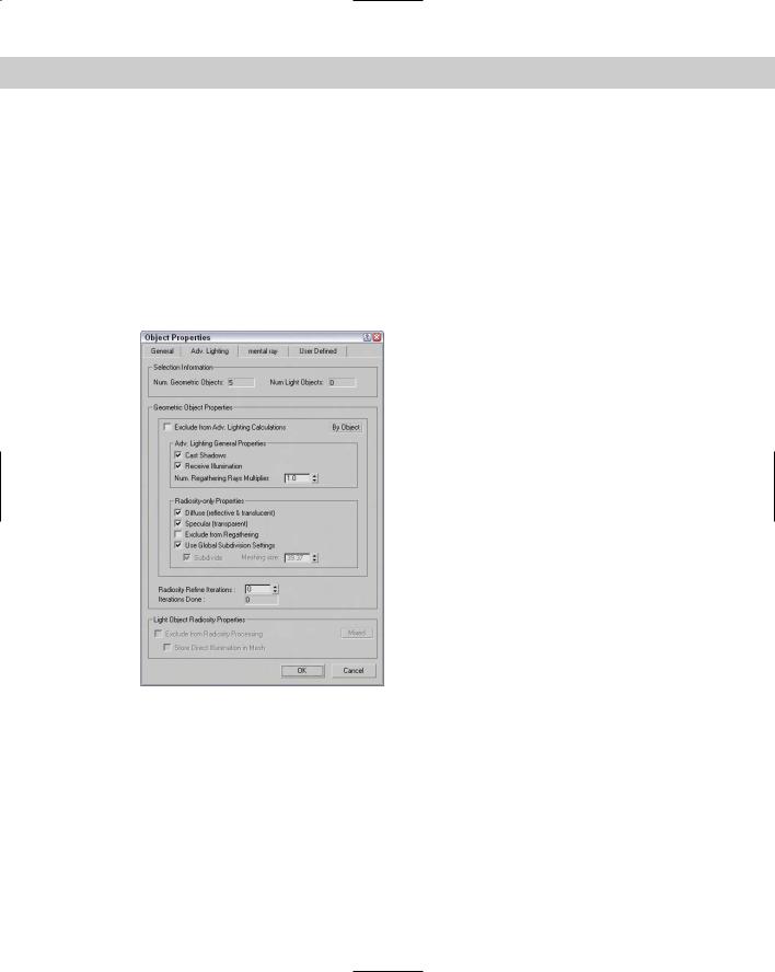
You can set advanced lighting settings locally for specific objects using the Object Properties dialog box, as shown in Figure 28-6.
At the top of the panel is the number of selected objects and lights. This dialog box lets you specify whether this object should be excluded from the advanced lighting calculations. The properties can be set By Object or By Layer. If included, you can select whether the object casts shadows, receives illumination, and how it handles Radiosity. The Number Regathering Rays Multiplier option sets the number of rays cast by the selected object. For large smooth surfaces, reducing artifacts by increasing this value can be helpful. The rest of the settings in this panel deal with Radiosity.
Figure 28-6: Use the Advanced Lighting panel in the Object Properties dialog box to disable advanced lighting.
Tutorial: Excluding objects from light tracing
Using the Object Properties dialog box, you can exclude certain objects from the light tracing calculations.
To exclude objects from the Light Tracer, follow these steps:
1.Open the Heated hotplate.max file from the Chap 28 directory on the CD-ROM. This file includes a simple model of a hotplate.
Chapter 28 Advanced Lighting and Light Tracing |
719 |
2.Open the Advanced Lighting panel by selecting Rendering Advanced Lighting Light Tracer (or press the 9 key). In the Parameters rollout, set the Bounces value to 2.
3.In the Front viewport, select the plug, cord, and floor objects, and then select Edit Object Properties to open the Properties dialog box for these objects. In the Object Properties dialog box, open the Advanced Lighting panel and enable the Exclude from Advanced Lighting Calculations option.
4.In the Render Scene dialog box, click the Render button. This renders the scene in the Rendered Frame Window.
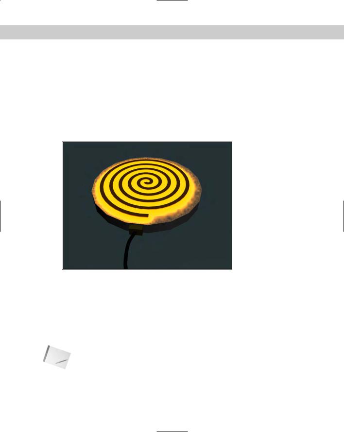
Figure 28-7 shows the scene rendered with advanced lighting that excludes certain objects.
Figure 28-7: Color bleeding becomes much stronger with a higher
Bounce value.
Working with the Advanced Lighting
Override Material
Applying an advanced lighting solution can have a direct impact on the materials in the scene. The Material Editor includes a material that is useful for working with advanced lighting: the Advanced Lighting Override material.
Note The Advanced Lighting Override material does not need to be applied to all objects that are to receive advanced lighting. It is used only to override the existing scene settings for certain materials.
720 Part VI Lighting
As an example of how this material can be used, consider the last example. Rather than excluding objects from the Advanced Lighting calculations, you can instead use the Light Tracer panel to set the global settings for the scene and apply the Advanced Lighting Override material to the hotplate coils with a higher Color Bleed value. This causes the coils to bleed, but not the rest of the scene.
Another common use for this material is to use the Luminance Scale value to cause selfilluminating materials to add light energy to the global illumination calculations.
The Advanced Lighting Override material type includes material parameters that override the Advanced Lighting solution. These parameters, shown in Figure 28-8, let you set the amount of Reflectance, Color Bleed, Transmittance, Luminance, and Indirect Light Bump Scale that the material uses.
Figure 28-8: The Advanced Lighting Override Material rollout defines how light interacts with the material.
Summary
Advanced lighting offers a new way to shine lights on your scenes. With these features, many new lighting options are available. Advanced lighting enables two global illumination methods: light tracing and radiosity. In this chapter, light tracing was the focus. This chapter covered the following topics:
Enabling advanced lighting
Discovering light tracing
Setting local advanced lighting settings
Using the Advanced Lighting Override material
In the next chapter, you dig deeper into advanced lighting by looking at radiosity.
|
|
|
Advanced Lighting
and Radiosity
If you thought that advanced lighting was covered already, then you’d be missing half the boat. Radiosity is a lighting solution that
is used to compute lighting solutions that are much more realistic than the standard lighting solution. The solution deals with the effect of light bouncing off objects and being reflected to the environment. As you start to learn and use Radiosity, you’ll quickly discover that it is a complex system that takes lots of tweaking to get just right.
Understanding Radiosity
Imagine a scene that includes an umbrella with a light source directly overhead. If you rendered the scene, the object caught in the umbrella’s shadow would be too dark to see clearly. To fix this situation, you would need to add some extra lights under the umbrella and set them to not cast shadows. Although this workaround provides the solution we want, it is interesting to note that in real-life, this isn’t the case.
The difference between the workaround and real life has to do with the effect of light energy being reflected (or bounced) off the lit objects. It is this phenomenon that allows me to look down the hall and see whether my children’s light is still on past bedtime. Even though I can’t see the light directly, I know it is on because of the light that reflects off the other walls.
Radiosity is a lighting algorithm that follows rays of light throughout the scene, and every time it strikes a surface, the light energy is reduced, but the light energy is bounced onto the surrounding faces. The number of bounces that are computed, the more realistic the lighting solution, but the longer it takes to compute. So, using radiosity, the objects under the umbrella are visible even if they are in the shadows.
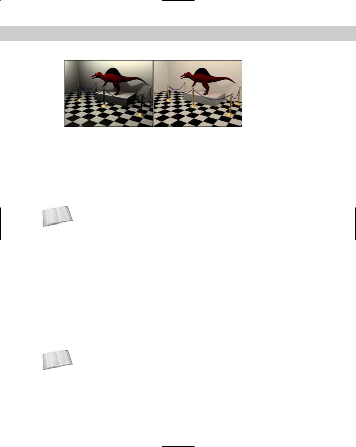
Radiosity is mostly used to light indoor scenes because that is where the effect of light bouncing is most evident. Radiosity, along with light tracing, is another method for computing global illumination. Figure 29-1 shows the dinosaur exhibit in a museum with and without radiosity. Notice how dark the shadows are in the normal lighting image.
29C H A P T E R
In This Chapter
Using advanced lighting
Understanding radiosity
Setting global advanced lighting parameters
Using the Lightscape material
722 Part VI Lighting
Figure 29-1: This scene is lighted using normal lighting (left) and radiosity lighting (right).
Lighting for Radiosity
The Advanced Lighting panel in Max includes light tracing and radiosity options. You can select either from the Advanced Lighting panel in the Render Scene dialog box. You can open this panel with the Radiosity option selected using the Rendering Advanced Lighting Radiosity menu command. Pressing the 9 key opens the Render Scene dialog box with the Advanced Lighting panel open.
Cross- |
Light tracing is covered in Chapter 28, “Advanced Lighting and Light Tracing.” |
Reference |
|
Radiosity lighting is not displayed until you have Max compute it by clicking the Start button in the Radiosity Processing Parameters rollout. After a radiosity solution is calculated, the results are saved as light maps. These maps are easy to apply to a scene and can be viewed within the viewports. However, when the geometry or lights of the scene change, you need to recalculate the lighting solution.
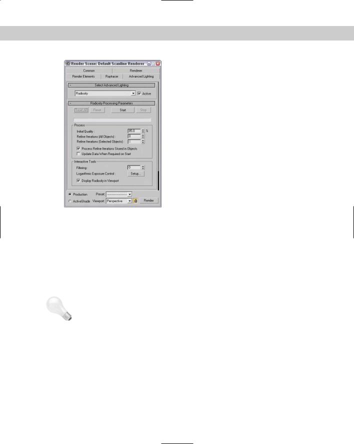
The Radiosity Processing Parameters rollout, shown in Figure 29-2, lets you set the quality of the radiosity solution. You can also specify the number of iterations to use for the scene and for the selected objects. These are different steps in the radiosity computation. The Initial Quality defines how accurate the rays that are bounced around the scene are. This stage sets the brightness for the scene. The Refine Iterations improves the general quality of the lighting solution for each iteration. You can refine iterations only for the selected object. This lets you target the iterations instead of computing them for the entire scene.
The Interactive Tools section lets you specify a Filtering value. A greater Filtering value eliminates noise between adjacent surfaces by averaging the lighting coming from all surrounding surfaces. The Setup button offers access to the Exposure Control rollout in the Environment panel. You can also turn off Radiosity in the viewports.
Cross- |
Chapter 41, “Rendering Basics,” includes coverage of the Exposure Control rollout. |
Reference |
|
Chapter 29 Advanced Lighting and Radiosity |
723 |
Figure 29-2: The Radiosity Processing Parameters rollout includes buttons for computing a solution.
|
Subdividing a mesh for radiosity |
|
As you begin to play with radiosity, you’ll quickly find that to get accurate results, you |
|
need to have good, clean models. If any models have long, thin faces, then the results are |
|
unpredictable. |
|
The Radiosity Meshing Parameters rollout includes an option to enable meshing and a |
|
Meshing Size value. This setting is the same as the Size value parameter for the Subdivide |
|
modifier, except that it is applied globally. |
Tip |
If you’re creating an indoor room using the Box object, be aware that Box objects have only |
|
one external face surface with normals, so the interior of a Box object will not have the cor- |
|
rect lighting. You can easily fix this by applying the Shell modifier to the Box object. This adds |
|
an interior set of faces to the Box object. |
Using the Subdivide modifier
The Modifiers menu includes a submenu for Radiosity modifiers. This submenu includes only the Subdivide modifier and a World-Space version of the Subdivide modifier. This modifier accomplishes a simple task — to create a mesh that has regular, equally shaped triangular faces that work well when computing a radiosity solution.
724 Part VI Lighting
Tip
Tip
Although this modifier was created to help with radiosity solutions, it also helps with other commands that require regular mesh faces such as the Boolean and Terrain compound objects.
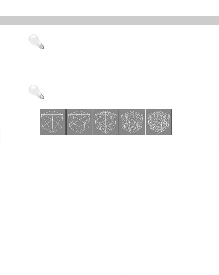
The Parameters rollout includes a Size value that determines the density of the mesh. The lower the value, the denser the mesh and the better the resulting radiosity solution, but the longer the solution takes. This same Subdivision Size setting can also be found (and set globally) in the Radiosity Meshing Parameters rollout of the Advanced Lighting panel. It is also found in the Advanced Lighting panel of the Object Properties dialog box. Figure 29-3 shows a simple cube with the Subdivide modifier applied and the Size value set to (from left to right) 50, 30, 25, 20, and 12.
If you drag the Size value, you’ll probably want to set the Update option to Manual or you’ll find yourself waiting while Max computes some seriously dense mesh, or you can just disable the Display Subdivision option.
Figure 29-3: The Subdivide modifier changes all mesh faces into regularly shaped triangular faces.
Tutorial: Preparing a mesh for radiosity
When it comes to meshes that have long, thin, and irregular faces, you don’t have to look any further than Boolean compound objects. These objects typically are divided along strange angles producing ugly meshes. The good news is that these meshes are easy to subdivide.
To subdivide an irregular mesh in preparation for a radiosity solution, follow these steps:
1.Open the Boolean object.max file from the Chap 29 directory on the CD-ROM.
This file includes two copies of a Box object with an arch shape Boolean subtracted from it.
2.Select the top object, and choose the Modifiers Radiosity Modifiers Subdivide menu command.
This applies the Subdivide modifier to the object.
3.In the Parameters rollout, select the Manual update option, set the Size value to 5.0, and click Update Now.
If the Display Subdivision option is enabled, then the changes are visible in the viewport.
4.Open the Advanced Lighting panel with the Rendering Advanced Lighting menu command (or press the 9 key). Select Radiosity from the drop-down menu.
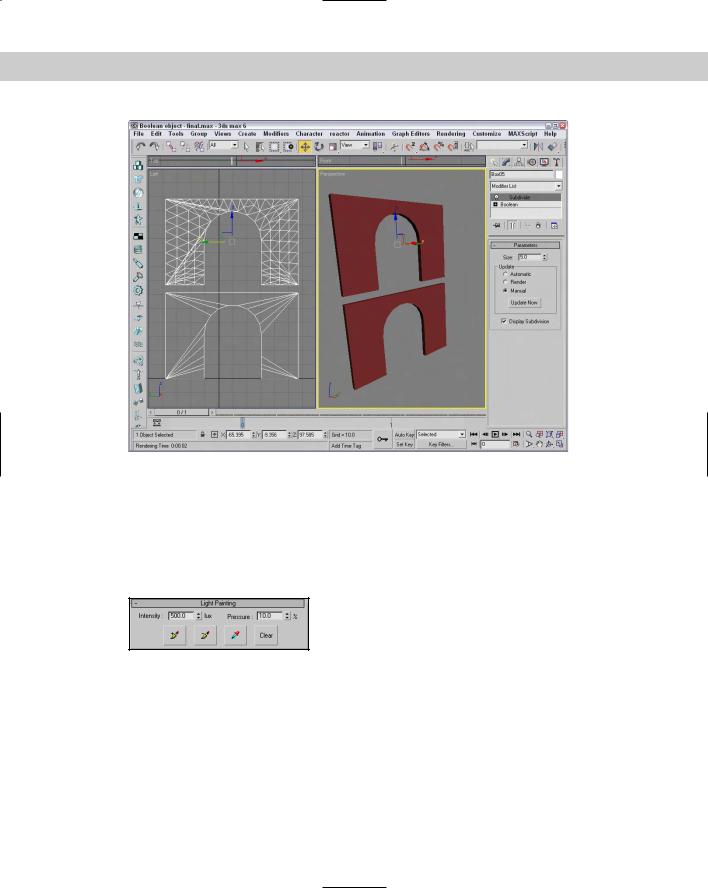
Figure 29-4 shows the two objects with and without the Subdivide modifier applied. The top object is ready for a radiosity solution.
Chapter 29 Advanced Lighting and Radiosity |
725 |
Figure 29-4: Subdividing an irregular mesh prepares it for radiosity lighting.
Painting with light
The Light Painting rollout (found in the Advanced Lighting panel of the Render Scene dialog box), shown in Figure 29-5, includes buttons for Adding Illumination, Subtracting Illumination, and Picking an Illumination value from the scene. Using these tools, you can paint lighting on the objects in the scene. The Clear button removes all the changes you’ve made using the Light Painting tool.
Figure 29-5: Because lighting is saved as a light map, you can add or subtract light from the scene using a brush tool.
Rendering parameters and statistics
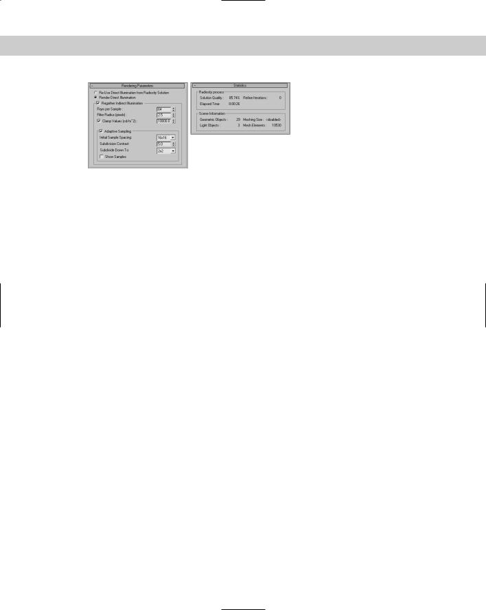
Settings in the Rendering Parameters rollout (shown in Figure 29-6) are used during the rendering process. The Re-Use and Use Direct Illumination options give you the chance to re-use the existing radiosity solution when rendering or to recalculate it as part of the rendering process. This can save some time during rendering.
The Regather Indirect Illumination option enables a Light-Tracer-like step along with the radiosity solution and produces an image that has the best of both solutions. The regathering options are the same as those defined for the light tracer.
The Statistics rollout includes information about the Radiosity process. Using this information, you can judge whether the settings are too high or too low.
726 Part VI Lighting
Figure 29-6: The Rendering Parameters and Statistics rollouts offer rendering options and statistics for radiosity solutions.
Tutorial: Lighting an archway with radiosity
Radiosity works best in indoor scenes or scenes that are mostly interior, so I’ve created a simple walkway with several archways. The only light source for this scene is an IES Sun light streaming in from the left.
To light an archway with Radiosity, follow these steps:
1.Open the Arch walkway.max file from the Chap 29 directory on the CD-ROM. This file includes a simple walkway made from primitives.
2.Open the Advanced Lighting panel with the Rendering Advanced Lighting menu command (or press the 9 key). Select Radiosity from the drop-down list in the Select Advanced Lighting rollout.
3.In the Radiosity Processing Parameters rollout, set the Refine Iterations value to 2 and click the Start button to have Max compute the radiosity solution.
4.In the Rendering Parameters rollout, enable the Render Direct Illumination, the Regather Indirect Illumination, and the Adaptive Sampling options.
Figure 29-7 shows the finished rendered walkway. Notice that all surfaces are well lit even though the scene has only a single light.