

- •Preface
- •About This Book
- •Acknowledgments
- •Contents at a Glance
- •Contents
- •Relaxing at the Beach
- •Dressing the Scene
- •Animating Motion
- •Rendering the Final Animation
- •Summary
- •The Interface Elements
- •Using the Menus
- •Using the Toolbars
- •Using the Viewports
- •Using the Command Panel
- •Using the Lower Interface Bar Controls
- •Interacting with the Interface
- •Getting Help
- •Summary
- •Understanding 3D Space
- •Using the Viewport Navigation Controls
- •Configuring the Viewports
- •Working with Viewport Backgrounds
- •Summary
- •Working with Max Scene Files
- •Setting File Preferences
- •Importing and Exporting
- •Referencing External Objects
- •Using the File Utilities
- •Accessing File Information
- •Summary
- •Customizing Modify and Utility Panel Buttons
- •Working with Custom Interfaces
- •Configuring Paths
- •Selecting System Units
- •Setting Preferences
- •Summary
- •Creating Primitive Objects
- •Exploring the Primitive Object Types
- •Summary
- •Selecting Objects
- •Setting Object Properties
- •Hiding and Freezing Objects
- •Using Layers
- •Summary
- •Cloning Objects
- •Understanding Cloning Options
- •Mirroring Objects
- •Cloning over Time
- •Spacing Cloned Objects
- •Creating Arrays of Objects
- •Summary
- •Working with Groups
- •Building Assemblies
- •Building Links between Objects
- •Displaying Links and Hierarchies
- •Working with Linked Objects
- •Summary
- •Using the Schematic View Window
- •Working with Hierarchies
- •Setting Schematic View Preferences
- •Using List Views
- •Summary
- •Working with the Transformation Tools
- •Using Pivot Points
- •Using the Align Commands
- •Using Grids
- •Using Snap Options
- •Summary
- •Exploring the Modifier Stack
- •Exploring Modifier Types
- •Summary
- •Exploring the Modeling Types
- •Working with Subobjects
- •Modeling Helpers
- •Summary
- •Drawing in 2D
- •Editing Splines
- •Using Spline Modifiers
- •Summary
- •Creating Editable Mesh and Poly Objects
- •Editing Mesh Objects
- •Editing Poly Objects
- •Using Mesh Editing Modifiers
- •Summary
- •Introducing Patch Grids
- •Editing Patches
- •Using Modifiers on Patch Objects
- •Summary
- •Creating NURBS Curves and Surfaces
- •Editing NURBS
- •Working with NURBS
- •Summary
- •Morphing Objects
- •Creating Conform Objects
- •Creating a ShapeMerge Object
- •Creating a Terrain Object
- •Using the Mesher Object
- •Working with BlobMesh Objects
- •Creating a Scatter Object
- •Creating Connect Objects
- •Modeling with Boolean Objects
- •Creating a Loft Object
- •Summary
- •Understanding the Various Particle Systems
- •Creating a Particle System
- •Using the Spray and Snow Particle Systems
- •Using the Super Spray Particle System
- •Using the Blizzard Particle System
- •Using the PArray Particle System
- •Using the PCloud Particle System
- •Using Particle System Maps
- •Controlling Particles with Particle Flow
- •Summary
- •Understanding Material Properties
- •Working with the Material Editor
- •Using the Material/Map Browser
- •Using the Material/Map Navigator
- •Summary
- •Using the Standard Material
- •Using Shading Types
- •Accessing Other Parameters
- •Using External Tools
- •Summary
- •Using Compound Materials
- •Using Raytrace Materials
- •Using the Matte/Shadow Material
- •Using the DirectX 9 Shader
- •Applying Multiple Materials
- •Material Modifiers
- •Summary
- •Understanding Maps
- •Understanding Material Map Types
- •Using the Maps Rollout
- •Using the Map Path Utility
- •Using Map Instances
- •Summary
- •Mapping Modifiers
- •Using the Unwrap UVW modifier
- •Summary
- •Working with Cameras
- •Setting Camera Parameters
- •Summary
- •Using the Camera Tracker Utility
- •Summary
- •Using Multi-Pass Cameras
- •Creating Multi-Pass Camera Effects
- •Summary
- •Understanding the Basics of Lighting
- •Getting to Know the Light Types
- •Creating and Positioning Light Objects
- •Viewing a Scene from a Light
- •Altering Light Parameters
- •Working with Photometric Lights
- •Using the Sunlight and Daylight Systems
- •Using Volume Lights
- •Summary
- •Selecting Advanced Lighting
- •Using Local Advanced Lighting Settings
- •Tutorial: Excluding objects from light tracing
- •Summary
- •Understanding Radiosity
- •Using Local and Global Advanced Lighting Settings
- •Working with Advanced Lighting Materials
- •Using Lighting Analysis
- •Summary
- •Using the Time Controls
- •Working with Keys
- •Using the Track Bar
- •Viewing and Editing Key Values
- •Using the Motion Panel
- •Using Ghosting
- •Animating Objects
- •Working with Previews
- •Wiring Parameters
- •Animation Modifiers
- •Summary
- •Understanding Controller Types
- •Assigning Controllers
- •Setting Default Controllers
- •Examining the Various Controllers
- •Summary
- •Working with Expressions in Spinners
- •Understanding the Expression Controller Interface
- •Understanding Expression Elements
- •Using Expression Controllers
- •Summary
- •Learning the Track View Interface
- •Working with Keys
- •Editing Time
- •Editing Curves
- •Filtering Tracks
- •Working with Controllers
- •Synchronizing to a Sound Track
- •Summary
- •Understanding Your Character
- •Building Bodies
- •Summary
- •Building a Bones System
- •Using the Bone Tools
- •Using the Skin Modifier
- •Summary
- •Creating Characters
- •Working with Characters
- •Using Character Animation Techniques
- •Summary
- •Forward versus Inverse Kinematics
- •Creating an Inverse Kinematics System
- •Using the Various Inverse Kinematics Methods
- •Summary
- •Creating and Binding Space Warps
- •Understanding Space Warp Types
- •Combining Particle Systems with Space Warps
- •Summary
- •Understanding Dynamics
- •Using Dynamic Objects
- •Defining Dynamic Material Properties
- •Using Dynamic Space Warps
- •Using the Dynamics Utility
- •Using the Flex Modifier
- •Summary
- •Using reactor
- •Using reactor Collections
- •Creating reactor Objects
- •Calculating and Previewing a Simulation
- •Constraining Objects
- •reactor Troubleshooting
- •Summary
- •Understanding the Max Renderers
- •Previewing with ActiveShade
- •Render Parameters
- •Rendering Preferences
- •Creating VUE Files
- •Using the Rendered Frame Window
- •Using the RAM Player
- •Reviewing the Render Types
- •Using Command-Line Rendering
- •Creating Panoramic Images
- •Getting Printer Help
- •Creating an Environment
- •Summary
- •Creating Atmospheric Effects
- •Using the Fire Effect
- •Using the Fog Effect
- •Summary
- •Using Render Elements
- •Adding Render Effects
- •Creating Lens Effects
- •Using Other Render Effects
- •Summary
- •Using Raytrace Materials
- •Using a Raytrace Map
- •Enabling mental ray
- •Summary
- •Understanding Network Rendering
- •Network Requirements
- •Setting up a Network Rendering System
- •Starting the Network Rendering System
- •Configuring the Network Manager and Servers
- •Logging Errors
- •Using the Monitor
- •Setting up Batch Rendering
- •Summary
- •Compositing with Photoshop
- •Video Editing with Premiere
- •Video Compositing with After Effects
- •Introducing Combustion
- •Using Other Compositing Solutions
- •Summary
- •Completing Post-Production with the Video Post Interface
- •Working with Sequences
- •Adding and Editing Events
- •Working with Ranges
- •Working with Lens Effects Filters
- •Summary
- •What Is MAXScript?
- •MAXScript Tools
- •Setting MAXScript Preferences
- •Types of Scripts
- •Writing Your Own MAXScripts
- •Learning the Visual MAXScript Editor Interface
- •Laying Out a Rollout
- •Summary
- •Working with Plug-Ins
- •Locating Plug-Ins
- •Summary
- •Low-Res Modeling
- •Using Channels
- •Using Vertex Colors
- •Rendering to a Texture
- •Summary
- •Max and Architecture
- •Using AEC Objects
- •Using Architectural materials
- •Summary
- •Tutorial: Creating Icy Geometry with BlobMesh
- •Tutorial: Using Caustic Photons to Create a Disco Ball
- •Summary
- •mental ray Rendering System
- •Particle Flow
- •reactor 2.0
- •Schematic View
- •BlobMesh
- •Spline and Patch Features
- •Import and Export
- •Shell Modifier
- •Vertex Paint and Channel Info
- •Architectural Primitives and Materials
- •Minor Improvements
- •Choosing an Operating System
- •Hardware Requirements
- •Installing 3ds max 6
- •Authorizing the Software
- •Setting the Display Driver
- •Updating Max
- •Moving Max to Another Computer
- •Using Keyboard Shortcuts
- •Using the Hotkey Map
- •Main Interface Shortcuts
- •Dialog Box Shortcuts
- •Miscellaneous Shortcuts
- •System Requirements
- •Using the CDs with Windows
- •What’s on the CDs
- •Troubleshooting
- •Index
1106 Part XI Compositing and Post-Production
Note If you don’t give the output event a name, the filename automatically becomes the event name.
Working with Ranges
The Range pane in the Video Post interface is found to the right of the Queue pane. It displays the ranges for each event. These turn red when selected. The beginning and end points of the range are marked with squares. You can move these points by dragging the squares. This moves the beginning and end points for all selected events.
Note Before you can move the ranges or drag the end points of a range, you need to select the Edit Range Bar button from the toolbar. The button is highlighted yellow when active.
When two or more events are selected, several additional buttons on the toolbar become enabled, including Swap Events, Align Selected Left, Align Selected Right, Make Selected Same Size, and Abut Selected. (Each of these buttons was shown earlier in Table 47-1.)
The Swap Events button is enabled only if two events are selected. When clicked, it changes the position of the two events. Because the order of the events is important, this can alter the final output.
The Align Selected Left and Align Selected Right buttons move the beginning or end points of every selected track until they line up with the first or last points of the top selected event.
The Make Selected Same Size button resizes any bottom events to be the same size as the top selected event. The Abut Selected button moves each selected event under the top event until its first point lines up with the last point of the selected event above it.
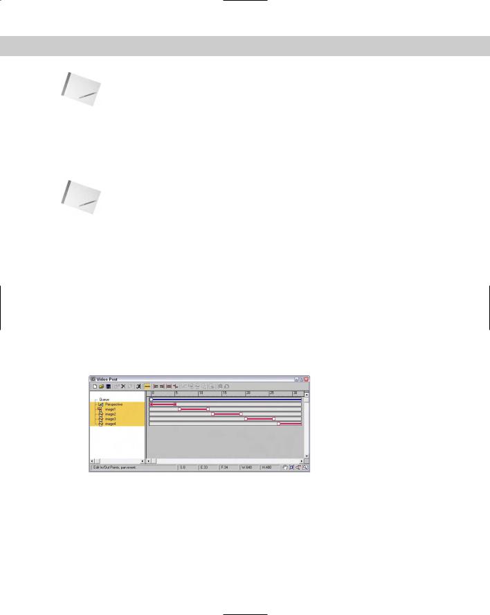
Figure 47-12 shows four image events that have been placed end-to-end using the Abut Selected button. Notice that the queue range spans the entire distance.
Figure 47-12: You can use the Abut Selected button to position several events end-to-end.
Working with Lens Effects Filters
The Add Image Filter Event dialog box’s drop-down list has several Lens Effects filters. These filters include Lens Effects Flare, Focus, Glow, and Highlight. Each of these filters is displayed and discussed in the sections that follow, but several parameters are common to all of them.
Chapter 47 Using the Video Post Interface 1107
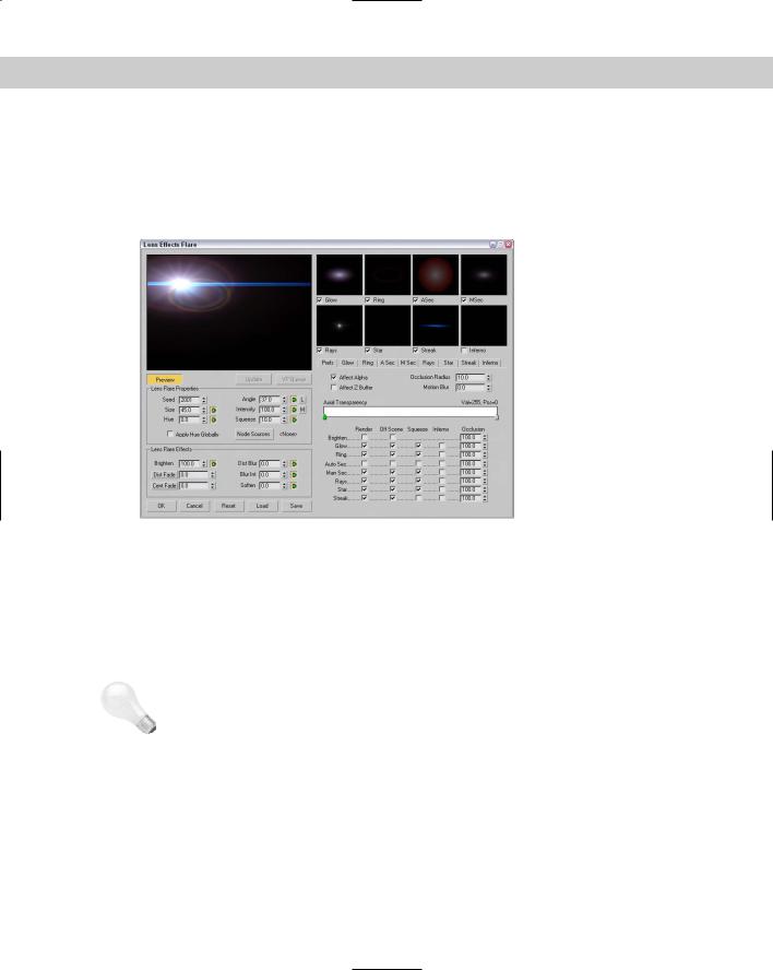
Many lens effects parameters in the various Lens Effects setup dialog boxes can be animated. These include Size, Hue, Angle, and Intensity. These are identified in the dialog boxes by green arrow buttons to the right of the parameter fields. These buttons work the way the Animate button in the main interface works. To animate a parameter, just click the corresponding arrow button, move the Time Slider to a new frame, and change the parameter. Figure 47-13 shows how these buttons look in the Lens Effects Flare dialog box.
|
Figure 47-13: Green arrow buttons in the Lens Effects Flare dialog |
|
box identify the parameters that can be animated for this effect. |
|
Each Lens Effects dialog box also includes a preview pane in the upper-left corner with three |
|
buttons underneath. Clicking the Preview button renders all enabled lens effects in the pre- |
|
view pane. The VP Queue button renders the current Video Post queue. Using the preview |
|
pane, you can get an idea of how the final output should look. With the Preview button |
|
enabled, any parameter changes in the dialog box are automatically updated in the preview |
|
pane. The Update button enables you to manually update the preview. You can right-click on |
|
the Preview pane to change its resolution for faster updates at lower resolutions. |
Tip |
If the VP Queue button is enabled, then a default Lens Effects image is displayed. Using this |
|
image, you can play around with the various settings while the Preview mode is enabled to |
|
gain an idea of what the various settings do. |
|
You can save the settings in each Lens Effect dialog box as a separate file that can be recalled |
|
at any time. These saved files have an .LZF extension and can be saved and loaded with the |
|
Save and Load buttons at the bottom left of the dialog box. |
|
Adding flares |
|
The Lens Effects Flare dialog box includes controls for adding flares of various types to an |
|
image. This dialog box includes a main preview pane and several smaller preview panes for |
|
each individual effect. The check boxes below these smaller preview panes let you enable or |
|
disable these smaller panes. |
1108 Part XI Compositing and Post-Production
Under the main preview pane are several global commands, and to their right is a series of tabbed panels that contain the settings for each individual effect type. The first panel is labeled Prefs and sets which effects are rendered (on and off scene), squeezed, which have the Inferno noise filter applied, and an Occlusion setting.
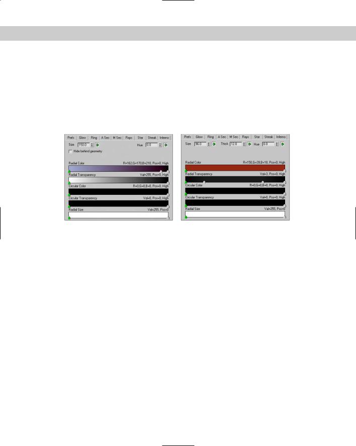
The settings for the individual flare types are included in the subsequent tabbed panels. They include Glow, Ring, A Sec, M Sec, Rays, Star, Streak, and Inferno. These tabbed panels include gradient color bars for defining the Radial Color, Radial Transparency, Circular Color, Circular Transparency, and Radial Size. Each of these tabbed panels has different settings, but Figure 47-14 shows the tabbed panels for the Glow and Ring effects.
Figure 47-14: The Glow and Ring tabbed panels are representative of all the different lens effect settings.
The gradient colors found in these tabbed panels are controlled by flags that appear under the gradient band. Double-clicking a flag opens a Color Selector dialog box where you can select a new color. Dragging these flags moves the gradient color. You can add a new flag to the band by clicking under the gradient away from the existing flags. The active flag is colored green. To delete flags, select them and press the Delete key. By right-clicking on the gradient band, you can access a pop-up menu of options that let you access several options for the selected gradient color. You can even load and save gradients. Gradients are saved as files with the .DGR extension.
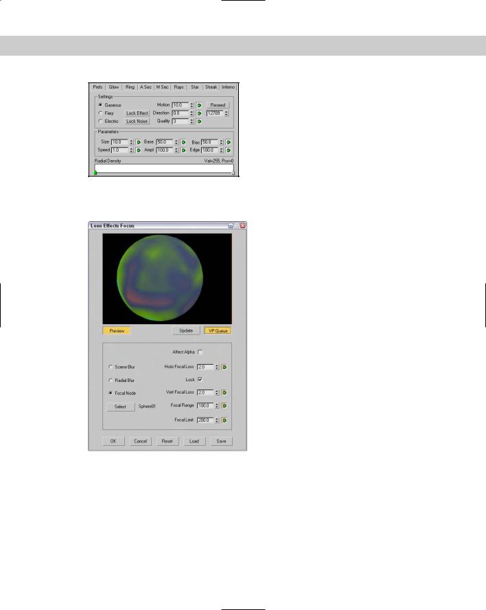
The right-most tabbed panel, shown in Figure 47-15, is labeled Inferno and provides a way to add noise to any of the effects. The Prefs tabbed panel includes a check box for enabling the Inferno settings for each effect. Inferno noise can be set to three different states: Gaseous, Fiery, and Electric. If your effect is looking too perfect, you can add some randomness to it with the Inferno option.
Adding focus
The Lens Effects Focus dialog box, shown in Figure 47-16, includes options for adding Scene Blur, Radial Blur, and Focal Node effects. If the Focal Node option is selected, you can click the Select button to open the Select Focal Object dialog box in order to choose the object that sets the focal point for the scene.
Chapter 47 Using the Video Post Interface 1109
Figure 47-15: The Inferno tabbed panel includes options for enabling noise for the various flare effects.
Figure 47-16: You can use the Lens Effects
Focus dialog box to blur an image.
You can also set values for the Horizontal Focal Loss and Vertical Focal Loss or enable the Lock button to lock these two parameters together. The Focal Range and Focal Limit values determine the distance from the focal point where the blurring begins or reaches full strength. You can also set the blurring to affect the Alpha channel.
1110 Part XI Compositing and Post-Production
Adding glow
The Lens Effects Glow dialog box, shown in Figure 47-17, enables you to apply glows to the entire scene or to specific objects based on the Object ID or Effects ID. Other Source options include Unclamped, Surf Norm (Surface Normals), Mask, Alpha, Z High, and Z Lo. This dialog box also enables you to Filter the glow, using options such as Edge, Perimeter Alpha, Perimeter, Bright, and Hue.
Additional tabbed panels under the preview pane let you control the Preferences, Gradients, and Inferno settings. In the Preferences tabbed panel, you can set the color of the glow to be based on the Gradient tabbed panel–defined gradients, based on Pixel or a User-defined color. You can also set the Intensity in the Preference tabbed panel.
Figure 47-17: Use the Lens Effects Glow dialog box to make objects and scenes glow.
Adding highlights
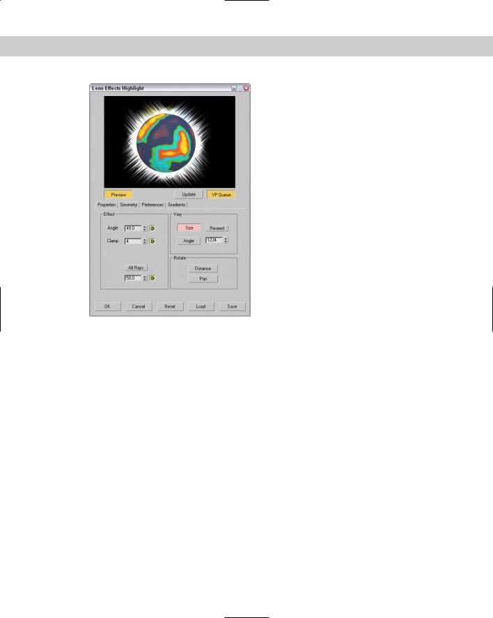
The Lens Effects Highlight dialog box, shown in Figure 47-18, includes the same Properties, Preferences, and Gradient tabbed panels as the Glow dialog box, except that the effects it produces are highlights instead of glows. The Geometry tabbed panel includes options for setting the Size and Angle of the highlights and how they rotate away from the highlighted object.
Chapter 47 Using the Video Post Interface 1111
Figure 47-18: Use the Lens Effects Highlight dialog box to add highlights to scene objects.
Tutorial: Making a halo shine
When it comes to glowing objects, I think of radioactive materials, celestial objects like comets and meteors, and heavenly objects like angels. In this tutorial, I’m leaning toward heaven in an attempt to create some glory. But because I couldn’t locate an angel, we use a simple halo.
To add highlights to a halo using the Video Post interface, follow these steps:
1.Open the Glowing halo.max file from the Chap 47 directory on the CD-ROM.
This file contains a head model and a halo. The halo object has been set to the G-Buffer Object Channel of 1 in its Object Properties dialog box.
2.Choose Rendering Video Post to open the Video Post interface. Click the Add Scene Event button on the toolbar.
The Add Scene Event dialog box appears.
3.Type a name for the event in the Label text field, and click OK. The event is added to the Queue pane.
4.Click the Add Image Filter Event button on the toolbar to open the associated dialog box. Select Lens Effects Highlight from the drop-down list, and click the Setup button.
The Lens Effects Highlight dialog box appears.

1112 Part XI Compositing and Post-Production
5.Click the VP Queue button followed by the Preview button to see the rendered scene. In the Properties tabbed panel, select the Object ID option and set the Object ID to 1 to match the G-Buffer channel for the halo object. In the Filter section, enable the All option. In the Preferences tabbed panel, set the Size to 3.0, Points to 4, the Color option to Pixel, and Intensity to 100. Then click OK.
6.Click the Execute Sequence button on the toolbar, and then click Render in the Execute Video Post dialog box.
Figure 47-19 shows the completed halo in all its shining glory.
Figure 47-19: Using the Lens Effects Highlight dialog box, you can add shining highlights to objects like this halo.
Adding backgrounds and filters using Video Post
As an example of the Video Post interface in action, we composite a background image of a waterfall with a rendered scene of an airplane model created by Viewpoint Datalabs. We then add some filter effects before producing the final output image.
To composite an image with the Video Post interface, follow these steps:
1.Open the Airplane over waterfall.max file from the Chap 47 directory on the CD-ROM.
This file includes an airplane model. The directory also includes an image called waterfall.tif that is used later.
2.Open the Video Post interface by choosing Rendering Video Post.
3.Add a background image to the queue by clicking the Add Image Input Event button. Click the Files button. Locate the waterfall.tif image from the Chap 47 directory on the CD-ROM, and click OK. Then click OK again to exit the Add Image Input Event dialog box.