

- •Preface
- •About This Book
- •Acknowledgments
- •Contents at a Glance
- •Contents
- •Relaxing at the Beach
- •Dressing the Scene
- •Animating Motion
- •Rendering the Final Animation
- •Summary
- •The Interface Elements
- •Using the Menus
- •Using the Toolbars
- •Using the Viewports
- •Using the Command Panel
- •Using the Lower Interface Bar Controls
- •Interacting with the Interface
- •Getting Help
- •Summary
- •Understanding 3D Space
- •Using the Viewport Navigation Controls
- •Configuring the Viewports
- •Working with Viewport Backgrounds
- •Summary
- •Working with Max Scene Files
- •Setting File Preferences
- •Importing and Exporting
- •Referencing External Objects
- •Using the File Utilities
- •Accessing File Information
- •Summary
- •Customizing Modify and Utility Panel Buttons
- •Working with Custom Interfaces
- •Configuring Paths
- •Selecting System Units
- •Setting Preferences
- •Summary
- •Creating Primitive Objects
- •Exploring the Primitive Object Types
- •Summary
- •Selecting Objects
- •Setting Object Properties
- •Hiding and Freezing Objects
- •Using Layers
- •Summary
- •Cloning Objects
- •Understanding Cloning Options
- •Mirroring Objects
- •Cloning over Time
- •Spacing Cloned Objects
- •Creating Arrays of Objects
- •Summary
- •Working with Groups
- •Building Assemblies
- •Building Links between Objects
- •Displaying Links and Hierarchies
- •Working with Linked Objects
- •Summary
- •Using the Schematic View Window
- •Working with Hierarchies
- •Setting Schematic View Preferences
- •Using List Views
- •Summary
- •Working with the Transformation Tools
- •Using Pivot Points
- •Using the Align Commands
- •Using Grids
- •Using Snap Options
- •Summary
- •Exploring the Modifier Stack
- •Exploring Modifier Types
- •Summary
- •Exploring the Modeling Types
- •Working with Subobjects
- •Modeling Helpers
- •Summary
- •Drawing in 2D
- •Editing Splines
- •Using Spline Modifiers
- •Summary
- •Creating Editable Mesh and Poly Objects
- •Editing Mesh Objects
- •Editing Poly Objects
- •Using Mesh Editing Modifiers
- •Summary
- •Introducing Patch Grids
- •Editing Patches
- •Using Modifiers on Patch Objects
- •Summary
- •Creating NURBS Curves and Surfaces
- •Editing NURBS
- •Working with NURBS
- •Summary
- •Morphing Objects
- •Creating Conform Objects
- •Creating a ShapeMerge Object
- •Creating a Terrain Object
- •Using the Mesher Object
- •Working with BlobMesh Objects
- •Creating a Scatter Object
- •Creating Connect Objects
- •Modeling with Boolean Objects
- •Creating a Loft Object
- •Summary
- •Understanding the Various Particle Systems
- •Creating a Particle System
- •Using the Spray and Snow Particle Systems
- •Using the Super Spray Particle System
- •Using the Blizzard Particle System
- •Using the PArray Particle System
- •Using the PCloud Particle System
- •Using Particle System Maps
- •Controlling Particles with Particle Flow
- •Summary
- •Understanding Material Properties
- •Working with the Material Editor
- •Using the Material/Map Browser
- •Using the Material/Map Navigator
- •Summary
- •Using the Standard Material
- •Using Shading Types
- •Accessing Other Parameters
- •Using External Tools
- •Summary
- •Using Compound Materials
- •Using Raytrace Materials
- •Using the Matte/Shadow Material
- •Using the DirectX 9 Shader
- •Applying Multiple Materials
- •Material Modifiers
- •Summary
- •Understanding Maps
- •Understanding Material Map Types
- •Using the Maps Rollout
- •Using the Map Path Utility
- •Using Map Instances
- •Summary
- •Mapping Modifiers
- •Using the Unwrap UVW modifier
- •Summary
- •Working with Cameras
- •Setting Camera Parameters
- •Summary
- •Using the Camera Tracker Utility
- •Summary
- •Using Multi-Pass Cameras
- •Creating Multi-Pass Camera Effects
- •Summary
- •Understanding the Basics of Lighting
- •Getting to Know the Light Types
- •Creating and Positioning Light Objects
- •Viewing a Scene from a Light
- •Altering Light Parameters
- •Working with Photometric Lights
- •Using the Sunlight and Daylight Systems
- •Using Volume Lights
- •Summary
- •Selecting Advanced Lighting
- •Using Local Advanced Lighting Settings
- •Tutorial: Excluding objects from light tracing
- •Summary
- •Understanding Radiosity
- •Using Local and Global Advanced Lighting Settings
- •Working with Advanced Lighting Materials
- •Using Lighting Analysis
- •Summary
- •Using the Time Controls
- •Working with Keys
- •Using the Track Bar
- •Viewing and Editing Key Values
- •Using the Motion Panel
- •Using Ghosting
- •Animating Objects
- •Working with Previews
- •Wiring Parameters
- •Animation Modifiers
- •Summary
- •Understanding Controller Types
- •Assigning Controllers
- •Setting Default Controllers
- •Examining the Various Controllers
- •Summary
- •Working with Expressions in Spinners
- •Understanding the Expression Controller Interface
- •Understanding Expression Elements
- •Using Expression Controllers
- •Summary
- •Learning the Track View Interface
- •Working with Keys
- •Editing Time
- •Editing Curves
- •Filtering Tracks
- •Working with Controllers
- •Synchronizing to a Sound Track
- •Summary
- •Understanding Your Character
- •Building Bodies
- •Summary
- •Building a Bones System
- •Using the Bone Tools
- •Using the Skin Modifier
- •Summary
- •Creating Characters
- •Working with Characters
- •Using Character Animation Techniques
- •Summary
- •Forward versus Inverse Kinematics
- •Creating an Inverse Kinematics System
- •Using the Various Inverse Kinematics Methods
- •Summary
- •Creating and Binding Space Warps
- •Understanding Space Warp Types
- •Combining Particle Systems with Space Warps
- •Summary
- •Understanding Dynamics
- •Using Dynamic Objects
- •Defining Dynamic Material Properties
- •Using Dynamic Space Warps
- •Using the Dynamics Utility
- •Using the Flex Modifier
- •Summary
- •Using reactor
- •Using reactor Collections
- •Creating reactor Objects
- •Calculating and Previewing a Simulation
- •Constraining Objects
- •reactor Troubleshooting
- •Summary
- •Understanding the Max Renderers
- •Previewing with ActiveShade
- •Render Parameters
- •Rendering Preferences
- •Creating VUE Files
- •Using the Rendered Frame Window
- •Using the RAM Player
- •Reviewing the Render Types
- •Using Command-Line Rendering
- •Creating Panoramic Images
- •Getting Printer Help
- •Creating an Environment
- •Summary
- •Creating Atmospheric Effects
- •Using the Fire Effect
- •Using the Fog Effect
- •Summary
- •Using Render Elements
- •Adding Render Effects
- •Creating Lens Effects
- •Using Other Render Effects
- •Summary
- •Using Raytrace Materials
- •Using a Raytrace Map
- •Enabling mental ray
- •Summary
- •Understanding Network Rendering
- •Network Requirements
- •Setting up a Network Rendering System
- •Starting the Network Rendering System
- •Configuring the Network Manager and Servers
- •Logging Errors
- •Using the Monitor
- •Setting up Batch Rendering
- •Summary
- •Compositing with Photoshop
- •Video Editing with Premiere
- •Video Compositing with After Effects
- •Introducing Combustion
- •Using Other Compositing Solutions
- •Summary
- •Completing Post-Production with the Video Post Interface
- •Working with Sequences
- •Adding and Editing Events
- •Working with Ranges
- •Working with Lens Effects Filters
- •Summary
- •What Is MAXScript?
- •MAXScript Tools
- •Setting MAXScript Preferences
- •Types of Scripts
- •Writing Your Own MAXScripts
- •Learning the Visual MAXScript Editor Interface
- •Laying Out a Rollout
- •Summary
- •Working with Plug-Ins
- •Locating Plug-Ins
- •Summary
- •Low-Res Modeling
- •Using Channels
- •Using Vertex Colors
- •Rendering to a Texture
- •Summary
- •Max and Architecture
- •Using AEC Objects
- •Using Architectural materials
- •Summary
- •Tutorial: Creating Icy Geometry with BlobMesh
- •Tutorial: Using Caustic Photons to Create a Disco Ball
- •Summary
- •mental ray Rendering System
- •Particle Flow
- •reactor 2.0
- •Schematic View
- •BlobMesh
- •Spline and Patch Features
- •Import and Export
- •Shell Modifier
- •Vertex Paint and Channel Info
- •Architectural Primitives and Materials
- •Minor Improvements
- •Choosing an Operating System
- •Hardware Requirements
- •Installing 3ds max 6
- •Authorizing the Software
- •Setting the Display Driver
- •Updating Max
- •Moving Max to Another Computer
- •Using Keyboard Shortcuts
- •Using the Hotkey Map
- •Main Interface Shortcuts
- •Dialog Box Shortcuts
- •Miscellaneous Shortcuts
- •System Requirements
- •Using the CDs with Windows
- •What’s on the CDs
- •Troubleshooting
- •Index
878 Part VIII Character Animation
Figure 35-7 shows the man with his bone links. Bones are created at the pivot point of each child object. To see the difference between the bones system and no bones, select the Select and Move button and try to move the head object off the man. As a bone object, it cannot move away from the body.
Figure 35-7: A linked primitive man after his objects were made into bones
Using the Skin Modifier
Unless you like working with skeletons, a bones system typically will have a skin attached to it. Any mesh can be made into a skin using the Skin modifier. With a skin attached to a bones system, you can move the bones system and the skin follows.
Skin modifier
The Skin modifier is useful for creating skin to surround a bones system. Each object with the Skin modifier applied gets a capsule-shaped envelope attached to it. When two of these envelopes overlap, their surfaces blend together like skin around a bone joint. These envelopes can be attached to NURBS, meshes, patches, bones, or even splines.
The Parameters rollout includes an Edit Envelopes button that places you in a special mode that lets you change the envelope for each bone. Within Edit Envelopes mode, the object is colored blue to show the areas where the envelope is within the object and red where the envelope is outside of the object. Using these visual clues, you can easily edit the envelopes to the desired effect. Once edited, you can copy and paste envelopes to other bones.

Chapter 35 Rigging Characters 879
Each bone that the modifier is applied to is listed in the Parameters rollout. You can Add and Remove Bones, Add and Remove Bone Cross Sections, and control the position and size of the Envelopes. There are also settings to weight the various vertices. The Skin modifier also includes three unique deformer gizmos that can be used to control how the skin bends at the joint, bulges, and morphs over an animation sequence.
The Skin modifier is one of the keys to character animation. The ability to control a system of bones using inverse kinematics would not be very beneficial without the ability to cover the bones with a skin. You can apply the Skin modifier to an object or a group of objects using the Modifier List or Modifiers Animation Modifiers Skin.
Skin subobjects
The single subobject available for the Skin modifier is Envelope. An Envelope is an area that surrounds the bone that defines which vertices of the Skin object are to be moved with the bone. In Envelope subobject mode, you can edit the size and influence of the envelope.
Editing envelopes
The Parameters rollout includes a list of bones that are assigned to the Skin modifier. You can add and remove bones from this list using the Add Bone and Remove Bone buttons below the list. The Edit Envelope button enters a mode where you can edit the envelope of the selected bone in the list. The Edit Envelope button works the same as clicking the Envelope subobject in the Modifier Stack.
Figure 35-8 shows a simple loft object surrounding three bone objects with a Skin modifier applied. The Add Bone button was used to include the three bones within the Skin modifier list. The first bone was selected within the list, and the Edit Envelope button was clicked, revealing the envelope for the first bone.
For each envelope, you can add a cross section using the Add Cross Section button. This button lets you select a cross-section shape within the viewports. The Remove Cross Section button removes an added cross section from the envelope.
When the envelope is visible within the viewport, the envelope consists of two capsuleshaped areas within each other. At either end of these areas are four small square handles that can be dragged to change the cross-section radius. The cross-section area changes to pink when selected. The radius of the selected cross section is displayed in the Radius field within the Envelope Properties section of the Parameters rollout.
The viewport shades red vertices on the skin surface that are included with the envelope and shades blue vertices that aren’t included within the envelope. These colors are visual clues that help you to see exactly which sections of the skin will move with the bones.
The preceding figure shows a modified envelope for the first bone. Notice that the size of the envelope has been increased. This was done by dragging on the cross-section handles. Also notice that the entire top section of the object is shaded red, indicating that the skin will move with the bone.
The Envelope Properties section of the Parameters rollout includes five icon buttons, shown in Table 35-1. The first toggles between Absolute and Relative. All vertices that fall within the outer envelope are fully weighted when the Absolute toggle is set, but only those within both envelopes are fully weighted when the Relative toggle is selected.
880 Part VIII Character Animation
Figure 35-8: Envelopes define which Skin vertices move with the underlying bone.
|
|
Table 35-1: Envelope Properties |
|
|
|
|
Button |
Description |
|
|
|
|
|
Toggles between Absolute and Relative |
|
|
Makes envelopes visible even when not selected |
|
|
Sets Falloff curve |
|
|
Copies envelope settings |
|
|
Pastes envelope settings |
|
|
|
The second icon button enables envelopes to be visible even when not selected. This helps you see how adjacent bones overlap. The third icon button sets the Falloff curve for the envelopes. The options within this flyout are Fast Out, Slow Out, Linear, and Sinual. The last
Chapter 35 Rigging Characters 881
two icon buttons can be used to Copy and Paste envelope settings to other bones. The flyout options for the Paste button include Paste (to a single bone), Paste to All Bones, and Paste to Multiple Bones (which opens a selection dialog box).
The Squash value determines the amount of squash applied to the object.
Working with weights
Working with the various envelopes and all their controls can be tricky. The Select section can limit the controls that you can select. Options include Vertices, Envelopes, and Cross Sections.
The Absolute Effect field lets you specify a weight value for the selected bone or vertices. The Rigid option makes the selected vertices move only with the closest bone. The Rigid Handles causes the handles of the selected vertices to move only with the closest bone. The Normalize option requires that all the weights assigned to the selected vertices add up to 1.0.
The Include and Exclude Vertices buttons let you remove the selected vertices from those being affected by the selected bone. The Select Exclude Verts button selects all excluded vertices.
Using the Weight Table
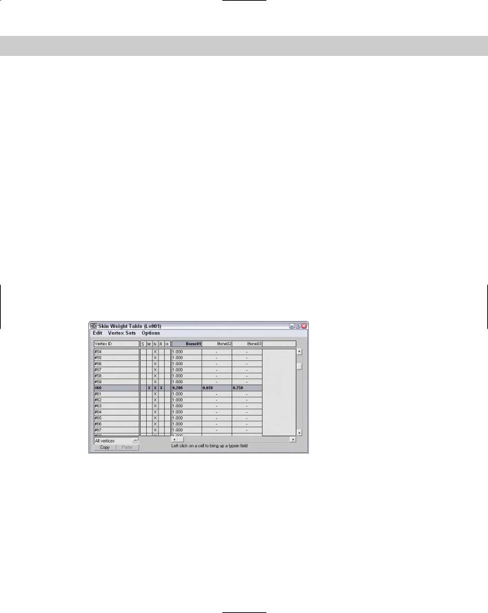
The Weight Table button opens the Weight Table interface, shown in Figure 35-9. This table displays all the vertices for the skinned object by ID in a column on the left side of the interface. All bones are listed in a row along the top. For each vertex and bone, you can set a weight.
Figure 35-9: The Weight Table lets you specify weight values for each vertex and for each bone.
The Edit menu includes commands to Copy and Paste weights. It also includes commands to Select All, Invert, and None. A selection of vertices can be combined into a Vertex Set and named. The Vertex Sets menu lets you create and delete these sets.
The Options menu lets you flip the interface so that bones are displayed in the first column and the vertex IDs are along the top row. The Update On Mouse Up option limits the updates until the mouse is released. Several options for showing and hiding interface elements are
882 Part VIII Character Animation
included. The Show Affected Bones option lists only the bones that are affected. The Show Attributes option displays a column of attributes labeled S, M, N, R, and H. The Show Exclusions option makes a check box available in each cell. When checked, the vertex is excluded. The Show Global option makes a drop-down list available that enables you to set an attribute for all vertices. The Show Locks option (like the Show Exclusions option) makes a check box available for each cell. Enabling this check box (the left one) locks the weight so it can’t change. The Set Sets UI makes available two buttons for creating and deleting vertex sets.
The S attribute is marked if a vertex is selected, the M attribute marks a vertex weight that has been modified, the N attribute marks a normalized weight, the R attribute marks rigid vertices, and an H attribute marks a vertex with rigid handles.
To set a weight, just locate the vertex for the bone, click in the cell, and type the new value. If you click on a cell and drag to the left or right, the weight value changes. Weight values can be dragged between cells. Right-clicking on a cell sets its value to 0, and right-clicking with the Ctrl key held down sets its value to 1.0.
After the vertex weights are set, you can click the Bake Selected Vertices to lock down the weight values. Changes to envelopes do not affect baked vertices.
Painting weights
Another way to assign whether vertices in the skin move with the bone is to assign weights to the vertices. Using the Paint Weights button, you can paint with a brush over the surface of the skin object. The Paint Strength value sets the value of each brush stroke. This value can be positive (up to 1.0) for vertices that will move with the bone or negative (to –1.0) for vertices that will not move with the bone. The Radius and Feather settings define the size and softness of the brush.
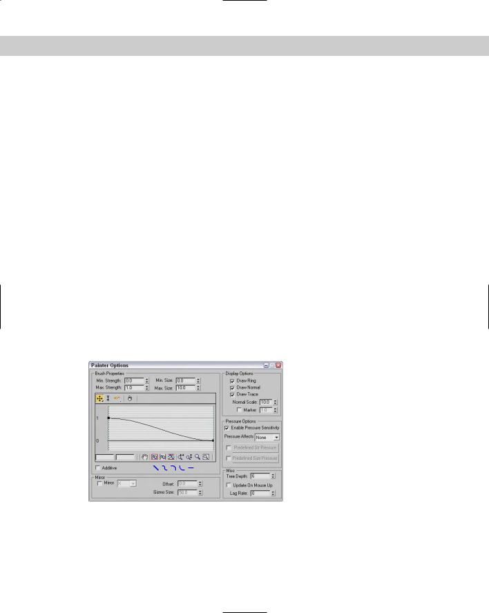
To the right of the Paint Weights button is the Painter Options button (it actually only has three dots on it), which opens the Painter Options dialog box, shown in Figure 35-10.
Figure 35-10: The Painter Options dialog box includes settings for controlling the size and sensitivity of the brush strokes.
Chapter 35 Rigging Characters 883
The Min/Max Strength and Min/Max Size values determine the minimum and maximum weight values and paint gizmo sizes. You can define the brush falloff using the curve. This keeps the weights from making an abrupt change (muscles tend to look funny when this happens). Under the curve are several buttons for quickly defining the shape of the falloff curve, including Linear, Smooth, Slow, Fast, and Flat.
The Display Options section includes options that determine the look of the painting gizmo. The Draw Ring, Normal, and Trace options make a ring; the surface normal or an arrow showing the trace direction appears. The Normal can be scaled, and the Marker option displays a small circular marker at the end of the normal.
You can enable Pressure Sensitivity for the brush gizmo. The options include None, Strength, Size, and Both. Using the graph, you can predefine Strength and Size pressure curves and then select to use them.
The Mirror option paints symmetrically on the opposite side of the gizmo across the specified axis. You can also set an Offset and the Gizmo Size. This is handy for muscles that you want to deform symmetrically. The Tree Depth, Update on Mouse Up, and Lag Rate options control how often the scene and the painted strokes are updated.
Mirror settings
Most characters have a natural symmetry, and you can use this symmetry to mirror envelopes and vertex weights between different sides of a model. You can use this feature by clicking the Mirror Mode button in the Mirror Parameters rollout. This button is active only when the Edit Envelope button is active.
New |
The Mirror Parameters rollout for the Skin modifier is new in 3ds max 6. |
Feature |
|
In Mirror Mode, you see an orange plane gizmo that marks the symmetrical line for the model. You can move and orient this plane using the Mirror Offset and Mirror Plane controls. Once oriented, Max computes the matching vertices based on the volumes from the mirror plane. All vertices on one half of the character appear blue, and all the matching vertices appear green. All vertices that cannot be matched appear red.
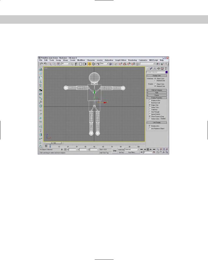
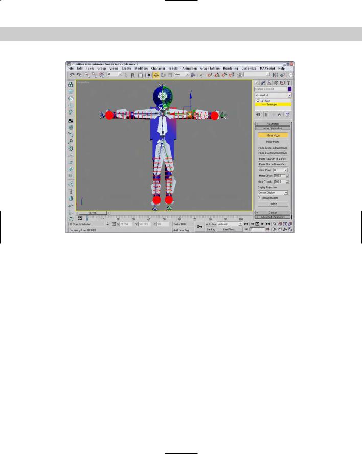
Figure 35-11 shows the primitive man object with a simple bones system positioned behind him. The Mirror Plane is positioned in the center of the character, and the bones and vertices on either side are colored green and blue.
If you drag over bones or vertices in the viewports, you can select them. Clicking the Mirror Paste button pastes the envelopes and vertex weights of the selected vertices to their matches. Or you can select the Paste Green to Blue Bones button or one of its neighbors to copy all the green bones or vertices to their matches, or vice versa.
The Display Projection drop-down list projects the position of the selected vertices onto the Mirror Plane so you can compare their locations relative to each other. With lots of vertices in your skin, you want to enable the Manual Update, or the viewport refreshes become slow.
884 Part VIII Character Animation
Figure 35-11: In Mirror Mode, matched bones and vertices appear green and blue.
Display and Advanced settings
The Display rollout controls which features are visible within the viewports. Options include Show Color Vertices, Show Colored Faces, Show All Envelopes, Show All Vertices, Show All Gizmos, Show No Envelopes, and Draw On Top Cross Sections and Draw On Top Envelopes.
The Advanced Parameters rollout includes an option to Back Transform Vertices. This option avoids applying transform keys to the skin because the bones control the motion. The Rigid Vertices and Rigid Patch Handles options set the vertices so that they are controlled by only one bone. This rollout also includes buttons for resetting vertices and bones. It also includes buttons for saving and loading envelopes. The envelopes are saved as files with the .ENV extension.
Tutorial: Applying the Skin modifier to a character
For this example, we create a bones system for a model and then apply and work with the Skin modifier. Viewpoint Datalabs provided this future man model that we can practice with.
To apply the Skin modifier to a future man model, follow these steps:
1.Open the Future man with skin.max file from the Chap 35 directory on the CD-ROM.
This file includes a futuristic man model with all his parts linked together. The linking was done way back in Chapter 9 as part of the Schematic View chapter.
Chapter 35 Rigging Characters 885
2.The first step is to create a bones system for the man. Before creating the bones system, press the H key to open the Select Objects dialog box and enable the Display Subtree option to see the hierarchy of this model. Now try to create a bones system that matches this linked structure.
3.Select Create Systems Bones IK Chain button. Click on the torso and again where it meets the pelvis, and then create two more bones for the right leg and boot. Right-click to end the bones chain. Click again on the torso, follow the left leg, and repeat for the two arms and head. Right-click in the active viewport to exit bone creation mode when finished.
4.Select all the parts that make up the future man mesh (without any of the bones), and choose Modifiers Animation Modifiers Skin to apply the Skin modifier.
5.In the Parameters rollout, click the Add button. The Select Bones dialog box opens. Click the All button to select all the bones, and click Select.
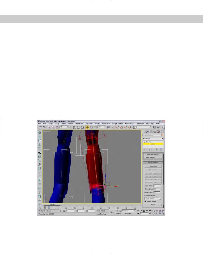
6.In the Parameters rollout, select ‘Bone04’ in the list and click the Edit Envelopes button. Zoom in on the highlighted bone (which is the left shin bone), select the cross-section handles for this bone, and set the Radius values to 0.15 (near the body) and 0.1 for the other end.
Figure 35-12 shows the resulting envelope for one of the bones.
Figure 35-12: Increasing the envelope to encompass the entire leg ensures that the entire leg moves with the bones.