

- •Preface
- •About This Book
- •Acknowledgments
- •Contents at a Glance
- •Contents
- •Relaxing at the Beach
- •Dressing the Scene
- •Animating Motion
- •Rendering the Final Animation
- •Summary
- •The Interface Elements
- •Using the Menus
- •Using the Toolbars
- •Using the Viewports
- •Using the Command Panel
- •Using the Lower Interface Bar Controls
- •Interacting with the Interface
- •Getting Help
- •Summary
- •Understanding 3D Space
- •Using the Viewport Navigation Controls
- •Configuring the Viewports
- •Working with Viewport Backgrounds
- •Summary
- •Working with Max Scene Files
- •Setting File Preferences
- •Importing and Exporting
- •Referencing External Objects
- •Using the File Utilities
- •Accessing File Information
- •Summary
- •Customizing Modify and Utility Panel Buttons
- •Working with Custom Interfaces
- •Configuring Paths
- •Selecting System Units
- •Setting Preferences
- •Summary
- •Creating Primitive Objects
- •Exploring the Primitive Object Types
- •Summary
- •Selecting Objects
- •Setting Object Properties
- •Hiding and Freezing Objects
- •Using Layers
- •Summary
- •Cloning Objects
- •Understanding Cloning Options
- •Mirroring Objects
- •Cloning over Time
- •Spacing Cloned Objects
- •Creating Arrays of Objects
- •Summary
- •Working with Groups
- •Building Assemblies
- •Building Links between Objects
- •Displaying Links and Hierarchies
- •Working with Linked Objects
- •Summary
- •Using the Schematic View Window
- •Working with Hierarchies
- •Setting Schematic View Preferences
- •Using List Views
- •Summary
- •Working with the Transformation Tools
- •Using Pivot Points
- •Using the Align Commands
- •Using Grids
- •Using Snap Options
- •Summary
- •Exploring the Modifier Stack
- •Exploring Modifier Types
- •Summary
- •Exploring the Modeling Types
- •Working with Subobjects
- •Modeling Helpers
- •Summary
- •Drawing in 2D
- •Editing Splines
- •Using Spline Modifiers
- •Summary
- •Creating Editable Mesh and Poly Objects
- •Editing Mesh Objects
- •Editing Poly Objects
- •Using Mesh Editing Modifiers
- •Summary
- •Introducing Patch Grids
- •Editing Patches
- •Using Modifiers on Patch Objects
- •Summary
- •Creating NURBS Curves and Surfaces
- •Editing NURBS
- •Working with NURBS
- •Summary
- •Morphing Objects
- •Creating Conform Objects
- •Creating a ShapeMerge Object
- •Creating a Terrain Object
- •Using the Mesher Object
- •Working with BlobMesh Objects
- •Creating a Scatter Object
- •Creating Connect Objects
- •Modeling with Boolean Objects
- •Creating a Loft Object
- •Summary
- •Understanding the Various Particle Systems
- •Creating a Particle System
- •Using the Spray and Snow Particle Systems
- •Using the Super Spray Particle System
- •Using the Blizzard Particle System
- •Using the PArray Particle System
- •Using the PCloud Particle System
- •Using Particle System Maps
- •Controlling Particles with Particle Flow
- •Summary
- •Understanding Material Properties
- •Working with the Material Editor
- •Using the Material/Map Browser
- •Using the Material/Map Navigator
- •Summary
- •Using the Standard Material
- •Using Shading Types
- •Accessing Other Parameters
- •Using External Tools
- •Summary
- •Using Compound Materials
- •Using Raytrace Materials
- •Using the Matte/Shadow Material
- •Using the DirectX 9 Shader
- •Applying Multiple Materials
- •Material Modifiers
- •Summary
- •Understanding Maps
- •Understanding Material Map Types
- •Using the Maps Rollout
- •Using the Map Path Utility
- •Using Map Instances
- •Summary
- •Mapping Modifiers
- •Using the Unwrap UVW modifier
- •Summary
- •Working with Cameras
- •Setting Camera Parameters
- •Summary
- •Using the Camera Tracker Utility
- •Summary
- •Using Multi-Pass Cameras
- •Creating Multi-Pass Camera Effects
- •Summary
- •Understanding the Basics of Lighting
- •Getting to Know the Light Types
- •Creating and Positioning Light Objects
- •Viewing a Scene from a Light
- •Altering Light Parameters
- •Working with Photometric Lights
- •Using the Sunlight and Daylight Systems
- •Using Volume Lights
- •Summary
- •Selecting Advanced Lighting
- •Using Local Advanced Lighting Settings
- •Tutorial: Excluding objects from light tracing
- •Summary
- •Understanding Radiosity
- •Using Local and Global Advanced Lighting Settings
- •Working with Advanced Lighting Materials
- •Using Lighting Analysis
- •Summary
- •Using the Time Controls
- •Working with Keys
- •Using the Track Bar
- •Viewing and Editing Key Values
- •Using the Motion Panel
- •Using Ghosting
- •Animating Objects
- •Working with Previews
- •Wiring Parameters
- •Animation Modifiers
- •Summary
- •Understanding Controller Types
- •Assigning Controllers
- •Setting Default Controllers
- •Examining the Various Controllers
- •Summary
- •Working with Expressions in Spinners
- •Understanding the Expression Controller Interface
- •Understanding Expression Elements
- •Using Expression Controllers
- •Summary
- •Learning the Track View Interface
- •Working with Keys
- •Editing Time
- •Editing Curves
- •Filtering Tracks
- •Working with Controllers
- •Synchronizing to a Sound Track
- •Summary
- •Understanding Your Character
- •Building Bodies
- •Summary
- •Building a Bones System
- •Using the Bone Tools
- •Using the Skin Modifier
- •Summary
- •Creating Characters
- •Working with Characters
- •Using Character Animation Techniques
- •Summary
- •Forward versus Inverse Kinematics
- •Creating an Inverse Kinematics System
- •Using the Various Inverse Kinematics Methods
- •Summary
- •Creating and Binding Space Warps
- •Understanding Space Warp Types
- •Combining Particle Systems with Space Warps
- •Summary
- •Understanding Dynamics
- •Using Dynamic Objects
- •Defining Dynamic Material Properties
- •Using Dynamic Space Warps
- •Using the Dynamics Utility
- •Using the Flex Modifier
- •Summary
- •Using reactor
- •Using reactor Collections
- •Creating reactor Objects
- •Calculating and Previewing a Simulation
- •Constraining Objects
- •reactor Troubleshooting
- •Summary
- •Understanding the Max Renderers
- •Previewing with ActiveShade
- •Render Parameters
- •Rendering Preferences
- •Creating VUE Files
- •Using the Rendered Frame Window
- •Using the RAM Player
- •Reviewing the Render Types
- •Using Command-Line Rendering
- •Creating Panoramic Images
- •Getting Printer Help
- •Creating an Environment
- •Summary
- •Creating Atmospheric Effects
- •Using the Fire Effect
- •Using the Fog Effect
- •Summary
- •Using Render Elements
- •Adding Render Effects
- •Creating Lens Effects
- •Using Other Render Effects
- •Summary
- •Using Raytrace Materials
- •Using a Raytrace Map
- •Enabling mental ray
- •Summary
- •Understanding Network Rendering
- •Network Requirements
- •Setting up a Network Rendering System
- •Starting the Network Rendering System
- •Configuring the Network Manager and Servers
- •Logging Errors
- •Using the Monitor
- •Setting up Batch Rendering
- •Summary
- •Compositing with Photoshop
- •Video Editing with Premiere
- •Video Compositing with After Effects
- •Introducing Combustion
- •Using Other Compositing Solutions
- •Summary
- •Completing Post-Production with the Video Post Interface
- •Working with Sequences
- •Adding and Editing Events
- •Working with Ranges
- •Working with Lens Effects Filters
- •Summary
- •What Is MAXScript?
- •MAXScript Tools
- •Setting MAXScript Preferences
- •Types of Scripts
- •Writing Your Own MAXScripts
- •Learning the Visual MAXScript Editor Interface
- •Laying Out a Rollout
- •Summary
- •Working with Plug-Ins
- •Locating Plug-Ins
- •Summary
- •Low-Res Modeling
- •Using Channels
- •Using Vertex Colors
- •Rendering to a Texture
- •Summary
- •Max and Architecture
- •Using AEC Objects
- •Using Architectural materials
- •Summary
- •Tutorial: Creating Icy Geometry with BlobMesh
- •Tutorial: Using Caustic Photons to Create a Disco Ball
- •Summary
- •mental ray Rendering System
- •Particle Flow
- •reactor 2.0
- •Schematic View
- •BlobMesh
- •Spline and Patch Features
- •Import and Export
- •Shell Modifier
- •Vertex Paint and Channel Info
- •Architectural Primitives and Materials
- •Minor Improvements
- •Choosing an Operating System
- •Hardware Requirements
- •Installing 3ds max 6
- •Authorizing the Software
- •Setting the Display Driver
- •Updating Max
- •Moving Max to Another Computer
- •Using Keyboard Shortcuts
- •Using the Hotkey Map
- •Main Interface Shortcuts
- •Dialog Box Shortcuts
- •Miscellaneous Shortcuts
- •System Requirements
- •Using the CDs with Windows
- •What’s on the CDs
- •Troubleshooting
- •Index

482 Part III Modeling
5.Now select the letter B in the logo name, and click the ShapeMerge button again. Use the Pick Shape button and the Cookie Cutter operation option to remove the centers of this letter. Click the Select Object button on the main toolbar to exit ShapeMerge mode. Repeat this step for each of the letters that has an interior portion, including the following letters: g, e, a, d, o, a, and e.
6.Open the Display panel again, and in the Hide rollout, click Unhide All to redisplay the interior splines of the letter B that make up the bug’s left eye. Hold down the Ctrl key, select the two splines, choose Modifiers Mesh Editing Extrude, and enter an Amount value of 0.0.
Figure 17-7 shows the finished logo. Notice that the letters have the interior sections removed.
Figure 17-7: The logo with the interior centers removed from extruded letters using the ShapeMerge object
Creating a Terrain Object
The Terrain object is a great object that enables you to create terrains from splines representing elevation contours. These contour splines can be created in Max or imported using a format like AutoCAD’s DWG. If the splines are created in Max, make sure that they are attached to each other as one object, in the order in which they will eventually be attached. The splines all need to be closed splines.
Chapter 17 Building Compound Objects 483
To create a terrain, create splines at varying elevations, select all the splines, and click the Terrain button. You can use the Pick Operand button in the Pick Operand rollout to select additional splines to add to the Terrain object. All splines in the object become operands and are displayed in the Operands list.
The Form group includes three options that determine how the terrain is formed: Graded Surface, Graded Solid, and Layered Solid. The Graded Surface option displays a surface grid over the contour splines; the Graded Solid adds a bottom to the object; and the Layered Solid displays each contour as a flat, terraced area.
The Display group includes options to display the Terrain mesh, the Contour lines, or Both. You can also specify how you want to update the terrain.
The Simplification rollout lets you alter the resolution of the terrain by selecting how many vertical and horizontal vertices to use. Options include using all vertices, half of the vertices, a quarter of the vertices, twice the vertices, or four times the vertices.
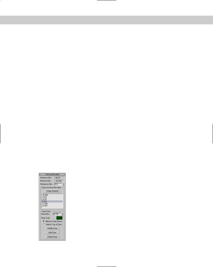
Coloring elevations
The Color by Elevation rollout, shown in Figure 17-8, displays as reference the Maximum and Minimum Elevations. Between these is a Reference Elevation value, which is the location where the landmass meets the water. Entering a Reference Elevation and clicking the Create Defaults button automatically creates several separate color zones. You can add, modify, or delete zones using the Add, Modify, or Delete Zone buttons.
You can access each color zone from a list. To change a zone’s color, select it and click the color swatch. You can set colors to Blend to the Color Above or to be Solid to Top of Zone.
Tutorial: Creating an island with the Terrain compound object
In this tutorial, we create a simple island. The Color by Elevation rollout makes distinguishing the water from the land easy.
Figure 17-8: The Color by Elevation rollout lets you change the color for different elevations.
484 Part III Modeling
To create an island using the Terrain object, follow these steps:
1.Select Create Shapes Ellipse and drag in the Top view to create several ellipses of various sizes representing the contours of the island. The first ellipse you create should be the largest, and they should get progressively smaller.
2.In the Left view, select and move the ellipses up and down so that the largest one is on the bottom and the smallest one is on top. You can create two smaller hills by including two ellipses at the same level.
3.Use the Edit Select All (Ctrl+A) menu command to select all the ellipses, and select Create Compound Terrain.
The ellipses automatically join together. Joining all the ellipses forms the island.
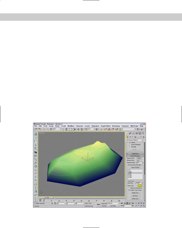
4.In the Color by Elevation rollout, select a Reference Elevation of 5 and click the Create Defaults button.
This automatically creates color zones for the island. The elevation values for each zone are displayed in a list within the Color by Elevation rollout. Selecting an elevation value in the list displays its color in the color swatch.
5.Select each elevation value individually, and set all Zones to Blend to the Color Above option for all zones, except for the Zone with the lightest blue.
This creates a distinct break between the sea and the land of the island.
Figure 17-9 shows the final terrain. In an example later in this chapter, we use the Scatter compound object to add trees to the small terrain island.
Figure 17-9: A Terrain island created with the Terrain compound object

Chapter 17 Building Compound Objects 485
Using the Mesher Object
You can use the Mesher compound object to convert objects to mesh objects on the fly as an animation progresses. This feature is useful for objects such as particle systems. After you convert the object to a mesh object, you can apply modifiers that weren’t possible before, such as Optimize, UVW Map, and others.
Another benefit of the Mesher object is that you can apply several complex modifiers to a single Mesher object and tie it to a particle system rather than applying the modifiers to all the pieces that make up a particle system.
The Parameters rollout of the Mesher object includes a Pick Object button. Click this button, and select an object in the viewport to make the selected object an instance of the Mesher object. This action does not delete the original object, and the Mesher instance is oriented to the Mesher object’s coordinate system. The object name then appears on the button. You can change the object by clicking the button again and selecting a new object.
Caution |
Do not delete the original object, or the Mesher instance also disappears. If you want to |
|
render only the Mesher instance, then select the original object and hide it using the Tools |
|
Display Floater command. |
The Time Offset is the number of the frames ahead (values can be negative) or behind the original object the animation should progress. If the Build Only at Render Time option is set, then the Mesher instance is not visible in the viewports but shows up in the final rendered image. You can use the Update button to manually force an update of the Mesher instance after the settings for the original object have been modified.
When you use the Mesher object to create an instance of a particle system, the bounding box of the particle system as it streams the particles becomes long and thin over time. This long and thin bounding box can potentially cause problems with certain modifiers. You can prevent these problems by selecting an alternative bounding box that doesn’t change over time. To select a new bounding box, select the Custom Bounding Box option, click the Pick Bounding Box button, and click an object in the viewport. You can select the original object as the new bounding box. With the Mesher object selected, the bounding box is shown in orange wherever it is located. The corner coordinates of the custom bounding box are displayed under the Pick Bounding Box button.
Note |
Mesher objects can also be used as Particle Flow events using the Add and Remove buttons |
|
at the bottom of the Parameters rollout. |
Figure 17-10 shows a Super Spray particle system on the right and its Mesher instance with the Bend modifier applied on the left.
Cross- |
Chapter 18, “Creating Particles and Particle Flow,” provides more information on working |
Reference |
with particle systems. |
|