

- •Preface
- •About This Book
- •Acknowledgments
- •Contents at a Glance
- •Contents
- •Relaxing at the Beach
- •Dressing the Scene
- •Animating Motion
- •Rendering the Final Animation
- •Summary
- •The Interface Elements
- •Using the Menus
- •Using the Toolbars
- •Using the Viewports
- •Using the Command Panel
- •Using the Lower Interface Bar Controls
- •Interacting with the Interface
- •Getting Help
- •Summary
- •Understanding 3D Space
- •Using the Viewport Navigation Controls
- •Configuring the Viewports
- •Working with Viewport Backgrounds
- •Summary
- •Working with Max Scene Files
- •Setting File Preferences
- •Importing and Exporting
- •Referencing External Objects
- •Using the File Utilities
- •Accessing File Information
- •Summary
- •Customizing Modify and Utility Panel Buttons
- •Working with Custom Interfaces
- •Configuring Paths
- •Selecting System Units
- •Setting Preferences
- •Summary
- •Creating Primitive Objects
- •Exploring the Primitive Object Types
- •Summary
- •Selecting Objects
- •Setting Object Properties
- •Hiding and Freezing Objects
- •Using Layers
- •Summary
- •Cloning Objects
- •Understanding Cloning Options
- •Mirroring Objects
- •Cloning over Time
- •Spacing Cloned Objects
- •Creating Arrays of Objects
- •Summary
- •Working with Groups
- •Building Assemblies
- •Building Links between Objects
- •Displaying Links and Hierarchies
- •Working with Linked Objects
- •Summary
- •Using the Schematic View Window
- •Working with Hierarchies
- •Setting Schematic View Preferences
- •Using List Views
- •Summary
- •Working with the Transformation Tools
- •Using Pivot Points
- •Using the Align Commands
- •Using Grids
- •Using Snap Options
- •Summary
- •Exploring the Modifier Stack
- •Exploring Modifier Types
- •Summary
- •Exploring the Modeling Types
- •Working with Subobjects
- •Modeling Helpers
- •Summary
- •Drawing in 2D
- •Editing Splines
- •Using Spline Modifiers
- •Summary
- •Creating Editable Mesh and Poly Objects
- •Editing Mesh Objects
- •Editing Poly Objects
- •Using Mesh Editing Modifiers
- •Summary
- •Introducing Patch Grids
- •Editing Patches
- •Using Modifiers on Patch Objects
- •Summary
- •Creating NURBS Curves and Surfaces
- •Editing NURBS
- •Working with NURBS
- •Summary
- •Morphing Objects
- •Creating Conform Objects
- •Creating a ShapeMerge Object
- •Creating a Terrain Object
- •Using the Mesher Object
- •Working with BlobMesh Objects
- •Creating a Scatter Object
- •Creating Connect Objects
- •Modeling with Boolean Objects
- •Creating a Loft Object
- •Summary
- •Understanding the Various Particle Systems
- •Creating a Particle System
- •Using the Spray and Snow Particle Systems
- •Using the Super Spray Particle System
- •Using the Blizzard Particle System
- •Using the PArray Particle System
- •Using the PCloud Particle System
- •Using Particle System Maps
- •Controlling Particles with Particle Flow
- •Summary
- •Understanding Material Properties
- •Working with the Material Editor
- •Using the Material/Map Browser
- •Using the Material/Map Navigator
- •Summary
- •Using the Standard Material
- •Using Shading Types
- •Accessing Other Parameters
- •Using External Tools
- •Summary
- •Using Compound Materials
- •Using Raytrace Materials
- •Using the Matte/Shadow Material
- •Using the DirectX 9 Shader
- •Applying Multiple Materials
- •Material Modifiers
- •Summary
- •Understanding Maps
- •Understanding Material Map Types
- •Using the Maps Rollout
- •Using the Map Path Utility
- •Using Map Instances
- •Summary
- •Mapping Modifiers
- •Using the Unwrap UVW modifier
- •Summary
- •Working with Cameras
- •Setting Camera Parameters
- •Summary
- •Using the Camera Tracker Utility
- •Summary
- •Using Multi-Pass Cameras
- •Creating Multi-Pass Camera Effects
- •Summary
- •Understanding the Basics of Lighting
- •Getting to Know the Light Types
- •Creating and Positioning Light Objects
- •Viewing a Scene from a Light
- •Altering Light Parameters
- •Working with Photometric Lights
- •Using the Sunlight and Daylight Systems
- •Using Volume Lights
- •Summary
- •Selecting Advanced Lighting
- •Using Local Advanced Lighting Settings
- •Tutorial: Excluding objects from light tracing
- •Summary
- •Understanding Radiosity
- •Using Local and Global Advanced Lighting Settings
- •Working with Advanced Lighting Materials
- •Using Lighting Analysis
- •Summary
- •Using the Time Controls
- •Working with Keys
- •Using the Track Bar
- •Viewing and Editing Key Values
- •Using the Motion Panel
- •Using Ghosting
- •Animating Objects
- •Working with Previews
- •Wiring Parameters
- •Animation Modifiers
- •Summary
- •Understanding Controller Types
- •Assigning Controllers
- •Setting Default Controllers
- •Examining the Various Controllers
- •Summary
- •Working with Expressions in Spinners
- •Understanding the Expression Controller Interface
- •Understanding Expression Elements
- •Using Expression Controllers
- •Summary
- •Learning the Track View Interface
- •Working with Keys
- •Editing Time
- •Editing Curves
- •Filtering Tracks
- •Working with Controllers
- •Synchronizing to a Sound Track
- •Summary
- •Understanding Your Character
- •Building Bodies
- •Summary
- •Building a Bones System
- •Using the Bone Tools
- •Using the Skin Modifier
- •Summary
- •Creating Characters
- •Working with Characters
- •Using Character Animation Techniques
- •Summary
- •Forward versus Inverse Kinematics
- •Creating an Inverse Kinematics System
- •Using the Various Inverse Kinematics Methods
- •Summary
- •Creating and Binding Space Warps
- •Understanding Space Warp Types
- •Combining Particle Systems with Space Warps
- •Summary
- •Understanding Dynamics
- •Using Dynamic Objects
- •Defining Dynamic Material Properties
- •Using Dynamic Space Warps
- •Using the Dynamics Utility
- •Using the Flex Modifier
- •Summary
- •Using reactor
- •Using reactor Collections
- •Creating reactor Objects
- •Calculating and Previewing a Simulation
- •Constraining Objects
- •reactor Troubleshooting
- •Summary
- •Understanding the Max Renderers
- •Previewing with ActiveShade
- •Render Parameters
- •Rendering Preferences
- •Creating VUE Files
- •Using the Rendered Frame Window
- •Using the RAM Player
- •Reviewing the Render Types
- •Using Command-Line Rendering
- •Creating Panoramic Images
- •Getting Printer Help
- •Creating an Environment
- •Summary
- •Creating Atmospheric Effects
- •Using the Fire Effect
- •Using the Fog Effect
- •Summary
- •Using Render Elements
- •Adding Render Effects
- •Creating Lens Effects
- •Using Other Render Effects
- •Summary
- •Using Raytrace Materials
- •Using a Raytrace Map
- •Enabling mental ray
- •Summary
- •Understanding Network Rendering
- •Network Requirements
- •Setting up a Network Rendering System
- •Starting the Network Rendering System
- •Configuring the Network Manager and Servers
- •Logging Errors
- •Using the Monitor
- •Setting up Batch Rendering
- •Summary
- •Compositing with Photoshop
- •Video Editing with Premiere
- •Video Compositing with After Effects
- •Introducing Combustion
- •Using Other Compositing Solutions
- •Summary
- •Completing Post-Production with the Video Post Interface
- •Working with Sequences
- •Adding and Editing Events
- •Working with Ranges
- •Working with Lens Effects Filters
- •Summary
- •What Is MAXScript?
- •MAXScript Tools
- •Setting MAXScript Preferences
- •Types of Scripts
- •Writing Your Own MAXScripts
- •Learning the Visual MAXScript Editor Interface
- •Laying Out a Rollout
- •Summary
- •Working with Plug-Ins
- •Locating Plug-Ins
- •Summary
- •Low-Res Modeling
- •Using Channels
- •Using Vertex Colors
- •Rendering to a Texture
- •Summary
- •Max and Architecture
- •Using AEC Objects
- •Using Architectural materials
- •Summary
- •Tutorial: Creating Icy Geometry with BlobMesh
- •Tutorial: Using Caustic Photons to Create a Disco Ball
- •Summary
- •mental ray Rendering System
- •Particle Flow
- •reactor 2.0
- •Schematic View
- •BlobMesh
- •Spline and Patch Features
- •Import and Export
- •Shell Modifier
- •Vertex Paint and Channel Info
- •Architectural Primitives and Materials
- •Minor Improvements
- •Choosing an Operating System
- •Hardware Requirements
- •Installing 3ds max 6
- •Authorizing the Software
- •Setting the Display Driver
- •Updating Max
- •Moving Max to Another Computer
- •Using Keyboard Shortcuts
- •Using the Hotkey Map
- •Main Interface Shortcuts
- •Dialog Box Shortcuts
- •Miscellaneous Shortcuts
- •System Requirements
- •Using the CDs with Windows
- •What’s on the CDs
- •Troubleshooting
- •Index

Chapter 16 Working with NURBS 463
The buttons included in the NURBS Creation Toolbox give you a wide variety of possible NURBS objects with which to work. We use many of these NURBS objects in the tutorials later in this chapter.
Using NURBS subobject editing tools
Max provides you with many tools that you can use to edit the various NURBS points, curves, and surfaces. To access these tools, select a NURBS object, open the Modify panel, select the object name in the Modifier Stack, and click the small plus sign icon to its left. A hierarchical list of subobjects appears in the Modifier Stack. The rollouts present the available editing tools. For example, if you select CV Surface in the Modifier Stack list, you can then adjust the position of the control vertices (or points on a point surface) using Max’s standard transform buttons to change the shape of any NURBS surface.
The rollouts change depending on the type of NURBS object and subobject selected. The tools in these rollouts let you select and name specific areas, as well as hide, delete, break, and detach NURBS elements, and even work with a Soft Selection.
Many details of these various subobject tools are demonstrated in the tutorials that follow.
Working with NURBS
You’ll learn many of the details of working with NURBS as you dive in and start building NURBS objects. This section includes several tutorials that can help as you try to grasp the power and flexibility of modeling with NURBS.
Lofting a NURBS surface
U Loft is one of the most versatile NURBS surface tools — you can use it to create simple or very complex surfaces. In the following tutorial, we create a spoon by U Lofting a NURBS surface over a series of point curve cross sections.
Tutorial: Creating a U Loft NURBS spoon
Lofting a skin over a series of cross-section curves can create NURBS surfaces. In this tutorial, we create the point curves necessary for modeling a NURBS spoon. Then we use the U Loft tool to skin the surface and create the finished spoon.
To create a NURBS spoon using the U Loft feature, follow these steps:
1.Open the U-Loft spoon.max file from the Chap 16 directory on the CD-ROM.
This file includes ten cross-section NURBS point curves that are correctly positioned to form a spoon.
2.Select one of the curves, and open the Modify panel. In the General rollout, click the Attach Multiple button to open the Attach Multiple dialog box, click the All button to select all the curves, and then click the Attach button to attach all the curves to the first curve you selected.
3.You are now ready to U Loft the spoon’s surface. In the General rollout, click the NURBS Creation Toolbox icon to open the NURBS Toolbox window. In the Surfaces section, select the Create U Loft Surface icon.

464 Part III Modeling
|
The cursor changes to a pointer accompanied by the U Loft Surface icon. (Notice that |
|
when you place the cursor over a cross section, it changes to a cross and the curve |
|
turns blue.) |
Note |
You can also create this surface using the U Loft button found in the Create Surfaces rollout. |
4.Click the smallest cross section at the tip of the spoon, drag to the next adjacent curve, and click again.
The first section of the U Lofted NURBS surface is then generated as indicated by the green isoparm lines displayed in the viewport.
5.Continue clicking each curve in sequential order until you have lofted the entire spoon. After you’ve clicked the final section, right-click to exit this mode.
6.Now cap the ends by returning to the NURBS Toolbox window, selecting the Create Cap Surface tool, and clicking each small end curve.
Figure 16-7 shows the completed NURBS spoon.
Figure 16-7: A NURBS spoon created with the U Loft tool
Chapter 16 Working with NURBS 465
Creating a UV Loft surface
A UV Loft surface can have more complex contours than a U Loft surface. UV Lofts are created from several curves spanning two dimensions. To use this tool, select the cross-section curves in the order that they will be skinned along the U dimension, right-click in the viewport, and click the cross-sectional curves for the V dimension. The resulting surface is made up of cross-sectional curves for both dimensions to create a complex NURBS surface. Just like the U Loft surface, all curves need to be attached to the same NURBS object.
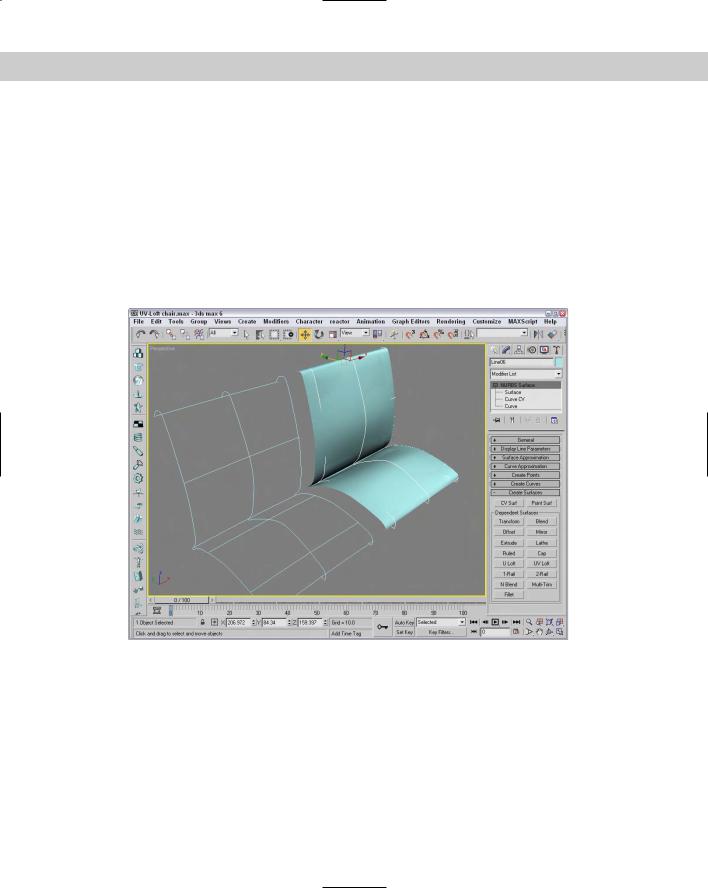
As an example, Figure 16-8 shows a chair seat that has been UV Lofted using three curves in the U direction and five curves in the V direction, thus enabling the surface to be contoured to fit a human being without our having to go back later and modify it by moving control vertices.
Figure 16-8: A UV Loft surface lofted from two sets of curves
This technique is very useful for building mechanical shapes, automobiles, and spaceships, and for modeling product designs.
Lathing a NURBS surface
Lathing a NURBS curve works the same way as lathing a spline. You simply need to select a curve, click the Lathe button in the Create Surface rollout (or click the Create Lathe Surface button in the NURBS Creation Toolbox), and then click the curve. You can change the Degrees value and the axis of rotation in the Lathe Surface rollout that appears under the Create Surfaces rollout in the Modify panel.
466 Part III Modeling
Tutorial: Lathing a NURBS CV curve to create a vase
In this tutorial, we create a NURBS CV curve profile shape. We then use this curve with the Lathe modifier to create a vase.
To create a Lathed NURBS surface, follow these steps:
1.Open the Lathed NURBS vase.max file from the Chap 16 directory on the CD-ROM. This file includes two CV curves that you can lathe to create a vase.
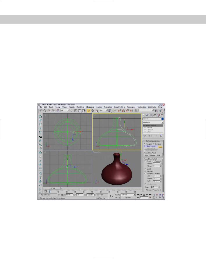
2.Select one of the CV curves, open the Modify panel, and click the Lathe button in the Create Surfaces rollout (or click the Create Lathe Surface button in the NURBS Creation Toolbox). In the Lathe Surface rollout that appears at the bottom of the Modify panel, enter a value of 360 in the Degrees field and click the Y-axis button. Then click on both CV curves to complete the lathe. Click the Lathe button again to exit Lathe mode.
Figure 16-9 shows the completed vase produced using the Lathe tool.
Figure 16-9: The lathed CV surface vase
Creating a 1-rail and 2-rail sweep surface
The 1-rail sweep surface tool lets you create a NURBS surface by using one NURBS curve to act as a side rail, and one or more profile shape curves to sweep along the rail to generate the surface. A 2-rail sweep surface is similar, except that it uses two NURBS curves as side rails.
Chapter 16 Working with NURBS 467
Tutorial: Creating a flower stem
Now that we have carefully constructed a flower vase, we need to create some flowers to place in the vase. We start with the flower stem.
To create a NURBS point surface using a 1-rail sweep, follow these steps:
1.Open the Flower stem.max file from the Chap 16 directory on the CD-ROM.
This file includes three cross sections and a curve correctly positioned that you can sweep to form a flower stem.
2.Select the long stem curve. Open the Modify panel, click the Attach button, and click the three cross-section shapes. Then click the Attach button again to exit attach mode.
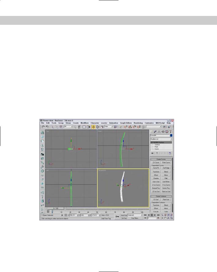
3.Open the Create Surfaces rollout, and click the 1-Rail (Sweep) button (or click the Create 1-Rail Sweep button in the NURBS Creation Toolbox). Click the long stem curve, and then click the cross-section shapes in order from the bottom to the top. Right-click to end the creation of the 1-rail sweep.
The NURBS skin is generated on the stem as shown in Figure 16-10.
Figure 16-10: A stem created with a 1-rail sweep

468 Part III Modeling
Sculpting a rectangular NURBS surface
NURBS patches are a quick way to create a surface that can be sculpted using the subobject elements, such as a control lattice. For each subobject type, you can use many different tools to form the patch.
Tutorial: Creating a NURBS leaf
In this tutorial, we create a NURBS CV surface plane that is sculpted into a leaf for the NURBS flower. To do this, we work in the Surface CV subobject level and use the Select and Move transform tool to move CVs and sculpt the NURBS rectangle into a leaf shape.
To create a rectangular NURBS CV surface, follow these steps:
1.Select Create NURBS CV Surface, and in the Create Parameters rollout, increase the Length CVs to 6 and Width CVs to 6. Click the Generate Mapping Coords check box.
2.In the Top viewport, click and drag to create the NURBS surface. In the Create Parameters rollout, set both the Length and Width to 180. While still in the Top viewport, rotate the NURBS surface 45 degrees along the Z-axis using the Select and Rotate tool so that it looks like a diamond shape.
3.With the NURBS surface selected, open the Modify panel and click the plus sign to the left of the NURBS Surface object to gain access to the subobjects. Select the Surface CV subobject.
The CV lattice is displayed in the Top viewport.
4.Select the Non-Uniform Scale tool (R), constrain it to the X-axis (F5), and then dragselect the middle horizontal row of CVs. Scale them down (narrower) to 85 percent.
5.Select the middle three horizontal rows of CVs (including the one just scaled), and scale them down to 90 percent. Then select the middle five horizontal rows, and scale them down to 90 percent.
This step gently rounds the outside contours of the NURBS surface.
6.In the Front viewport, you should see the edge of the NURBS surface. Maximize the viewport, and then select the Rotate tool, constrain it to the Z-axis, and select the right half of the CVs, but do not select the CVs at the very center. Rotate the CVs upward –60 degrees.
7.Repeat the select-and-rotate process with the CV on the left half of the center, but do not alter the CVs at the very center.
The leaf should now be U-shaped.
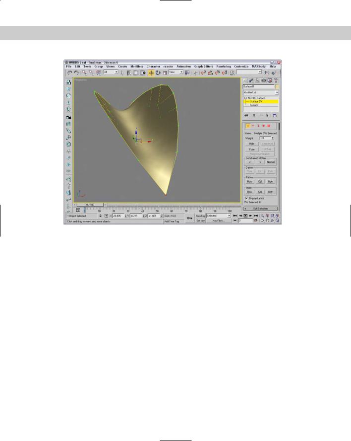
8.Click the Move tool (W), constrain it to the Y-axis (F6), and then select the center row of CVs and move them downward –40 units to make a deep V shape.
Figure 16-11 shows the NURBS leaf with the control lattice visible.
Chapter 16 Working with NURBS 469
Figure 16-11: Translating CVs to sculpt a NURBS leaf
Tutorial: Sculpting a flower petal
Continuing to build our flower, we now sculpt a second rectangular NURBS surface into the shape of a flower petal. In this case, the center CVs of the surface are raised to create a soft, rounded shape. We then sculpt one end of the NURBS rectangle into a blossom petal shape, and then scale and clone it to create three more petals.
To sculpt the flower petal shape, follow these steps:
1.Select Create NURBS CV Surface, and in the Keyboard Entry rollout, create a NURBS rectangular surface 80 units long and 80 units wide, with 6 Length CVs and 6 Width CVs.
2.Select the Rotate tool (or press the E key), and in the Top view, rotate the surface 45 degrees. Open the Modify panel, click the plus sign to the left of the NURBS Surface object, and select the Surface CV subobject.
3.Select the Non-Uniform Scale tool (R), constrain it to the X-axis (F5), and then select the center horizontal row of CVs and scale it down (narrower) to 86 percent.
This step rounds the outside corners of the petal.
4.Drag-select the six CVs that make up the upper tip of the petal. Non-uniform-scale the triangle of CVs in the Y-axis down to 35 percent to blunt the point at the top of the petal.
470 Part III Modeling
5.Click and drag a selection box around all the CVs in the center of the petal (don’t select any CVs on the edges). You can use the Ctrl key to add CVs to the selection and the Alt key to remove CVs from the selection. In the Front viewport, select the Move tool and move the CVs upward 6 units in the Y-axis to round the top of the petal.
6.In the Top viewport, select the lower half of the center vertical row of CVs, click the Lock Selection icon (or press the spacebar), and then in the Front viewport use the Move tool to move the CVs 7 units downward in the Y-axis. When a groove appears halfway down the center of the petal, unlock the selection set.
7.To clone the petal, turn off subobject mode and activate the Top viewport. Select World from the Reference Coordinate System drop-down list. Click the Mirror icon to open the Mirror: Screen Coordinates dialog box, and then clone the petal by selecting the Y-axis and Copy options. Move the new petal downward in the Y-axis so that the points of the petals touch.
8.Now clone the petals again, but make them smaller. Select the Uniform Scale button (or press the R key), select both petals in the Top viewport, and then press the Shift key and scale the petals down to 40 percent to create smaller cloned versions of the petals. Lock the selection set (press the spacebar), click Rotate (E), and then rotate the small petals 90 degrees to finish the blossom.
Figure 16-12 shows the completed flower.
Figure 16-12: Flower petals that were sculpted using NURBS
Chapter 16 Working with NURBS 471
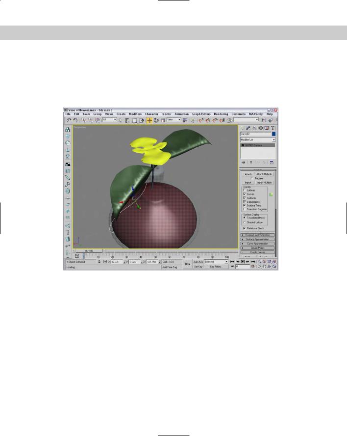
To finish the flower and vase model, you need to merge all the parts of the flower vase project into one scene. Clone and position the leaves next to the stem. Position the stem in the throat of the vase at a slight angle. Position the leaves midway up the stem, and then place the flower at the top of the stem, at right angles to the leaves. Finally, texture-map all objects, applying a glass material to the vase, dark green to the leaves and stem, and a pink and white radial gradient to each petal of the blossom. The finished flower is shown in Figure 16-13.
Figure 16-13: A vase and flower built completely from NURBS
NURBS modifiers
The Modifiers NURBS Editing menu includes a set of modifiers unique to NURBS objects. This set includes the following modifiers: NURBS Surface Select, Surf Deform, and Disp Approx. There is also a World-Space modifier called Displace NURBS.
The NURBS Surface Select modifier (known in the Modifier List at NSurfSel) lets you make a subobject selection for the selected NURBS object. This selection is then passed up the Modifier Stack to the next modifier. The two subobjects for this modifier are Surface CV and Surface.
The Surf Deform modifier works on NURBS surfaces just like the PatchDeform and PathDeform modifiers. After applying this modifier, you can select another NURBS object with the Pick Object button to deform the selected NURBS object. This modifier also has a World-Space version.