


Chapter 3 Working with Files and XRefs |
97 |
Each entry in the log file includes a date-time stamp and a three-letter designation of the type of message with DBG for debug, INF for info, WRN for warning, and ERR for error messages followed by the message. The name of the log file is Max.log. It is saved in the 3dsmax\ network subdirectory.
Importing and Exporting
If you haven’t noticed, Max isn’t the only game in town. A number of different 3D packages exist, and exchanging files between them is where the importing and exporting menu commands come in. You can find both of these commands in the File menu.
Importing supported formats
Choose File Import to open the Import dialog box. This dialog box looks like a typical Windows file dialog box. The real power comes with the various Import Settings dialog boxes that are available for each format. The settings in the Import Settings dialog box are different for the various format types.
Another common import dialog box offers options to merge the imported objects with the current scene or to completely replace the current scene. For many formats, you can also convert units on the imported file. For example, importing a 3D Studio file opens a simple dialog box, shown in Figure 3-7. With the Convert Units option selected, Max assumes that the 3DS file is based in inches and converts it to the currently defined units.
Figure 3-7: The 3DS Import dialog box enables you to merge objects into or completely replace the current scene.
If any of the object names in the imported scene match those in the current scene, an Import Name Conflict dialog box opens, allowing you to rename the imported objects, or you can Skip or Cancel the import.
New |
The ability to import VIZ Material XML files is new to 3ds max 6. |
Feature |
|
Max can import several different formats, including the following:
3D Studio Mesh, Projects, and Shapes (3DS, PRJ, SHP)
Adobe Illustrator (AI)
AutoCAD (DWG, DXF)
FiLMBOX (FBX)
98 |
Part I Learning the Max Interface |
Initial Graphics Exchange Standard (IGE, IGS, IGES)
Lightscape (LS, VW, LP)
StereoLithography (STL)
VRML (WRL, WRZ)
VIZ Material XML Import (XML)
In addition to importing, you’ll sometimes want to export Max objects for use in other programs. You access the Export command by choosing File Export. You also have the option to Export Selected (available only if an object is selected).
New |
The ability to export to the Shockwave 3D Scene (W3D) is new to 3ds max 6. |
Feature |
|
Max can export to several different formats, including the following:
3D Studio (3DS)
Adobe Illustrator (AI)
ASCII Scene Export (ASE)
Lightscape Material, Blocks, Parameters, Layers, Preparations, and Views (ATR, BLK, DF, LAY, LP, VW)
AutoCAD (DWG, DXF)
FiLMBOX (FBX)
Initial Graphics Exchange Standard (IGS)
StereoLithography (STL)
Shockwave 3D Scene Export (W3D)
VRML (WRL)
Import preference
The File panel of the Preference Settings dialog box has a single option dealing with importing — Zoom Extents on Import. When this option is enabled, it automatically zooms all viewports to the extent of the imported objects. Imported objects can often be scaled so small that they aren’t even visible. This option helps you to locate an object when imported.
Importing and exporting 3D Studio files (3DS, PRJ, SHP)
It shouldn’t be a surprise that Max can import 3D Studio (3DS) files without much headache — after all, 3D Studio was the predecessor to Max.
Everything in a 3DS file is imported into Max except for Morph Keys, Keyframer Instances,
.CUB cubic maps, and decal transparency defined by the upper-left pixel. Imported SHP files convert 2D polygons created with 3D Studio’s Shaper tool into Bézier splines. The shapes can be imported as a single object or as multiple objects. PRJ files are simply 3DS files that include shapes. Or, you can select to not import shapes.
Chapter 3 Working with Files and XRefs |
99 |
Note |
Max used to ask whether you want to set the animation length of the current scene to match |
|
the animation length in the 3DS file, but it now automatically creates a keyframe for every |
|
frame. You may want to use the Reduce Keys function in the Track View to simplify the ani- |
|
mation keys after importing. |
Max can export only to the 3DS format, not to the PRJ and SHP formats. After you select Export, the Export Scene to .3DS File dialog box appears with only one option — to Preserve Max’s Texture Coordinates. When you are exporting to the 3DS format, all mesh characteristics are exported except for any composite or procedural maps, UV mapping coordinates, any transformations applied to a group, and global shadow parameters.
Any objects that aren’t represented by meshes, such as NURBS and procedural primitives, are converted to meshes.
Importing and exporting Illustrator files (AI)
You can import files created using Adobe Illustrator into Max. After you have selected an Illustrator file, the AI Import dialog box offers the same options of merging the objects into the current scene or replacing the current scene. Next, the Shape Import dialog box appears with options to import the shapes as a single object or as multiple objects. During the import process, the 2D polygons are all converted to Bézier curves. Max can import only curves and paths from Illustrator. All effects such as fills, gradients, and filter effects are lost in the translation.
Note |
Max cannot import text created in Illustrator unless it has been converted to outlines. |
Only shapes and splines can be exported to the AI format. If you try to export a Max file that doesn’t include any shapes, you get a warning message, “No Data to export.” If you export a scene that includes shapes, the shapes are exported and all other objects are ignored. 3D splines can be exported, but their z-axis values are dropped.
Caution |
Helix shapes cannot be exported from Max unless they have converted to Editable Spline |
|
objects. |
Importing and exporting AutoCAD files (DWG, DXF)
AutoCAD is a sister product to Max, aimed at the computer-aided design market. It was produced by the same parent company, so it interacts very well with Max. AutoCAD uses two main formats: DWG (which stands for Drawing files) and the older DXF (which stands for Drawing Exchange Format).
Objects in AutoCAD are named differently from Max objects. For example, AutoCAD includes a 3D Face object, a Polyline Mesh object, a Polyface Mesh object, and an ACIS object. During the import process, all these objects are converted to corresponding mesh objects in Max, because Max doesn’t distinguish among these types.
New |
The AutoCAD DWG/DXF Import Options and export dialog boxes have been changed in |
Feature |
3ds max 6. |
|
100 Part I Learning the Max Interface
The AutoCAD DWG/DXF Import Options dialog box, shown in Figure 3-8, includes many options that help define the translation process. The dialog box is split into three panels — Geometry, Layers, and Spline Rendering. The Geometry panel includes options defining how to handle 3D objects and surfaces; the Layers panel lists all the various layers and their properties; and the Spline Rendering panel includes options defining how to handle imported splines.
Figure 3-8: The AutoCAD DWG/DXF import and export dialog boxes include many options.
Exporting to the DXF format opens the Export to AutoCAD File dialog box, which includes options to save the scene using the AutoCAD 2004 or AutoCAD 2000 formats.
Importing and exporting FilmBox files (FBX)
Another common 3D format was created by a company named Kaydara for its FilmBox product. FilmBox is used to work with motion capture data. Files saved in this format have the .fbx extension.
The Import FBX File dialog box, shown in Figure 3-9, lets you import any animation sequences listed in the top list box. These animation sequences can be merged, exclusive merged, or added to a new scene. You can also specify to import a Bones, Geometries, Cameras, Lights, Markers, Shapes, Animations, and Human IK. You also have the options to Rescale scene root nodes to unit size and rotate the root nodes with Y-up to Z-up.
Tip Both SoftImage and Maya support the FilmBox file format, so this format can be used to move scenes between these systems.
The export options include the same set of objects with the addition of Skin objects. You can also set the Resampling rate and enable options to Show Warnings and to embed textures. The Export FBX File dialog box is also shown in Figure 3-9.

Chapter 3 Working with Files and XRefs 101
Figure 3-9: The Import and Export FBX File dialog boxes allow you to import and export animation sequences.
Importing and exporting IGES files (IGES)
IGES stands for Initial Graphics Exchange Standard. The IGES format supports NURBS and provides a standard way to import and export NURBS objects. With IGES import and export features, Max files can share objects with packages such as Mechanical Desktop, Maya, Pro/ENGINEER, SoftImage, and CATIA, among others.
When you import an IGES file, the only dialog box to appear is the Merge/Replace dialog box shown in earlier sections.
In the IGES format, all entities have an entity number and name. The Max Online Reference includes a table that correlates the conversion of the various IGES entities to Max objects. For example, an IGES element labeled 100 is a Circular Arc that is converted to a Max Arc Shape.
IGES conversion can be tricky, so a log file of the process is saved with the .XLI extension. An IGES file with several meshes is converted to a single NURBS surface in Max with each original mesh being a separate subobject surface. To work with these subobject surfaces, you need to make them independent from the NURBS object.
Cross- |
Chapter 16, “Working with NURBS,” covers NURBS in more detail. |
Reference |
|
Exporting objects to the IGES format presents a single simple dialog box with options to Export Hidden Objects and to Export Selected Objects Only.
102 Part I Learning the Max Interface
Importing and exporting Lightscape files
Lightscape is an architectural rendering system that can generate scenes with an advanced lighting method known as radiosity. Radiosity simulates real lighting effects by taking into account how light bounces off objects.
Cross- |
Many of the features from the Lightscape product have been included in Max. You can find |
Reference |
information on these features in Chapter 29, “Advanced Lighting and Radiosity.” |
|
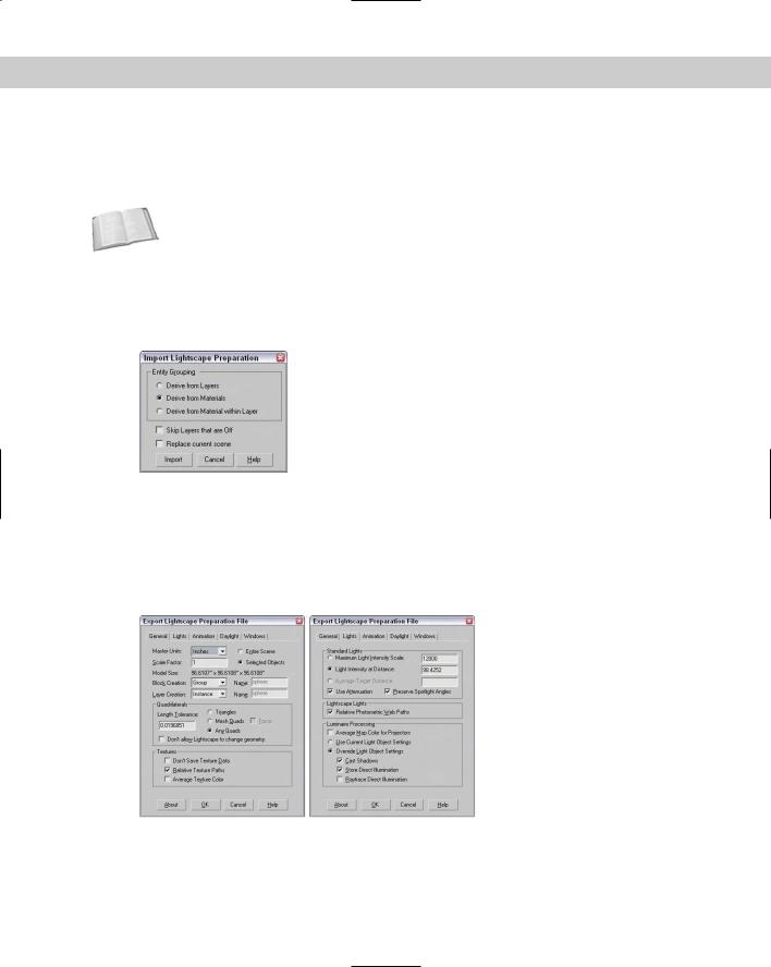
Files saved in Lightscape with the .LS, .VW, or .LP extensions can be imported into Max. These represent older Lightscape files, Lightscape Views, and Lightscape Preparation files. Importing a Lightscape Preparation file opens the dialog box shown in Figure 3-10. This dialog box lets you group entities by layers, materials, or materials within layers. You can also select to skip any layers that are off and replace the current scene.
Figure 3-10: The Import Lightscape Preparation dialog box can specify how entity grouping is derived.
Exporting Lightscape files offers many more options. Max files can be exported to Lightscape as Lightscape Materials (ATR), Blocks (BLK), Parameters (DF), Layers (LAY), Preparation (LP), and Views (VW). Each of these formats has its own unique export options.
The Lightscape format with the most options is the Preparation files. The other Lightscape formats have many of the same options. Figure 3-11 shows two panels (General and Lights) on the Export Lightscape Preparation File dialog box.
Figure 3-11: The Export Lightscape Preparation File dialog box includes multiple panels of options.
Chapter 3 Working with Files and XRefs 103
Importing and exporting StereoLithography files (STL)
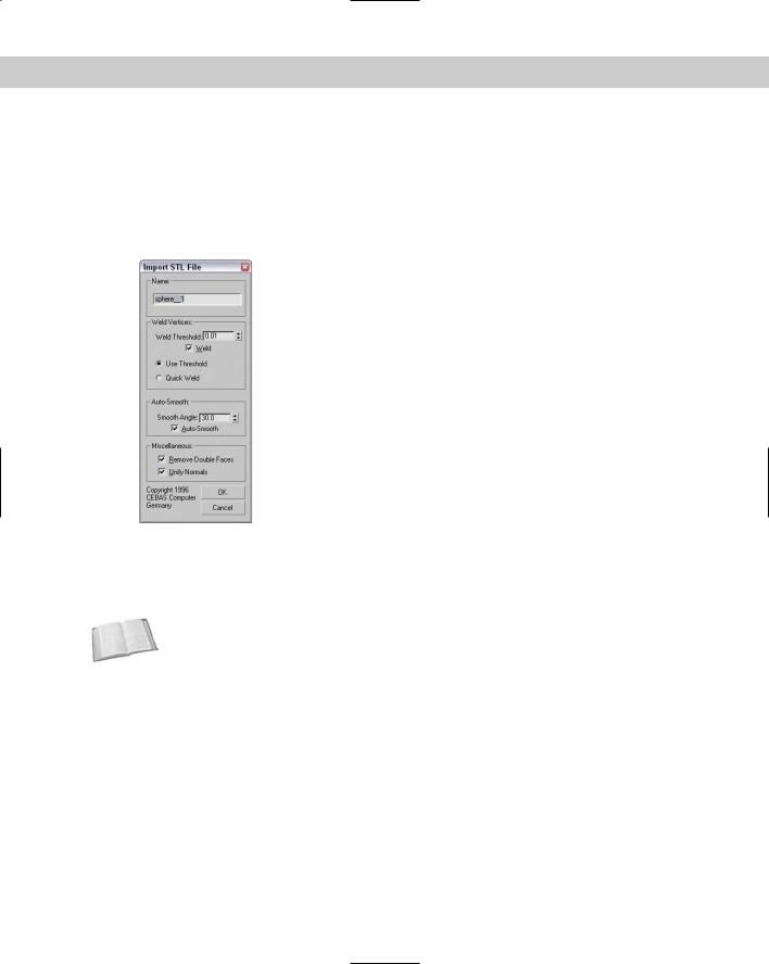
StereoLithography is a file format used by various manufacturing machines for rapid prototyping of products. Importing an STL file opens the Import STL File dialog box, shown in Figure 3-12. Available options include Weld Vertices (including a Quick Weld feature), which
you use to combine vertices closer than the Weld Threshold value; Auto-Smooth, which defines whether adjacent polygon faces should be smoothed; Unify Normals, which causes all normals to point the same direction; and Remove Double Faces, which simplifies the geometry.
Figure 3-12: The Import STL File dialog box enables you to name the STL file and set other options.
The Export STL File dialog box offers options for choosing whether to export the STL file as a Binary or ASCII file. Be aware that StereoLithography objects must be closed surfaces. Max includes the STL-Check modifier that verifies this. Using this modifier can save you some headaches when exporting.
Cross- |
You can learn about modifiers such as the STL-Check modifier in Chapter 11, “Introducing |
Reference |
Modifiers for Basic Object Deformation.” |
|
Importing and exporting VRML files (WRL, WRZ)
VRML stands for Virtual Reality Modeling Language and, like HTML, defines scenes that can be interpreted by VRML browsers embedded within a Web browser. Max can import VRML files with .WRL and .WRZ (which are compressed VRML files) file extensions, but can export only to the VRML97 standard with the .WRL extension.
Importing VRML files
The VRML Import dialog box includes options to Reset Scene, Turn to 3DS Coordinates, and Create Primitives. The Reset Scene option deletes the existing scene. Once deselected, the imported file merges into the current scene. The Turn to 3DS Coordinates option switches the Y and Z coordinates. In VRML scenes, the Y-axis points up, but in Max the Z-axis points up. The Create Primitives option converts VRML primitives to their Max equivalents.
104 Part I Learning the Max Interface
Exporting VRML97
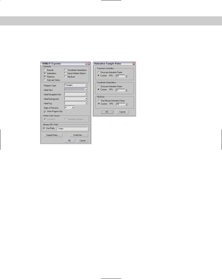
VRML97 is the only VRML format to which Max can export. The VRML97 Exporter dialog box, shown in Figure 3-13, includes many options, including generating Normals, Primitives, Color per Vertex, Coordinate Interpolators, and a Flip-Book.
Figure 3-13: The VRML97 Exporter dialog box includes options set by the VRML97 Helper. The Animation Sample Rates dialog box lets you define the frames per second.
The Initial View drop-down list lets you select a camera to display when the file first loads into a browser. Many VRML browsers support multiple viewpoints. Each camera in the scene becomes a different viewpoint when the VRML file is viewed in a browser. You can select Export Hidden Objects, but by default they are not exported. The Show Progress Bar displays a progress bar as the file is being exported, which is useful if you are trying to export a complex scene.
The Normals option aids the browser in rendering smooth objects. The Indentation option aligns the actual code to make it more readable in a text editor.
Primitives supported by the VRML browser are much more efficient than polygonal meshes. The Primitives option converts objects to primitive objects when possible.
The Color per Vertex option exports any vertex colors that are defined in the scene. You can also select Use Max’s Settings or Calculate on Export, which calculates vertex colors based on scene lighting. The Digits of Precision value can also be defined.
By default, all texture maps must reside in the same directory as the .WRL file. The Use Prefix option lets you define a subdirectory for holding any texture maps.
The Coordinate Interpolators option exports animation effects caused by Modifiers and Space Warps. The Flip-Book option exports VRML scenes as multiple files. Clicking the
Chapter 3 Working with Files and XRefs 105
Sample Rates button opens the Animation Sample Rates dialog box, also shown in Figure 3-13, which enables you to specify custom frame rates for the Flip-Book, for the Transform Controllers, and for the Coordinate Interpolators.
Note |
Exporting animation effects using the Coordinate Interpolators can produce huge VRML files. |
The Polygons Type section of the VRML97 Exporter dialog box lets you specify how individual faces are exported. Options include Ngons, Quads, Triangles, and Visible Edges. The Initial View drop-down list is still available, and below it are drop-down lists for Initial Navigation Info, Initial Background, and Initial Fog. All three are set by the VRML97 helper and are found as subcategories under the Helpers category in the Create panel.
The World Info button opens the World Info dialog box, in which you can give the VRML file a Title and file description.
The VRML97 Helper objects
To aid in the creation of VRML worlds, Max includes several additional helper objects. The VRML97 helper objects provide a way to add features such as anchors and sensors to scene objects in preparation for exporting a scene to the VRML97 format. You can find these tools as a subcategory under the Helpers category in the Create panel and also in the Create Helpers VRML97 menu.
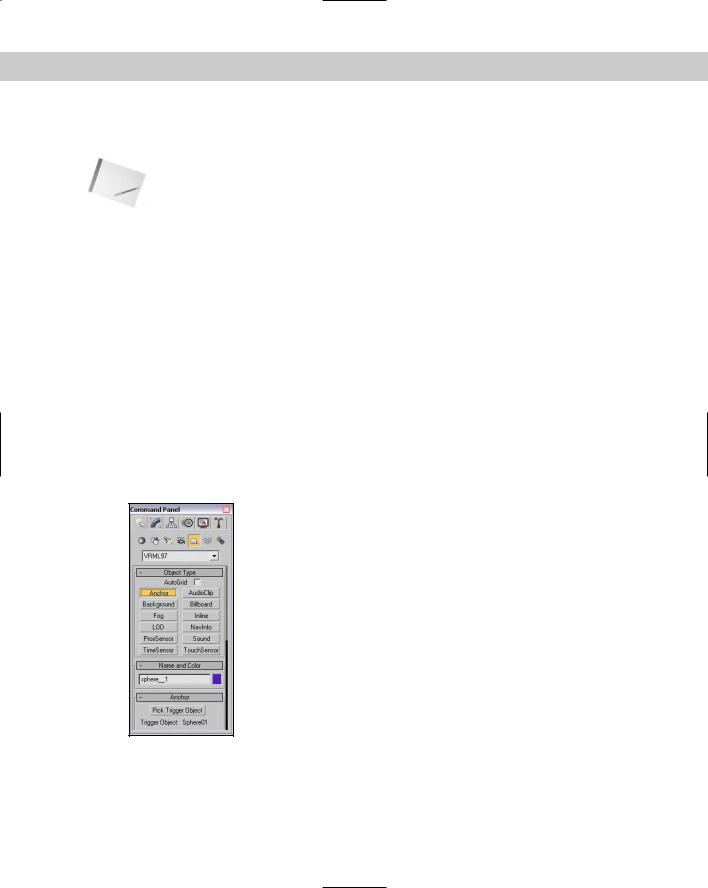
The VRML97 subcategory from the Helper category in the Create panel includes buttons for the following VRML97 features: Anchor, TouchSensor, ProxSensor, TimeSensor, NavInfo, Background, Fog, AudioClip, Sound, Billboard, LOD, and Inline, shown in Figure 3-14. Each of
these buttons opens a rollout containing its parameters. Many of these features are beyond the scope of this book but are covered in detail in the many VRML references that are available.
Figure 3-14: Use the VRML97 Helper objects to define export options for VRML files.
The Anchor rollout lets you pick a Trigger object that hyperlinks the user to a separate URL. The TouchSensor rollout lets you select objects to animate when a Trigger object is touched. The ProxSensor rollout lets you set a trigger when a user gets within a certain defined proximity to an object. The TimeSensor rollout sets regular time intervals.
106 Part I Learning the Max Interface
The NavInfo rollout tells the VRML Browser how the user can navigate about the VRML Scene. The Background rollout specifies the sky and ground colors and any images to use for the background. The Fog rollout lets you define how fog appears in the scene.
The AudioClip rollout is used in conjunction with the Sound rollout. The Sound rollout defines the sound characteristics, and the AudioClip rollout specifies where the sound clips are located. The Billboard rollout creates images that always face the user.
LOD stands for Level of Detail. This button opens a rollout containing a Pick Object button, a Distance value, and a list of objects. To add an object to the list, click the Pick Object button and then specify a Distance value for that object. When the VRML Browser gets closer than the specified distance, the object appears. You can use this procedure to display both a scaled-down version of an object when far away and a more detailed version up close.
The Inline button opens a rollout where you can add a Web URL link to the selected object. VRML browsers recognize this link when the object is clicked on.
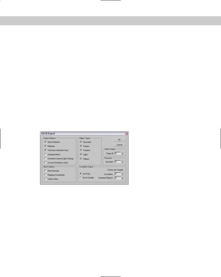
Exporting ASCII scene files (ASC, ASE)
To see all the gritty detail of a Max file, try exporting the file as an ASCII Scene file. The ASCII Export dialog box, shown in Figure 3-15, includes Output Options and Mesh Options. With this dialog box, you can also select which object types to export and specify an individual frame to export.
Figure 3-15: The ASCII Export dialog box exports the Max scene to a file that a text editor can read.
Exporting to the Shockwave 3D (W3D) format
Shockwave 3D is an interactive format used by Macromedia’s Director software. The exporter includes an Analysis tool and a Preview window. To export a Max scene to the Shockwave 3D format, select File Export or File Export Selected and select the Shockwave 3D format as the File Type in the file dialog box.
After giving the file a name and clicking OK, the Shockwave 3D Scene Export Options dialog box opens, as shown in Figure 3-16. This dialog box includes several options that you can include in the export file. You can also select a camera to use or choose to use the Active Viewport. The Compression Settings for Geometry, Texture, and Animation can be set to different quality settings between 0 and 100, and you can choose to limit the texture size.

Chapter 3 Working with Files and XRefs 107
Figure 3-16: The Shockwave 3D Scene Export Options dialog box lets you choose which resources to export.
The Shockwave 3D Export Options dialog box includes buttons that enable you to check the objects for any geometry abnormalities that will cause problems within a Shockwave viewer. After clicking the Author Check button, all geometries are checked, and another dialog box listing potential problems opens. Possible problems include the following:
Geometries with holes
Isolated vertices
Unsupported textures
Use of any Shaders other than Blinn
Unsupported modifier and controller animations
The Analyze button opens the Shockwave 3D File Analysis dialog box, shown in Figure 3-17. This dialog box shows a pie chart of the size of the various objects used in the scene.
The Preview button opens a Preview window, shown in Figure 3-18, where you can view the exported Shockwave 3D file. You can navigate about the Preview window by clicking and dragging with the left mouse button. Holding down the Shift key while dragging spins the viewpoint about its axis. Holding down the Ctrl key while dragging zooms in and out of the view, and dragging with the spacebar held down pans the view. Pressing the Shift key and the spacebar together constrains the panning motion to either horizontal or vertical.

108 Part I Learning the Max Interface
Figure 3-17: The Shockwave 3D File Analysis dialog box shows the size of your scene’s objects.
Figure 3-18: The Shockwave 3D Export Preview window lets you see what the exported Shockwave file will look like before exporting.
Exporting utilities
In addition to the menu commands found in the File menu, Max includes a couple of utilities that export specific information: the Lighting Data Export Utility and the Material XML Exporter Utility. You can access these utilities from the Utilities panel by clicking on the More button and selecting them from the pop-up list that appears.
Chapter 3 Working with Files and XRefs 109
New |
The Lighting Data Export and Material XML Exporter are new to 3ds max 6. |
Feature |
|
Lighting Data Export utility
The Lighting Data Export utility exports exposure control data for a scene’s Illuminance and Luminance values. These files can be saved as PIC or TIF files, which you can select in the 2D Lighting Data Exporter rollout. You also can set an image’s Width and Height dimensions.
Caution |
Exposure Control must be enabled for this utility to be enabled. You can learn about expo- |
|
sure control in Chapter 41, “Rendering Basics.” |
Material XML Exporter utility
The Material XML Exporter utility exports a selected material to an XML file format, where it can be easily shared with other users. After you select this utility, the Parameters rollout offers four options for selecting the material to export: the Material/Map Browser, the Object List, Pick Object in Scene, and All Objects in Scene.
The utility also offers several export options including Native XML, export to an Autodesk Tool Catalog, and using an XSLT template. You also can select to export the material with a thumbnail and along with its mapping modifiers.
Importing from external applications
Even if Max could import several times the current number of import formats, new formats are being created for new products all the time, many of which Max wouldn’t support. This situation does not mean that Max cannot use objects created in these new products. The trick is to find a common format that both products support.
Tutorial: Importing vector drawings from Illustrator
In most companies, a professional creative team uses an advanced vector drawing tool such as Illustrator to design the company logo. If you need to work with such a logo, learning how to import the externally created file gives you a jumpstart on your project.
Note |
When importing vector-based files into Max, only the lines are imported. Max cannot import |
|
fills, blends, or other specialized vector effects. All imported lines are automatically converted |
|
to Bézier splines in Max. |
Although Max can draw and work with splines, this feature takes a backseat to the vector functions available in Adobe Illustrator. If you have an Illustrator (AI) file, you can import it directly into Max.
To import Adobe Illustrator files into Max, follow these steps:
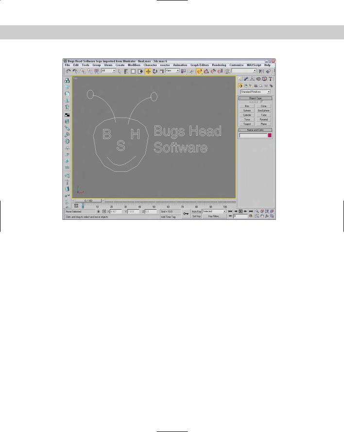
1.Within Illustrator, save your file as an AI file by choosing File Save As. Figure 3-19 shows a logo created using Illustrator.
110 Part I Learning the Max Interface
Figure 3-19: A company logo created in Illustrator and ready to save and import into Max
2.Open Max, and choose File Import. A file dialog box opens.
3.Select Adobe Illustrator (AI) as the File Type. Locate the file to import, and click OK.
The AI Import dialog box asks whether you want to merge the objects with the current scene or replace the current scene.
4.For our purposes, select the replace the current scene option and click OK.
5.The Shape Import dialog box asks whether you want to import the shapes as single or multiple objects. Select multiple, and click OK.
Figure 3-20 shows the logo after it has been imported into Max. Notice that all the fills are missing.
Cross- Spline objects that are imported from Illustrator appear in Max as Editable Spline objects. Reference You can learn more about Editable Splines in Chapter 13, “Drawing and Editing 2D Splines
and Shapes.”
Chapter 3 Working with Files and XRefs 111
Figure 3-20: A company logo created in Illustrator and imported into Max
Importing human figures from Poser
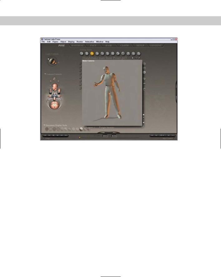
Many animation projects require human figures. Modeling a human figure from scratch can require the same patience and artistic skill that Michelangelo exercised when painting the ceiling of the Sistine Chapel. Luckily (for those of us facing deadlines), this level of commitment isn’t necessary. Curious Labs offers a tool devoted to modeling the human body. It is named Poser, and the current version is 5. Its features include posing and animating lifelike characters. Importing Poser models into Max can save you from some major modeling headaches.
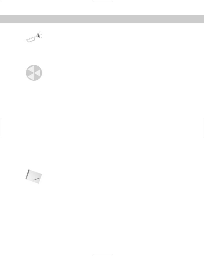
With Poser, you can choose from a variety of male and female human figures, both unclothed and clothed in all sorts of attire. Even animal models are available. You can easily position these figures to any pose. Figure 3-21 shows a model posed as if offering a handshake.
Poser can animate characters. To change the pose, simply click and drag a body part to its desired location. Poser also includes modules for controlling basic facial expressions and hand gestures.
112 Part I Learning the Max Interface
Figure 3-21: Poser by Curious Labs is an excellent tool for working with human figures.
Tutorial: Using Poser models in Max
Poser makes modeling and positioning human figures easy, but to get the figures into Max, you need to export them from Poser and import them into Max. Poser can export several formats, but only two coincide with Max: 3DS and DXF.
To use Poser models in Max, follow these steps:
1.Position your figure in Poser, and export it by choosing Poser’s File Export command.
2.In the Export dialog box, select the 3DS file type and save the file.
3.In Max, import the file by choosing File Import.
4.Select the Completely Replace Current Scene and Convert Units options, and click OK. The figure appears in the viewports.
5.Save the scene as a Max file by choosing File Save.
Figure 3-22 shows the imported figure.