

- •Preface
- •About This Book
- •Acknowledgments
- •Contents at a Glance
- •Contents
- •Relaxing at the Beach
- •Dressing the Scene
- •Animating Motion
- •Rendering the Final Animation
- •Summary
- •The Interface Elements
- •Using the Menus
- •Using the Toolbars
- •Using the Viewports
- •Using the Command Panel
- •Using the Lower Interface Bar Controls
- •Interacting with the Interface
- •Getting Help
- •Summary
- •Understanding 3D Space
- •Using the Viewport Navigation Controls
- •Configuring the Viewports
- •Working with Viewport Backgrounds
- •Summary
- •Working with Max Scene Files
- •Setting File Preferences
- •Importing and Exporting
- •Referencing External Objects
- •Using the File Utilities
- •Accessing File Information
- •Summary
- •Customizing Modify and Utility Panel Buttons
- •Working with Custom Interfaces
- •Configuring Paths
- •Selecting System Units
- •Setting Preferences
- •Summary
- •Creating Primitive Objects
- •Exploring the Primitive Object Types
- •Summary
- •Selecting Objects
- •Setting Object Properties
- •Hiding and Freezing Objects
- •Using Layers
- •Summary
- •Cloning Objects
- •Understanding Cloning Options
- •Mirroring Objects
- •Cloning over Time
- •Spacing Cloned Objects
- •Creating Arrays of Objects
- •Summary
- •Working with Groups
- •Building Assemblies
- •Building Links between Objects
- •Displaying Links and Hierarchies
- •Working with Linked Objects
- •Summary
- •Using the Schematic View Window
- •Working with Hierarchies
- •Setting Schematic View Preferences
- •Using List Views
- •Summary
- •Working with the Transformation Tools
- •Using Pivot Points
- •Using the Align Commands
- •Using Grids
- •Using Snap Options
- •Summary
- •Exploring the Modifier Stack
- •Exploring Modifier Types
- •Summary
- •Exploring the Modeling Types
- •Working with Subobjects
- •Modeling Helpers
- •Summary
- •Drawing in 2D
- •Editing Splines
- •Using Spline Modifiers
- •Summary
- •Creating Editable Mesh and Poly Objects
- •Editing Mesh Objects
- •Editing Poly Objects
- •Using Mesh Editing Modifiers
- •Summary
- •Introducing Patch Grids
- •Editing Patches
- •Using Modifiers on Patch Objects
- •Summary
- •Creating NURBS Curves and Surfaces
- •Editing NURBS
- •Working with NURBS
- •Summary
- •Morphing Objects
- •Creating Conform Objects
- •Creating a ShapeMerge Object
- •Creating a Terrain Object
- •Using the Mesher Object
- •Working with BlobMesh Objects
- •Creating a Scatter Object
- •Creating Connect Objects
- •Modeling with Boolean Objects
- •Creating a Loft Object
- •Summary
- •Understanding the Various Particle Systems
- •Creating a Particle System
- •Using the Spray and Snow Particle Systems
- •Using the Super Spray Particle System
- •Using the Blizzard Particle System
- •Using the PArray Particle System
- •Using the PCloud Particle System
- •Using Particle System Maps
- •Controlling Particles with Particle Flow
- •Summary
- •Understanding Material Properties
- •Working with the Material Editor
- •Using the Material/Map Browser
- •Using the Material/Map Navigator
- •Summary
- •Using the Standard Material
- •Using Shading Types
- •Accessing Other Parameters
- •Using External Tools
- •Summary
- •Using Compound Materials
- •Using Raytrace Materials
- •Using the Matte/Shadow Material
- •Using the DirectX 9 Shader
- •Applying Multiple Materials
- •Material Modifiers
- •Summary
- •Understanding Maps
- •Understanding Material Map Types
- •Using the Maps Rollout
- •Using the Map Path Utility
- •Using Map Instances
- •Summary
- •Mapping Modifiers
- •Using the Unwrap UVW modifier
- •Summary
- •Working with Cameras
- •Setting Camera Parameters
- •Summary
- •Using the Camera Tracker Utility
- •Summary
- •Using Multi-Pass Cameras
- •Creating Multi-Pass Camera Effects
- •Summary
- •Understanding the Basics of Lighting
- •Getting to Know the Light Types
- •Creating and Positioning Light Objects
- •Viewing a Scene from a Light
- •Altering Light Parameters
- •Working with Photometric Lights
- •Using the Sunlight and Daylight Systems
- •Using Volume Lights
- •Summary
- •Selecting Advanced Lighting
- •Using Local Advanced Lighting Settings
- •Tutorial: Excluding objects from light tracing
- •Summary
- •Understanding Radiosity
- •Using Local and Global Advanced Lighting Settings
- •Working with Advanced Lighting Materials
- •Using Lighting Analysis
- •Summary
- •Using the Time Controls
- •Working with Keys
- •Using the Track Bar
- •Viewing and Editing Key Values
- •Using the Motion Panel
- •Using Ghosting
- •Animating Objects
- •Working with Previews
- •Wiring Parameters
- •Animation Modifiers
- •Summary
- •Understanding Controller Types
- •Assigning Controllers
- •Setting Default Controllers
- •Examining the Various Controllers
- •Summary
- •Working with Expressions in Spinners
- •Understanding the Expression Controller Interface
- •Understanding Expression Elements
- •Using Expression Controllers
- •Summary
- •Learning the Track View Interface
- •Working with Keys
- •Editing Time
- •Editing Curves
- •Filtering Tracks
- •Working with Controllers
- •Synchronizing to a Sound Track
- •Summary
- •Understanding Your Character
- •Building Bodies
- •Summary
- •Building a Bones System
- •Using the Bone Tools
- •Using the Skin Modifier
- •Summary
- •Creating Characters
- •Working with Characters
- •Using Character Animation Techniques
- •Summary
- •Forward versus Inverse Kinematics
- •Creating an Inverse Kinematics System
- •Using the Various Inverse Kinematics Methods
- •Summary
- •Creating and Binding Space Warps
- •Understanding Space Warp Types
- •Combining Particle Systems with Space Warps
- •Summary
- •Understanding Dynamics
- •Using Dynamic Objects
- •Defining Dynamic Material Properties
- •Using Dynamic Space Warps
- •Using the Dynamics Utility
- •Using the Flex Modifier
- •Summary
- •Using reactor
- •Using reactor Collections
- •Creating reactor Objects
- •Calculating and Previewing a Simulation
- •Constraining Objects
- •reactor Troubleshooting
- •Summary
- •Understanding the Max Renderers
- •Previewing with ActiveShade
- •Render Parameters
- •Rendering Preferences
- •Creating VUE Files
- •Using the Rendered Frame Window
- •Using the RAM Player
- •Reviewing the Render Types
- •Using Command-Line Rendering
- •Creating Panoramic Images
- •Getting Printer Help
- •Creating an Environment
- •Summary
- •Creating Atmospheric Effects
- •Using the Fire Effect
- •Using the Fog Effect
- •Summary
- •Using Render Elements
- •Adding Render Effects
- •Creating Lens Effects
- •Using Other Render Effects
- •Summary
- •Using Raytrace Materials
- •Using a Raytrace Map
- •Enabling mental ray
- •Summary
- •Understanding Network Rendering
- •Network Requirements
- •Setting up a Network Rendering System
- •Starting the Network Rendering System
- •Configuring the Network Manager and Servers
- •Logging Errors
- •Using the Monitor
- •Setting up Batch Rendering
- •Summary
- •Compositing with Photoshop
- •Video Editing with Premiere
- •Video Compositing with After Effects
- •Introducing Combustion
- •Using Other Compositing Solutions
- •Summary
- •Completing Post-Production with the Video Post Interface
- •Working with Sequences
- •Adding and Editing Events
- •Working with Ranges
- •Working with Lens Effects Filters
- •Summary
- •What Is MAXScript?
- •MAXScript Tools
- •Setting MAXScript Preferences
- •Types of Scripts
- •Writing Your Own MAXScripts
- •Learning the Visual MAXScript Editor Interface
- •Laying Out a Rollout
- •Summary
- •Working with Plug-Ins
- •Locating Plug-Ins
- •Summary
- •Low-Res Modeling
- •Using Channels
- •Using Vertex Colors
- •Rendering to a Texture
- •Summary
- •Max and Architecture
- •Using AEC Objects
- •Using Architectural materials
- •Summary
- •Tutorial: Creating Icy Geometry with BlobMesh
- •Tutorial: Using Caustic Photons to Create a Disco Ball
- •Summary
- •mental ray Rendering System
- •Particle Flow
- •reactor 2.0
- •Schematic View
- •BlobMesh
- •Spline and Patch Features
- •Import and Export
- •Shell Modifier
- •Vertex Paint and Channel Info
- •Architectural Primitives and Materials
- •Minor Improvements
- •Choosing an Operating System
- •Hardware Requirements
- •Installing 3ds max 6
- •Authorizing the Software
- •Setting the Display Driver
- •Updating Max
- •Moving Max to Another Computer
- •Using Keyboard Shortcuts
- •Using the Hotkey Map
- •Main Interface Shortcuts
- •Dialog Box Shortcuts
- •Miscellaneous Shortcuts
- •System Requirements
- •Using the CDs with Windows
- •What’s on the CDs
- •Troubleshooting
- •Index
994 Part X Rendering
At the top of the frame buffer dialog box are several icon buttons. The first is the Save Bitmap button, which enables you to save the current frame buffer image.
The Clone Rendered Frame Window button creates another frame buffer dialog box. Any new rendering is rendered to this new dialog box, which is useful for comparing
two images.
The next four buttons enable the red, green, blue, and alpha channels. The alpha channel holds any transparency information for the image. The alpha channel is a grayscale map, with black showing the transparent areas and white showing the opaque areas. Next to the Display Alpha Channel button is the Monochrome button, which displays the image as a grayscale image.
 The Clear button erases the image from the window.
The Channel Display drop-down list lets you select the channel to display. The color swatch at the right shows the color of the currently selected pixel. You can select new pixels by rightclicking and holding on the image. This temporarily displays a small dialog box with the image dimensions and the RGB value of the pixel directly under the cursor. The color in the color swatch can then be dragged and dropped in other dialog boxes such as the Material Editor.
Using the RAM Player
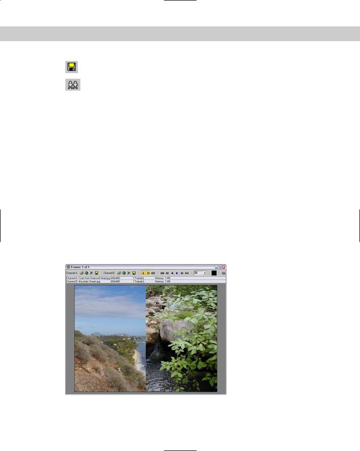
Just as you can use the Rendered Frame Window to view and compare rendered images, the RAM Player enables you to view rendered animations in memory. With animations loaded in memory, you can selectively change the frame rates. Figure 41-12 shows the RAM Player interface, which you open by choosing Rendering RAM Player.
Figure 41-12: The RAM Player interface lets you load two different images or animations for comparison.
Chapter 41 Rendering Basics 995
The buttons at the top of the RAM Player interface window, shown in Table 41-1, enable you to load an image to two different channels named A and B. The two Open Channel buttons open a file dialog box where you can select the file to load. Notice that the image on the right side of the RAM Player is a different frame than the left side.
|
Table 41-1: RAM Player Interface Buttons |
|
|
Button |
Description |
|
|
|
Open Channel |
|
Open Last Rendered Image |
|
Close Channel |
|
Save Channel |
|
Horizontal/Vertical Screen Split |
|
Double Buffer |
|
|
The Open Last Rendered Image button in the RAM Player interface window provides quick access to the last rendered image. The Close Channel button clears the channel. The Save Channel button opens a file dialog box for saving the current file.
Caution |
All files that load into the RAM Player are converted to 24-bit images. |
The Channel A and Channel B (toggle) buttons enable either channel or both. The Horizontal/ Vertical Screen Split button switches the dividing line between the two channels to a horizontal or vertical line. When the images are aligned one on top of the other, two small triangles mark where one channel leaves off and the other begins. You can drag these triangles to alter the space for each channel.
The frame controls let you move between the frames. You can move to the first, previous, next, or last frame and play the animation forward or in reverse. The drop-down list to the right of the frame controls displays the current frame rate setting.
You can capture the color of any pixel in the image by holding down the Ctrl key while clicking the image with the right mouse button. This puts the selected color in the color swatch. The RGB value for this pixel is displayed in the blue title bar.
The Double Buffer button synchronizes the frames of the two channels.
Tip |
You can use the arrow keys and Page Up and Page Down keys to move through the frames |
|
of the animation. The A and B keys are used to enable the two channels. |

996 Part X Rendering
Reviewing the Render Types
From the main toolbar, the Render Type drop-down list enables you to render subsections of the scene. The default setting is View. This renders the entire view as shown in the active viewport. After you pick a selection from the list, click the Quick Render button or the Render button in the Render Scene dialog box to begin the rendering.
The Selected setting renders only the selected objects in the active viewport. The Region setting puts a frame of dotted lines with handles in the active viewport. This frame lets you define a region to render. You can resize the frame by dragging the handles. When you have defined the region, click the OK button that appears in the lower-right corner of the active viewport.
The Crop setting is similar to Region in that it uses a frame to define a region, but the Crop setting doesn’t include the areas outside the defined frame. The Blowup setting takes the defined region and increases its size to fill the render window. The frame for Blowup is constrained to the aspect ratio of the final resolution.
The Box Selected setting renders the selected objects, but it presents a dialog box where you can specify the dimensions for rendering the bounding box of the selected objects. Constrain the Aspect Ratio is an additional option. The Region Selected option renders only the objects within the boundary box of the selected object. The rest of the scene is unchanged. The Crop Selected option also renders the objects within the boundary box of the selected object and crops the scene to this area.
Using Command-Line Rendering
Within the default installation directory is a file named 3dsmaxcmd.exe. This file lets you initiate the rendering of files using a command line interface. This feature enables you to create batch files that can be used to start Max, load several scenes, and render them automatically during the night while you sleep. You can find a command prompt interface in Windows XP using Start Program Files Accessories Command Prompt.
If you type 3dsmaxcmd -?, the command-line returns a list of available parameters that you can use. Typing 3dsmaxcmd –x returns several sample commands. The simplest command to render a scene called coolstuff.max would be 3dsmaxcmd coolstuff.max.
Using the various command line flags, you can specify an image size and format, use Render Preset files to control the renderer settings, and even submit a job for network rendering.
Creating Panoramic Images
The Panorama Exporter tool (found in the Rendering menu and in the Utilities panel) can be used to create a panoramic scene consisting of images rendering in all six directions from the current camera and stitched together.
New |
The Panorama Exporter tool is new to 3ds max 6. |
Feature |
|
Chapter 41 Rendering Basics 997
A camera needs to be added to the scene at the center of the panoramic view and the camera needs to be selected. You can quickly create a camera using the Perspective view with the Views Create Camera From View (Ctrl+C) command. Then click the Render button in the Panorama Exporter rollout. This opens a Render Scene dialog box where you can specify
the size of the images and the rest of the Render parameters. Click the Render button to render the panoramic scene.
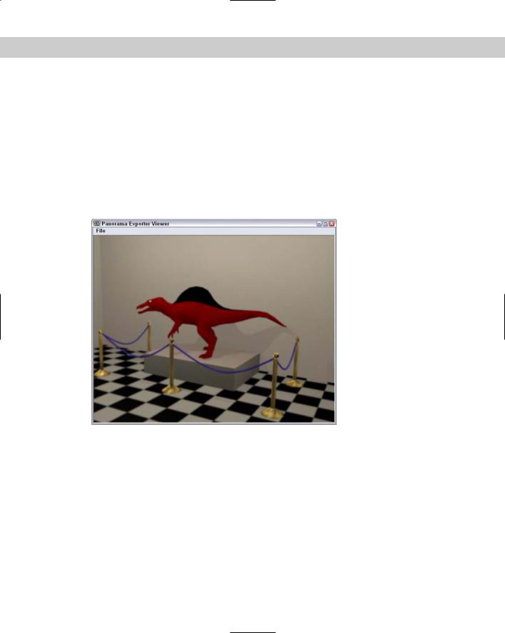
Once rendered, the panoramic scene will be opened within a Viewer, as shown in Figure 41-13, where you can move about the scene using the mouse. Dragging with the left mouse button spins the scene about its center point. Dragging with the middle mouse button zooms in and out of the scene. Dragging with the right mouse button pans the scene. The Viewer interface includes a File menu that can be used to open or export the scene file. Export options include a Cylinder, Sphere, and Quicktime VR.
Figure 41-13: The Panoramic Viewer lets you zoom, pan, and spin the scene about its center location.
Getting Printer Help
Printing still images from Max has always been a problem because you never knew quite knew what you would get. To solve this problem, Max now includes a Print Size Wizard that is located in the Rendering menu. This menu command opens the Print Size Wizard, as shown in Figure 41-14.