- •Preface
- •About This Book
- •Acknowledgments
- •Contents at a Glance
- •Contents
- •Relaxing at the Beach
- •Dressing the Scene
- •Animating Motion
- •Rendering the Final Animation
- •Summary
- •The Interface Elements
- •Using the Menus
- •Using the Toolbars
- •Using the Viewports
- •Using the Command Panel
- •Using the Lower Interface Bar Controls
- •Interacting with the Interface
- •Getting Help
- •Summary
- •Understanding 3D Space
- •Using the Viewport Navigation Controls
- •Configuring the Viewports
- •Working with Viewport Backgrounds
- •Summary
- •Working with Max Scene Files
- •Setting File Preferences
- •Importing and Exporting
- •Referencing External Objects
- •Using the File Utilities
- •Accessing File Information
- •Summary
- •Customizing Modify and Utility Panel Buttons
- •Working with Custom Interfaces
- •Configuring Paths
- •Selecting System Units
- •Setting Preferences
- •Summary
- •Creating Primitive Objects
- •Exploring the Primitive Object Types
- •Summary
- •Selecting Objects
- •Setting Object Properties
- •Hiding and Freezing Objects
- •Using Layers
- •Summary
- •Cloning Objects
- •Understanding Cloning Options
- •Mirroring Objects
- •Cloning over Time
- •Spacing Cloned Objects
- •Creating Arrays of Objects
- •Summary
- •Working with Groups
- •Building Assemblies
- •Building Links between Objects
- •Displaying Links and Hierarchies
- •Working with Linked Objects
- •Summary
- •Using the Schematic View Window
- •Working with Hierarchies
- •Setting Schematic View Preferences
- •Using List Views
- •Summary
- •Working with the Transformation Tools
- •Using Pivot Points
- •Using the Align Commands
- •Using Grids
- •Using Snap Options
- •Summary
- •Exploring the Modifier Stack
- •Exploring Modifier Types
- •Summary
- •Exploring the Modeling Types
- •Working with Subobjects
- •Modeling Helpers
- •Summary
- •Drawing in 2D
- •Editing Splines
- •Using Spline Modifiers
- •Summary
- •Creating Editable Mesh and Poly Objects
- •Editing Mesh Objects
- •Editing Poly Objects
- •Using Mesh Editing Modifiers
- •Summary
- •Introducing Patch Grids
- •Editing Patches
- •Using Modifiers on Patch Objects
- •Summary
- •Creating NURBS Curves and Surfaces
- •Editing NURBS
- •Working with NURBS
- •Summary
- •Morphing Objects
- •Creating Conform Objects
- •Creating a ShapeMerge Object
- •Creating a Terrain Object
- •Using the Mesher Object
- •Working with BlobMesh Objects
- •Creating a Scatter Object
- •Creating Connect Objects
- •Modeling with Boolean Objects
- •Creating a Loft Object
- •Summary
- •Understanding the Various Particle Systems
- •Creating a Particle System
- •Using the Spray and Snow Particle Systems
- •Using the Super Spray Particle System
- •Using the Blizzard Particle System
- •Using the PArray Particle System
- •Using the PCloud Particle System
- •Using Particle System Maps
- •Controlling Particles with Particle Flow
- •Summary
- •Understanding Material Properties
- •Working with the Material Editor
- •Using the Material/Map Browser
- •Using the Material/Map Navigator
- •Summary
- •Using the Standard Material
- •Using Shading Types
- •Accessing Other Parameters
- •Using External Tools
- •Summary
- •Using Compound Materials
- •Using Raytrace Materials
- •Using the Matte/Shadow Material
- •Using the DirectX 9 Shader
- •Applying Multiple Materials
- •Material Modifiers
- •Summary
- •Understanding Maps
- •Understanding Material Map Types
- •Using the Maps Rollout
- •Using the Map Path Utility
- •Using Map Instances
- •Summary
- •Mapping Modifiers
- •Using the Unwrap UVW modifier
- •Summary
- •Working with Cameras
- •Setting Camera Parameters
- •Summary
- •Using the Camera Tracker Utility
- •Summary
- •Using Multi-Pass Cameras
- •Creating Multi-Pass Camera Effects
- •Summary
- •Understanding the Basics of Lighting
- •Getting to Know the Light Types
- •Creating and Positioning Light Objects
- •Viewing a Scene from a Light
- •Altering Light Parameters
- •Working with Photometric Lights
- •Using the Sunlight and Daylight Systems
- •Using Volume Lights
- •Summary
- •Selecting Advanced Lighting
- •Using Local Advanced Lighting Settings
- •Tutorial: Excluding objects from light tracing
- •Summary
- •Understanding Radiosity
- •Using Local and Global Advanced Lighting Settings
- •Working with Advanced Lighting Materials
- •Using Lighting Analysis
- •Summary
- •Using the Time Controls
- •Working with Keys
- •Using the Track Bar
- •Viewing and Editing Key Values
- •Using the Motion Panel
- •Using Ghosting
- •Animating Objects
- •Working with Previews
- •Wiring Parameters
- •Animation Modifiers
- •Summary
- •Understanding Controller Types
- •Assigning Controllers
- •Setting Default Controllers
- •Examining the Various Controllers
- •Summary
- •Working with Expressions in Spinners
- •Understanding the Expression Controller Interface
- •Understanding Expression Elements
- •Using Expression Controllers
- •Summary
- •Learning the Track View Interface
- •Working with Keys
- •Editing Time
- •Editing Curves
- •Filtering Tracks
- •Working with Controllers
- •Synchronizing to a Sound Track
- •Summary
- •Understanding Your Character
- •Building Bodies
- •Summary
- •Building a Bones System
- •Using the Bone Tools
- •Using the Skin Modifier
- •Summary
- •Creating Characters
- •Working with Characters
- •Using Character Animation Techniques
- •Summary
- •Forward versus Inverse Kinematics
- •Creating an Inverse Kinematics System
- •Using the Various Inverse Kinematics Methods
- •Summary
- •Creating and Binding Space Warps
- •Understanding Space Warp Types
- •Combining Particle Systems with Space Warps
- •Summary
- •Understanding Dynamics
- •Using Dynamic Objects
- •Defining Dynamic Material Properties
- •Using Dynamic Space Warps
- •Using the Dynamics Utility
- •Using the Flex Modifier
- •Summary
- •Using reactor
- •Using reactor Collections
- •Creating reactor Objects
- •Calculating and Previewing a Simulation
- •Constraining Objects
- •reactor Troubleshooting
- •Summary
- •Understanding the Max Renderers
- •Previewing with ActiveShade
- •Render Parameters
- •Rendering Preferences
- •Creating VUE Files
- •Using the Rendered Frame Window
- •Using the RAM Player
- •Reviewing the Render Types
- •Using Command-Line Rendering
- •Creating Panoramic Images
- •Getting Printer Help
- •Creating an Environment
- •Summary
- •Creating Atmospheric Effects
- •Using the Fire Effect
- •Using the Fog Effect
- •Summary
- •Using Render Elements
- •Adding Render Effects
- •Creating Lens Effects
- •Using Other Render Effects
- •Summary
- •Using Raytrace Materials
- •Using a Raytrace Map
- •Enabling mental ray
- •Summary
- •Understanding Network Rendering
- •Network Requirements
- •Setting up a Network Rendering System
- •Starting the Network Rendering System
- •Configuring the Network Manager and Servers
- •Logging Errors
- •Using the Monitor
- •Setting up Batch Rendering
- •Summary
- •Compositing with Photoshop
- •Video Editing with Premiere
- •Video Compositing with After Effects
- •Introducing Combustion
- •Using Other Compositing Solutions
- •Summary
- •Completing Post-Production with the Video Post Interface
- •Working with Sequences
- •Adding and Editing Events
- •Working with Ranges
- •Working with Lens Effects Filters
- •Summary
- •What Is MAXScript?
- •MAXScript Tools
- •Setting MAXScript Preferences
- •Types of Scripts
- •Writing Your Own MAXScripts
- •Learning the Visual MAXScript Editor Interface
- •Laying Out a Rollout
- •Summary
- •Working with Plug-Ins
- •Locating Plug-Ins
- •Summary
- •Low-Res Modeling
- •Using Channels
- •Using Vertex Colors
- •Rendering to a Texture
- •Summary
- •Max and Architecture
- •Using AEC Objects
- •Using Architectural materials
- •Summary
- •Tutorial: Creating Icy Geometry with BlobMesh
- •Tutorial: Using Caustic Photons to Create a Disco Ball
- •Summary
- •mental ray Rendering System
- •Particle Flow
- •reactor 2.0
- •Schematic View
- •BlobMesh
- •Spline and Patch Features
- •Import and Export
- •Shell Modifier
- •Vertex Paint and Channel Info
- •Architectural Primitives and Materials
- •Minor Improvements
- •Choosing an Operating System
- •Hardware Requirements
- •Installing 3ds max 6
- •Authorizing the Software
- •Setting the Display Driver
- •Updating Max
- •Moving Max to Another Computer
- •Using Keyboard Shortcuts
- •Using the Hotkey Map
- •Main Interface Shortcuts
- •Dialog Box Shortcuts
- •Miscellaneous Shortcuts
- •System Requirements
- •Using the CDs with Windows
- •What’s on the CDs
- •Troubleshooting
- •Index
262 Part II Working with Objects
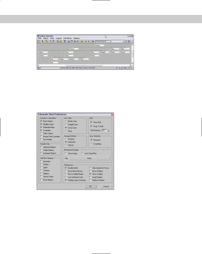
Figure 9-9: All character parts are now linked to the man’s pelvis part.
Setting Schematic View Preferences
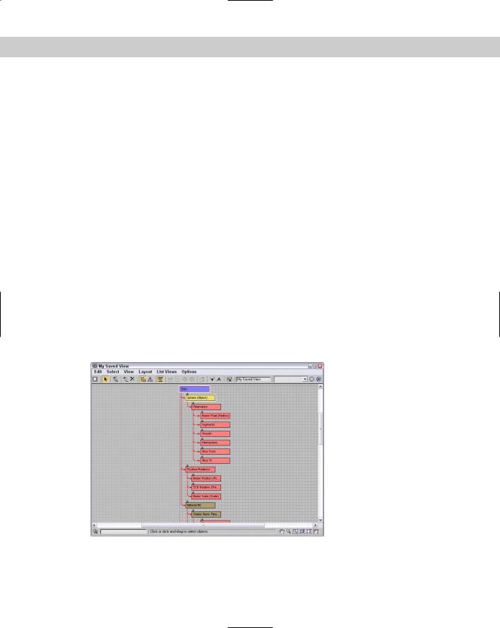
The Preferences button opens the Schematic View Preferences dialog box, shown in Figure 9-10, where you can set which items are displayed or hidden, set up grids and background images, and specify how the Schematic View window will look.
Figure 9-10: The Schematic View Preferences dialog box lets you customize many aspects of the Schematic View window.
Limiting nodes
When the Schematic View window is opened, Max transverses the entire hierarchy looking for objects and features that can be presented as nodes. If you have a complex scene and don’t intend on using the Schematic View to see materials or modifiers, you can disable them
Chapter 9 Working with the Schematic View 263
in the Include in Calculation section of the Schematic View Preferences dialog box. This provides a way to simplify the data that is presented. With less data, locating and manipulating what you are looking for becomes easier.
The Include in Calculation section includes options for limiting the following:
Base Objects: The geometry type that makes up a node. The node is the named object, such as Earth; the Base Object is its primitive, such as Sphere (Object).
Modifier Stack: Identifies all nodes with modifiers applied.
Materials/Maps: Identifies all nodes with materials and maps applied.
Controllers: Identifies all nodes that have controllers applied.
Static Values: Displays unanimated parameter values.
Master Point Controller: Displays nodes for any subobject selections that include controllers.
Skin Details: Displays nodes for the modifiers and controllers that are used when the Skin modifier is applied to a bones system.
You can also limit the number of nodes using the Include Only options. The Selected Objects option shows only the objects selected in the viewports. The nodes change as new objects are selected in the viewports. The Visible Objects option displays only the nodes for those objects that are not hidden in the viewports, and the Animated Objects option displays only the nodes of the objects that are animated.
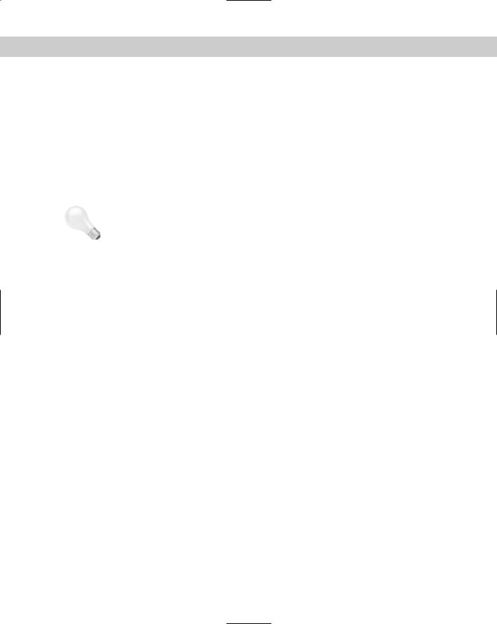
Object categories that can be hidden include Geometry, Shapes, Lights, Cameras, Helpers, Space Warps, and Bone Objects. Figure 9-11 shows a single sphere object in the Schematic View window with all the Include in Calculation options selected.
Figure 9-11: Without limiting nodes, the Schematic View window can get very busy.
264 Part II Working with Objects
|
Working with grids and backgrounds |
|
The Schematic View Preferences dialog box includes settings to Show Grid, Snap to Grid, and |
|
Grid Spacing. The keyboard shortcut for toggling the grid on and off is G. Enabling the Snap to |
|
Grid option makes the nodes snap to the closest grid intersection. This helps keep the nodes |
|
aligned and looking neat. |
|
The Background Image section of the Schematic View Preferences dialog box includes a File |
|
button that opens a file dialog box when clicked. Selecting an image file opens and displays |
|
the image as a background image. This is helpful as you arrange nodes. You need to select the |
|
Show Image option to see the background image, and the Lock Zoom/Pan option locks the |
|
nodes to the background image so zooming in on a set of nodes also zooms in on the back- |
|
ground image. |
Tip |
One of the easiest ways to get a background image of a model to use in the Schematic View |
|
is to render a single frame and save it from the Rendered Frame Window to a location where |
|
you can reopen it as the Schematic View background. |
Display preferences
In the Schematic View Preferences dialog box, you can select the style to use for relationship lines. The options include Bezier, Straight, Circuit, and None. When the Always Arrange, Arrange Children, or Arrange Selected options are used, you can select to have the nodes arranged Stacked, Horizontal, or Vertical. The Sync Selection options enable you to sync the selection between the Schematic View and the Viewports or between Everything. If the Everything option is selected, then not only are geometry objects in the viewports selected, but if a material is selected in the Schematic View, then the material is selected in the Material Editor also. Sync Selection Everything also affects the Modifier Stack, the Controller pane in the Display panel, and the Wiring Parameters dialog box.
The Schematic View Preferences dialog box also includes a Preferences section. These preference settings include Double Buffer, which enables a double-buffer display and helps improve the viewport update performance. The Zoom About Mouse Pointer preference enables zooming by using the scroll wheel on your mouse or by pressing the middle mouse button while holding down the Ctrl key. The Pan to Added Nodes preference automatically resizes and moves the nodes to enable you to view any additional nodes that have been added.
The Use Wireframe Color option changes the node colors to be the same as the viewport object color. The Display Layout Warning lets you disable the warning that appears every time you use the Always Arrange feature. The Only Update on Focus option causes the Schematic View to update only when the window is selected. Until then, any changes are not propagated to the window. This can be a timesaver when complex scenes require redraws.
The Show Tooltips option allows you to disable tooltips if you desire. Tooltips show in the Schematic View window when you hover the cursor over the top of a node. Tooltips can be
Chapter 9 Working with the Schematic View 265
handy if you’ve zoomed out so far that you can’t read the node labels; just move the cursor over a node, and its label appears. The Snap Floater option enables the Display and List floaters to be snapped to the edge of the window for easy access, and the Relative Floaters option moves and resizes the floaters along with the Schematic View window.
Tutorial: Adding a background image to the Schematic View
You can position nodes anywhere within the Schematic View window. For example, you can position the nodes to look something like the shape of the model that you’re linking. When positioning the different objects, having a background image is really handy.
To add a background image for the Schematic View, follow these steps:
1.Open the Futuristic man with background.max file in the Chap 09 directory on the CD-ROM.
This file uses the same futuristic man model used in the preceding example.
2.With the Perspective viewport maximized, select Tools Grab Viewport. Give the viewport the name of futuristic man — front view, and click the Grab button.
The viewport image opens the Rendered Frame Window.
3.Click the Save Bitmap button in the upper-left corner. Save the image as Futuristic man — front view.
4.Select Graph Editors New Schematic View to open a Schematic View window and name the view Background. Click the Preferences button on the Schematic View toolbar, and click the File button in the Background Image section.
5.Locate the saved image, and open it. Select the Show Image option in the Schematic View Preferences dialog box.
You can perform this step using the image file saved in the Chap 09 directory on the CD-ROM, if you so choose.
6.Select the View Show Grid menu command (or press the G key) to turn off the grid. Drag on the corner of the Schematic View interface to increase the size of the window so that the whole background image is visible.
7.Select each of the nodes, and drag them so that they are roughly positioned on top of the part that they represent. Start by moving the parent objects first, and then work to their children.
Figure 9-12 shows all the nodes aligned over their respective parts. From this arrangement, you can clearly see how the links are organized.