

- •Preface
- •About This Book
- •Acknowledgments
- •Contents at a Glance
- •Contents
- •Relaxing at the Beach
- •Dressing the Scene
- •Animating Motion
- •Rendering the Final Animation
- •Summary
- •The Interface Elements
- •Using the Menus
- •Using the Toolbars
- •Using the Viewports
- •Using the Command Panel
- •Using the Lower Interface Bar Controls
- •Interacting with the Interface
- •Getting Help
- •Summary
- •Understanding 3D Space
- •Using the Viewport Navigation Controls
- •Configuring the Viewports
- •Working with Viewport Backgrounds
- •Summary
- •Working with Max Scene Files
- •Setting File Preferences
- •Importing and Exporting
- •Referencing External Objects
- •Using the File Utilities
- •Accessing File Information
- •Summary
- •Customizing Modify and Utility Panel Buttons
- •Working with Custom Interfaces
- •Configuring Paths
- •Selecting System Units
- •Setting Preferences
- •Summary
- •Creating Primitive Objects
- •Exploring the Primitive Object Types
- •Summary
- •Selecting Objects
- •Setting Object Properties
- •Hiding and Freezing Objects
- •Using Layers
- •Summary
- •Cloning Objects
- •Understanding Cloning Options
- •Mirroring Objects
- •Cloning over Time
- •Spacing Cloned Objects
- •Creating Arrays of Objects
- •Summary
- •Working with Groups
- •Building Assemblies
- •Building Links between Objects
- •Displaying Links and Hierarchies
- •Working with Linked Objects
- •Summary
- •Using the Schematic View Window
- •Working with Hierarchies
- •Setting Schematic View Preferences
- •Using List Views
- •Summary
- •Working with the Transformation Tools
- •Using Pivot Points
- •Using the Align Commands
- •Using Grids
- •Using Snap Options
- •Summary
- •Exploring the Modifier Stack
- •Exploring Modifier Types
- •Summary
- •Exploring the Modeling Types
- •Working with Subobjects
- •Modeling Helpers
- •Summary
- •Drawing in 2D
- •Editing Splines
- •Using Spline Modifiers
- •Summary
- •Creating Editable Mesh and Poly Objects
- •Editing Mesh Objects
- •Editing Poly Objects
- •Using Mesh Editing Modifiers
- •Summary
- •Introducing Patch Grids
- •Editing Patches
- •Using Modifiers on Patch Objects
- •Summary
- •Creating NURBS Curves and Surfaces
- •Editing NURBS
- •Working with NURBS
- •Summary
- •Morphing Objects
- •Creating Conform Objects
- •Creating a ShapeMerge Object
- •Creating a Terrain Object
- •Using the Mesher Object
- •Working with BlobMesh Objects
- •Creating a Scatter Object
- •Creating Connect Objects
- •Modeling with Boolean Objects
- •Creating a Loft Object
- •Summary
- •Understanding the Various Particle Systems
- •Creating a Particle System
- •Using the Spray and Snow Particle Systems
- •Using the Super Spray Particle System
- •Using the Blizzard Particle System
- •Using the PArray Particle System
- •Using the PCloud Particle System
- •Using Particle System Maps
- •Controlling Particles with Particle Flow
- •Summary
- •Understanding Material Properties
- •Working with the Material Editor
- •Using the Material/Map Browser
- •Using the Material/Map Navigator
- •Summary
- •Using the Standard Material
- •Using Shading Types
- •Accessing Other Parameters
- •Using External Tools
- •Summary
- •Using Compound Materials
- •Using Raytrace Materials
- •Using the Matte/Shadow Material
- •Using the DirectX 9 Shader
- •Applying Multiple Materials
- •Material Modifiers
- •Summary
- •Understanding Maps
- •Understanding Material Map Types
- •Using the Maps Rollout
- •Using the Map Path Utility
- •Using Map Instances
- •Summary
- •Mapping Modifiers
- •Using the Unwrap UVW modifier
- •Summary
- •Working with Cameras
- •Setting Camera Parameters
- •Summary
- •Using the Camera Tracker Utility
- •Summary
- •Using Multi-Pass Cameras
- •Creating Multi-Pass Camera Effects
- •Summary
- •Understanding the Basics of Lighting
- •Getting to Know the Light Types
- •Creating and Positioning Light Objects
- •Viewing a Scene from a Light
- •Altering Light Parameters
- •Working with Photometric Lights
- •Using the Sunlight and Daylight Systems
- •Using Volume Lights
- •Summary
- •Selecting Advanced Lighting
- •Using Local Advanced Lighting Settings
- •Tutorial: Excluding objects from light tracing
- •Summary
- •Understanding Radiosity
- •Using Local and Global Advanced Lighting Settings
- •Working with Advanced Lighting Materials
- •Using Lighting Analysis
- •Summary
- •Using the Time Controls
- •Working with Keys
- •Using the Track Bar
- •Viewing and Editing Key Values
- •Using the Motion Panel
- •Using Ghosting
- •Animating Objects
- •Working with Previews
- •Wiring Parameters
- •Animation Modifiers
- •Summary
- •Understanding Controller Types
- •Assigning Controllers
- •Setting Default Controllers
- •Examining the Various Controllers
- •Summary
- •Working with Expressions in Spinners
- •Understanding the Expression Controller Interface
- •Understanding Expression Elements
- •Using Expression Controllers
- •Summary
- •Learning the Track View Interface
- •Working with Keys
- •Editing Time
- •Editing Curves
- •Filtering Tracks
- •Working with Controllers
- •Synchronizing to a Sound Track
- •Summary
- •Understanding Your Character
- •Building Bodies
- •Summary
- •Building a Bones System
- •Using the Bone Tools
- •Using the Skin Modifier
- •Summary
- •Creating Characters
- •Working with Characters
- •Using Character Animation Techniques
- •Summary
- •Forward versus Inverse Kinematics
- •Creating an Inverse Kinematics System
- •Using the Various Inverse Kinematics Methods
- •Summary
- •Creating and Binding Space Warps
- •Understanding Space Warp Types
- •Combining Particle Systems with Space Warps
- •Summary
- •Understanding Dynamics
- •Using Dynamic Objects
- •Defining Dynamic Material Properties
- •Using Dynamic Space Warps
- •Using the Dynamics Utility
- •Using the Flex Modifier
- •Summary
- •Using reactor
- •Using reactor Collections
- •Creating reactor Objects
- •Calculating and Previewing a Simulation
- •Constraining Objects
- •reactor Troubleshooting
- •Summary
- •Understanding the Max Renderers
- •Previewing with ActiveShade
- •Render Parameters
- •Rendering Preferences
- •Creating VUE Files
- •Using the Rendered Frame Window
- •Using the RAM Player
- •Reviewing the Render Types
- •Using Command-Line Rendering
- •Creating Panoramic Images
- •Getting Printer Help
- •Creating an Environment
- •Summary
- •Creating Atmospheric Effects
- •Using the Fire Effect
- •Using the Fog Effect
- •Summary
- •Using Render Elements
- •Adding Render Effects
- •Creating Lens Effects
- •Using Other Render Effects
- •Summary
- •Using Raytrace Materials
- •Using a Raytrace Map
- •Enabling mental ray
- •Summary
- •Understanding Network Rendering
- •Network Requirements
- •Setting up a Network Rendering System
- •Starting the Network Rendering System
- •Configuring the Network Manager and Servers
- •Logging Errors
- •Using the Monitor
- •Setting up Batch Rendering
- •Summary
- •Compositing with Photoshop
- •Video Editing with Premiere
- •Video Compositing with After Effects
- •Introducing Combustion
- •Using Other Compositing Solutions
- •Summary
- •Completing Post-Production with the Video Post Interface
- •Working with Sequences
- •Adding and Editing Events
- •Working with Ranges
- •Working with Lens Effects Filters
- •Summary
- •What Is MAXScript?
- •MAXScript Tools
- •Setting MAXScript Preferences
- •Types of Scripts
- •Writing Your Own MAXScripts
- •Learning the Visual MAXScript Editor Interface
- •Laying Out a Rollout
- •Summary
- •Working with Plug-Ins
- •Locating Plug-Ins
- •Summary
- •Low-Res Modeling
- •Using Channels
- •Using Vertex Colors
- •Rendering to a Texture
- •Summary
- •Max and Architecture
- •Using AEC Objects
- •Using Architectural materials
- •Summary
- •Tutorial: Creating Icy Geometry with BlobMesh
- •Tutorial: Using Caustic Photons to Create a Disco Ball
- •Summary
- •mental ray Rendering System
- •Particle Flow
- •reactor 2.0
- •Schematic View
- •BlobMesh
- •Spline and Patch Features
- •Import and Export
- •Shell Modifier
- •Vertex Paint and Channel Info
- •Architectural Primitives and Materials
- •Minor Improvements
- •Choosing an Operating System
- •Hardware Requirements
- •Installing 3ds max 6
- •Authorizing the Software
- •Setting the Display Driver
- •Updating Max
- •Moving Max to Another Computer
- •Using Keyboard Shortcuts
- •Using the Hotkey Map
- •Main Interface Shortcuts
- •Dialog Box Shortcuts
- •Miscellaneous Shortcuts
- •System Requirements
- •Using the CDs with Windows
- •What’s on the CDs
- •Troubleshooting
- •Index

Chapter 12 Modeling Basics 339
Figure 12-1: These flowers were created using an Editable Poly, an Editable Patch, a NURBS Surface, and an Editable Spline.
Working with Subobjects
All the editable modeling types offer the ability to work with subobjects. Subobjects are the elements that make up the model and can include vertices, edges, faces, polygons, and elements. These individual subobjects can be selected and transformed just like normal objects using the transformation tools located on the main toolbar. But, before you can transform these subobjects, you need to select them. You can select subobjects only when you’re in a particular subobject mode. Each editable object type has a different set of subobjects.
If you expand the object’s hierarchy in the Modifier Stack (by clicking the small plus sign to the left of the object’s name), all subobjects for an object are displayed, as shown in Figure 12-2. Selecting a subobject in the Modifier Stack places you in subobject mode for that subobject type. You can also enter subobject mode by clicking on the subobject icons located at the top of the Selection rollout or by pressing the 1 through 5 keys on the keyboard. When you’re in subobject mode, the subobject title and the icon in the Selection rollout are highlighted yellow. You can only work with the selected subobjects while in subobject mode. To transform the entire object again, you need to exit subobject mode, which you can do by clicking either the subobject title or the subobject icon, or by pressing one of the keyboard shortcuts, 1–5.
340 Part III Modeling
Tip |
You can also access the subobjects modes using the right-click Quadmenu. To exit a subob- |
|
ject mode, select Top Level in the Quadmenu. |
Subobjects
Figure 12-2: Expanding an editable object in the Modifier
Stack reveals its subobjects.
Subobjects icons
Subobject selections can be locked with the Selection Lock Toggle (spacebar) and be made into a Selection Set by typing a name into the Named Selection Set drop-down list on the main toolbar. After a Selection Set is created, you can recall it anytime you are in that same subobject mode. Named Selection Sets can then be copied and pasted between objects using
the Copy and Paste buttons found in the Selection rollout for most editable objects.
Using Soft Selection
When working with editable mesh, poly, patches, or splines, the Soft Selection rollout, shown in Figure 12-3, becomes available in subobject mode. Soft Selection selects all the subobjects surrounding the current selection and applies transformations to them to a lesser extent. For example, if a face is selected and moved a distance of 2, then with linear Soft Selection, the neighboring faces within the soft selection range move a distance of 1. The overall effect is a smoother transition.
Note |
The Soft Selection rollout also appears in several other places besides just editable objects. |
Chapter 12 Modeling Basics 341
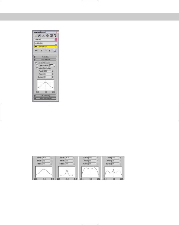
Figure 12-3: The Soft Selection rollout is available only in subobject mode.
Soft Selection curve
The Use Soft Selection parameter enables or disables the Soft Selection feature. The Edge Distance option sets the range (the number of edges from the current selection) that the Soft Selection will affect. If disabled, the distance is determined by the Falloff amount. The Affect Backfacing option applies the Soft Selection to selected subobjects on the backside of an object. For example, if you are selecting vertices on the front of a sphere object and the Affect Backfacing option is enabled, then vertices on the opposite side of the sphere are also selected.
The Soft Selection curve shows a graphical representation of how the Soft Selection is applied. The Falloff value defines the spherical region where the Soft Selection has an effect. The Pinch button sharpens the point at the top of the curve. The Bubble button has an opposite effect and widens the curve. Figure 12-4 shows several sample values and the resulting curve.
Figure 12-4: The Soft Selection curve is affected by the Falloff, Pinch, and Bubble values.
342 Part III Modeling
Tutorial: Soft selecting a heart shape from a plane
Soft Selection enables a smooth transition between subobjects, but sometimes you want the abrupt edge. This tutorial looks at moving some subobject vertices in a plane object with and without Soft Selection enabled.
To move subobject vertices with and without Soft Selection, follow these steps:
1.Open the Soft selection heart.max file from the Chap 12 directory on the CD-ROM.
This file contains two simple plane objects that have been converted to Editable Mesh objects. Several vertices in the shape of a heart are selected.
2.The vertices on the first plane object are already selected; in Vertex subobject mode, click the Select and Move button (or press the W key), move the cursor over the selected vertices, and drag upward in the Left viewport away from the plane.
3.Exit subobject mode, select the second plane object, and enter Vertex subobject mode. The same vertices are again selected. Open the Soft Selection rollout, enable the Use Soft Selection option, and set the Falloff value to 40.
4.Click the Select and Move button (or press the W key), and move the selected vertices upward. Notice the difference that Soft Selection makes.
Figure 12-5 shows the two resulting plane objects with the heart selections.
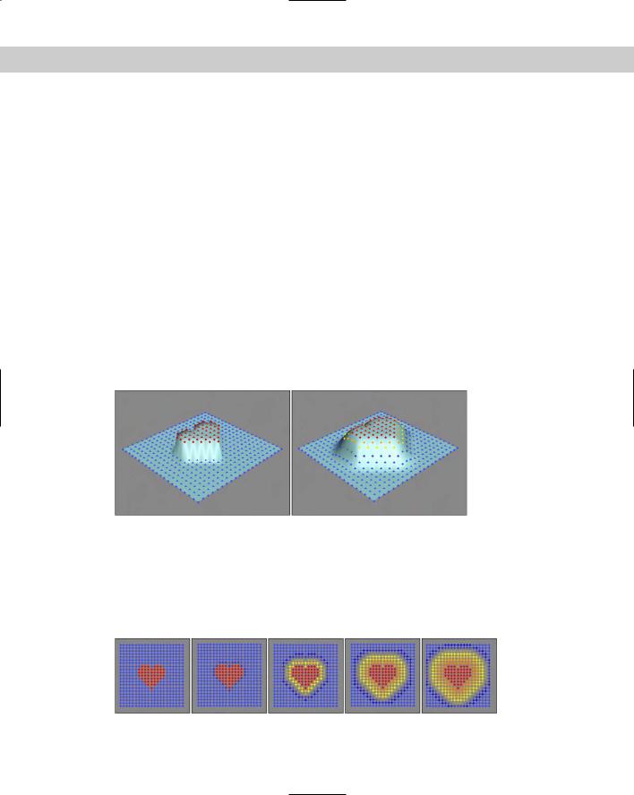
Figure 12-5: Soft Selection makes a smooth transition between the subobjects that are moved and those that are not.
When you select subobjects, they turn red. Non-selected subobjects are blue, and soft selected subobjects are colored a gradient from orange to yellow depending on their distance from the selected subobjects. This visual clue provides valuable feedback on how the Soft Selection affects the subobjects. Figure 12-6 shows the selected vertices from the preceding tutorial with Falloff values of 0, 20, 40, 60, and 80.
Figure 12-6: A gradient of colors shows the transition zone for soft selected subobjects.
Chapter 12 Modeling Basics 343
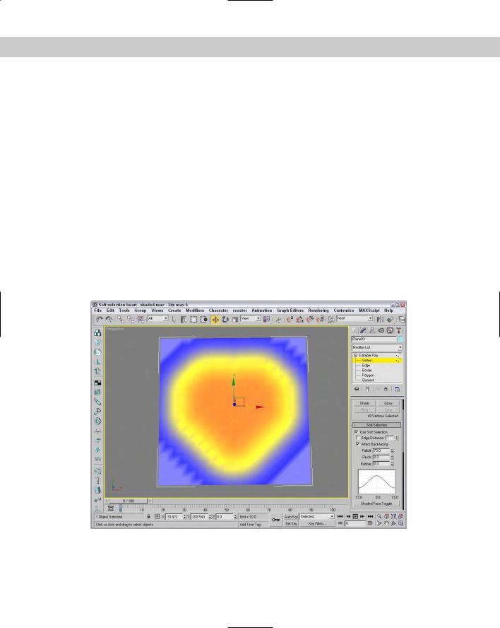
For the Editable Poly and Editable Patch objects, the Soft Selection rollout includes a Shaded Face Toggle button below its curve. This button shades the surface using the soft selection gradient colors, as shown in Figure 12-7. This shaded surface is displayed in any shaded viewports.
Applying modifiers to subobject selections
The preceding chapter introduced modifiers and showed how they can be applied to entire objects. But, you can also apply modifiers to subobjects. If the modifier isn’t available for subobjects, it is excluded from the Modifier List or disabled in the Modifiers menu.
If your object isn’t an editable object with available subobjects, you can still apply a modifier using one of the specialized Select modifiers. These modifiers let you select a subobject and apply a modifier to it without having to convert it to a non-parametric object. These Select modifiers include Mesh Select, Poly Select, Patch Select, Spline Select, Volume Select, FFD Select, and NURBS Surface Select. You can find all these modifiers in the Modifiers Selection Modifiers submenu.
After you apply a Select modifier to an object, you can select subobjects in the normal manner using the hierarchy in the Modifier Stack or the subobject icons in the Parameters rollout. Any modifiers that you apply after the Select modifier (they appear above the Select modifier in the Modifier Stack) affect only the subobject selection.
Figure 12-7: The Shaded Face Toggle shades the surface using the soft selection gradient colors.
344 Part III Modeling
Tutorial: Building a Superman logo
Applying modifiers to a subobject selection is accomplished by passing the subobject selection up the Stack. This means that the Select modifier needs to come below the other modifier in the Modifier Stack. To give you some practice, this example uses the Extrude modifier to build a Superman logo.
To apply the Extrude modifier to a subobject selection, follow these steps:
1.Open the Superman logo.max file from the Chap 12 directory on the CD-ROM. This file includes a simple extruded shape with the shape of a letter S in it.
2.With the S shape selected, choose the Modifiers Selection Modifiers Spline Select menu command.
This command applies the Spline Select modifier to the letter object.
3.In the Modifier Stack, expand the Spline Select name and select the Spline subobject icon to enter spline subobject selection mode (3). Click the S shape to select it.
4.With the spline subobject still selected, choose the Modifiers Mesh Editing Extrude menu command to apply the Extrude modifier to the subobject selection. In the Parameters rollout, set the Amount to 10.
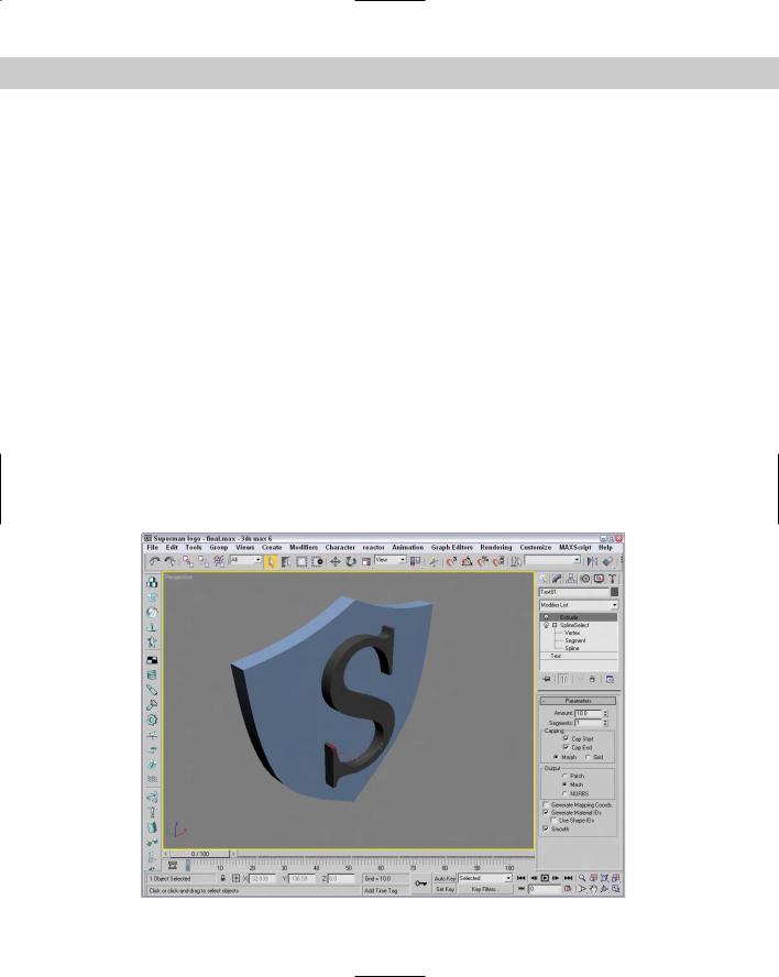
Figure 12-8 shows the resulting extruded S shape. The magic part of this example is that you can select the Text object in the Modifier Stack and change the letter S to B (for Batman) or A (for Aquaman), and the same modifier is applied to the new letter without your having to do any more work.
Figure 12-8: The Extrude modifier is applied to just the subobject selection.