

Chapter 2 Seeing It All — Working with the Viewports |
71 |
If you tried this tutorial as outlined, try it again using the mouse’s scroll wheel.
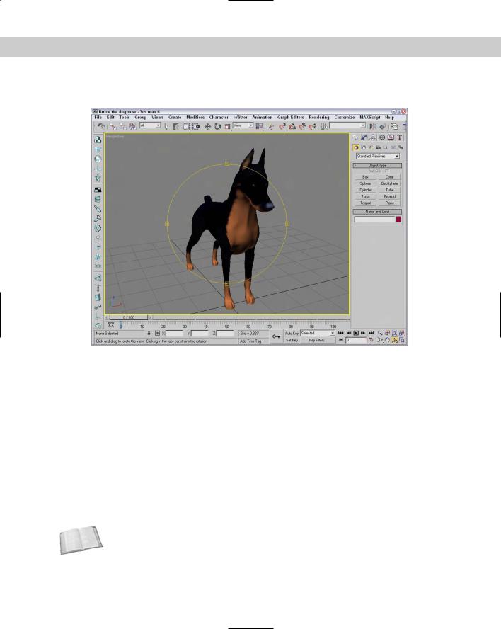
Figure 2-7: The Perspective viewport after a slight rotation shows Bruce’s good side.
Configuring the Viewports
If the Viewport Navigation Controls help define what you see, then the Viewport Configuration dialog box helps define how you see objects in the viewports. You can configure each viewport using this dialog box. To open this dialog box, choose the Customize Viewport Configuration menu command. You can also open this dialog box by right-clicking the viewport’s name located in the upper-left corner of each viewport and choosing Configure from the pop-up menu. The pop-up menu itself includes many of the settings found in the Viewport Configuration dialog box, but the dialog box lets you alter several settings at once. You can also make this dialog box appear for the active viewport by right-clicking any of the Viewport Navigation Control buttons in the lower-right corner.
The Viewport Configuration dialog box contains several panels, including Rendering Method, Layout, Safe Frames, Adaptive Degradation, and Regions. The Preference Settings dialog box also includes many settings for controlling the behavior and look of the viewports.
Cross- |
See Chapter 4, “Customizing the Max Interface and Setting Preferences” for more on the |
Reference |
Preference Settings dialog box and all its options. |
|
72 |
Part I Learning the Max Interface |
|
Setting the viewport rendering method |
|
Complex scenes take longer to display and render. The renderer used for the viewports is |
|
highly optimized to be very quick, but if you’re working on a huge model with lots of complex |
|
textures and every viewport is set to display the highest quality view, then updating each |
|
viewport can slow the program to a crawl. The Viewport Configuration dialog box’s |
|
Rendering Method panel, shown in Figure 2-8, lets you set the rendering settings for the |
|
Active Viewport, All Viewports, or All but Active viewport. |
Tip |
If you ever get stuck waiting for Max to complete a task, such as redrawing the viewports, you |
|
can always press the Escape key to immediately suspend any task and return control to the |
|
interface. |
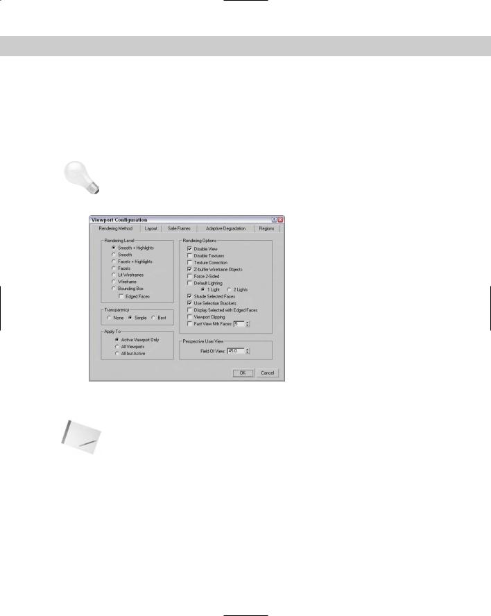
Figure 2-8: The Rendering Method panel holds controls for specifying the Rendering Level and several other rendering options.
Note These settings have no effect on the final rendering specified using the Rendering menu. They affect only the display in the viewport.
Rendering levels
The Rendering Level options, from slowest to fastest, include the following:
Smooth+Highlights: Shows smooth surfaces with lighting highlights. This rendering type is the slowest.
Smooth: Shows smooth surfaces without any lighting effects.
Facets+Highlights: Shows individual polygon faces and lighting highlights.
Facets: Shows individual polygon faces without any lighting effects.
Chapter 2 Seeing It All — Working with the Viewports |
73 |
Lit Wireframes: Shows polygon edges with lighting effects.
Wireframe: Shows polygon edges only.
Bounding Box: Shows a box that would enclose the object. This rendering type is the quickest.
Note |
Although it really isn’t a rendering method, the Edged Faces option shows the edges for each |
|
face when a shaded rendering method is selected. You can enable and disable this option |
|
with the F4 keyboard shortcut. |
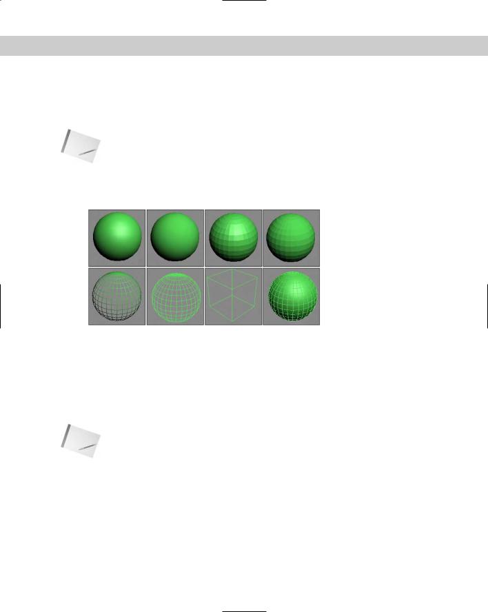
Figure 2-9 shows, side by side, all the various viewport rendering methods applied to a simple sphere.
Figure 2-9: The viewport rendering methods from left to right are
First Row: Smooth+Highlights, Smooth, Facets+Highlights, Facets.
Second Row: Lit Wireframes, Wireframe, Bounding Box, and
Edged Faces applied to Smooth+Highlights.
The most common rendering setting is Wireframe. It gives a good representation of the object while redrawing very quickly. Faceted rendering displays every face as a flat plane, but it shows the object as a solid model and is good for checking whether objects overlap. The Smooth rendering level shows a rough approximation of the final rendering. Setting the rendering level to include highlights shows the effect of the lights in the scene.
Note Many effects, such as bump maps, transparent maps, and shadows, cannot be seen in the viewport and show up only in the final render.
Viewing transparency
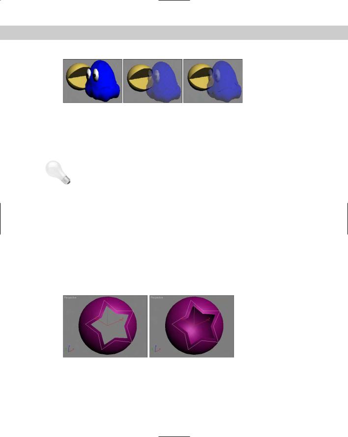
In addition to these shading types, you can set the viewport to display objects that contain transparency (which is set in the Object Properties dialog box). The three Transparency options are None, which doesn’t display any transparency; Simple, which cross-hatches the transparent object; and Best, which includes a transparency effect for a smooth look. Figure 2-10 shows these three transparency options with the help of a Pacman-like creature and his ghostly rival.
74 |
Part I Learning the Max Interface |
|
Figure 2-10: The viewport transparency options include None, Simple, |
|
and Best. |
|
Rendering options |
|
The Rendering Options section within the Rendering Method panel includes several other |
|
options, such as Disable View (D) and Disable Textures. These options can help speed up |
|
viewport updates or increase the visual detail of the objects in the viewport. |
Tip |
At any time during a viewport update, you can click the mouse or press a key to cancel the |
|
redraw. Max doesn’t make you wait for a screen redraw to be able to execute commands |
|
with the mouse or keyboard shortcuts. |
|
Disable Textures turns off texture rendering for quick viewport updates. The Texture |
|
Correction option speeds rendering updates by interpolating the current texture rather than |
|
re-rendering. Texture Correction (along with Disable View) is one of the options available in |
|
the pop-up menu by right-clicking the viewport name. |
|
A Z-Buffer is used to keep track of each object’s distance from the camera. Enabling Z-Buffer |
|
Wireframe Objects causes the wireframe objects to be drawn from back to front. If your wire- |
|
frame lines seem to be disappearing, it could be that the viewport is drawing the lines in |
|
whatever order and some lines that should appear in the back are being drawn on top of the |
|
ones in the front. Enabling this option helps prevent that. |
|
Force 2-Sided makes both sides of all faces visible. For example, suppose you have a sphere |
|
with a hole in it. This setting enables you to see the interior surface of the sphere through the |
|
hole. Figure 2-11 shows a sphere with a star-shape cutout of its surface. The left image has the |
|
Force 2-Sided option disabled, and the image on the right has it enabled. |
Figure 2-11: The Force 2-Sided option makes the interior of objects visible.
The Default Lighting toggle deactivates your current lights and uses the default lights. This option can be helpful when you’re trying to view objects in a dark setting because the default lighting illuminates the entire scene without requiring you to remove or turn off lights. You
Chapter 2 Seeing It All — Working with the Viewports |
75 |
can also specify whether default lighting uses one light or two. The one-light option creates a single light positioned behind the viewer and at an angle to the scene. Scenes with one light update quicker than scenes with two.
Making selected objects visible
You use Shade Selected Faces (F2) to shade selected subobject faces in red, making them easy to see.
Note The Shade Selected Faces (F2) option, which shades selected subobject faces, is different from the Views Shade Selected menu command, which turns on shading for the selected object in all viewports.
The Use Selection Brackets option displays white corners around the current selection. Selection brackets are useful for helping you see the entire size of a grouped object but can be annoying if left on with many objects selected. Uncheck this option (or press the J key) to make these brackets disappear.
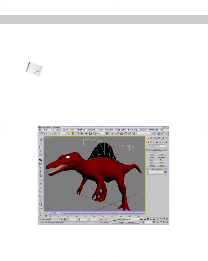
The option to Display Selected with Edged Faces helps to highlight the selected object. If this option is enabled, then the edges of the current selection are displayed regardless of whether the Edged Faces check box is enabled. Figure 2-12 shows a dinosaur with his upper fin selected with the Display Selected with Edged Faces option and the Use Selection Brackets options enabled. These options make the current selection easy to see.
Figure 2-12: The Display Selected with Edged Faces and Use Selection Brackets options make identifying the current selection easy.
76 |
Part I Learning the Max Interface |
Using clipping planes
Clipping planes define an invisible barrier beyond which all objects are invisible. For example, if you have a scene with many detailed mountain objects in the background, working with an object in the front of the scene can be difficult. By setting the clipping plane between the two, you can work on the front objects without having to redraw the mountain objects every time you update the scene. This affects only the viewport, not the rendered output.
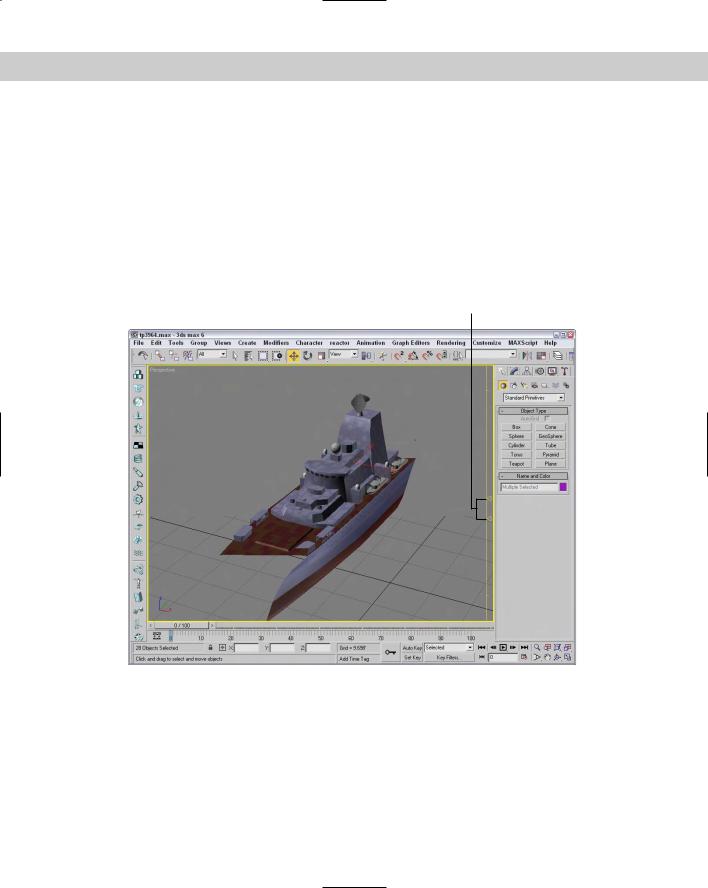
Enabling the Viewport Clipping option places a yellow line with two arrows on the right side of the viewport, as shown in Figure 2-13. The top arrow represents the back clipping plane, and the bottom arrow is the front clipping plane. Drag the arrows to set the clipping planes. You can quickly turn Viewport Clipping on or off by right-clicking the viewport name and choosing Viewport Clipping from the pop-up menu.
Clipping plane markers
Figure 2-13: The clipping planes can be used to hide the front and rear of this ship to focus on the center section.
Enabling Fast View
The Fast View option speeds viewport updates by drawing only a limited number of faces. The spinner value determines how often faces are drawn. For example, a setting of 5 would draw only every fifth face. This option renders viewport updates much quicker and gives you an idea of the objects without displaying the entire object.
Chapter 2 Seeing It All — Working with the Viewports |
77 |
Tutorial: Creating interesting patterns with the Fast View setting
You can use the Fast View setting in the Viewport Configuration dialog box to create some interesting patterns.
To create patterned spheres, follow these steps:
1.Open the Patterned sphere.max file from the Chap 02 directory on the CD-ROM. This file has a simple smooth sphere.
2.Click in the Top view, and choose Customize Viewport Configuration to open the Viewport Configuration dialog box. Select the Smooth Rendering Level and the Fast View Nth Faces options. Set the Fast View Nth Faces value to 2.
3.Repeat Step 2 for the Front, Left, and Perspective viewports, setting the Fast View Nth Faces values to 3, 4, and 5, respectively.
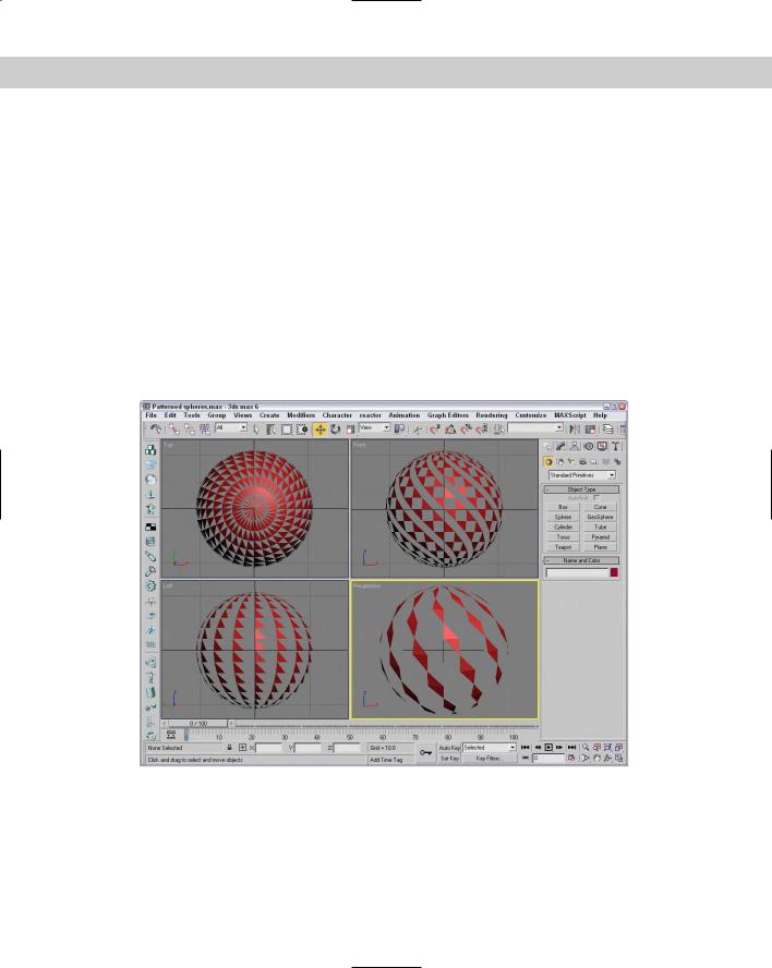
Figure 2-14 shows a sphere rendered using the Fast View option. Notice that the settings for each viewport can be different.
Figure 2-14: Cool patterns created with the Fast View setting in the Viewport Configuration dialog box
78 |
Part I Learning the Max Interface |
Note If any of these spheres were rendered using the Rendering menu, the entire sphere would be visible. The Fast View option affects only the viewport display.
Setting the Field of View
You can also alter the Field of View (FOV)for the Perspective view in the Viewport Configuration dialog box. To create a fish-eye view, increase the FOV setting to 10 or more. The maximum FOV value is 180, and the default value is 45. You can also change the Field of View using the Field of View button in the Viewport Navigation Controls. The Viewport Configuration dialog box, however, lets you enter precise values.
Cross- |
See Chapter 24, “Working with Cameras,” for more coverage on Field of View. |
Reference |
|
Grabbing a viewport image
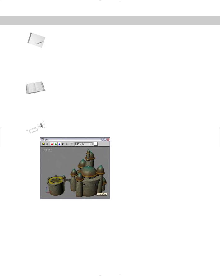
It’s not rendering, but you can grab an image of the active viewport using the Tools Grab Viewport. Before grabbing the image, a simple dialog box appears asking you to add a label to the grabbed image. The image is loaded into the Rendered Frame Window, and its label appears in the lower-right corner of the image, as shown in Figure 2-15.
New |
The Grab Viewport menu command is new to 3ds max 6. |
Feature |
|
Figure 2-15: A viewport image can be grabbed using a menu command found in the Tools menu.
Altering the Viewport layout
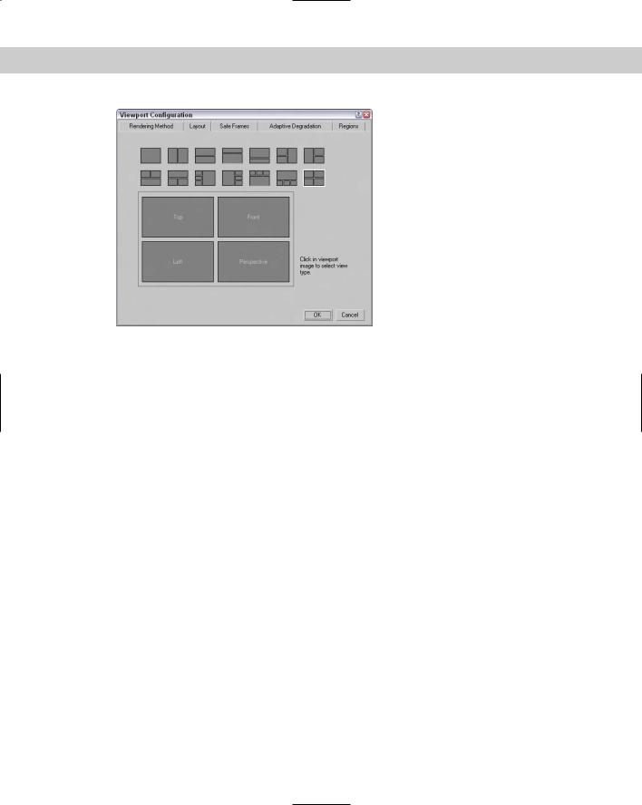
Now that you’ve started to figure out the viewports, you may want to change the number and size of viewports that are displayed. The Layout panel, shown in Figure 2-16, in the Viewpoint Configuration dialog box offers several layouts as alternatives to the default layout (not that there is anything wrong with the default and its four equally sized viewports).
Chapter 2 Seeing It All — Working with the Viewports |
79 |
Figure 2-16: The Layout panel offers many layout options.
After selecting a layout from the options at the top of the panel, you can assign each individual viewport a different view by clicking the viewport and choosing a view from the pop-up menu. The view options include Perspective, User, Front, Back, Top, Bottom, Left, Right, ActiveShade, Schematic, Grid (Front, Back, Top, Bottom, Left, Right, Display Planes), Extended (Asset Browser, MAXScript Listener), and Shape.
Views can also be set to Camera and Spotlight if they exist in the scene. Each camera and light that exists is listed by name at the top of the pop-up menu.
Using Safe Frames
Completing an animation and converting it to some broadcast medium, only to see that the whole left side of the animation is being cut off in the final screening, can be discouraging. If you rely on the size of the active viewport to show the edges of the final output, you could be way off. Using the Safe Frames feature, you can display some guides within the viewport that show where these clipping edges are.
The Safe Frames panel of the Viewport Configuration dialog box lets you define several safe frame options, as shown in Figure 2-17, including the following:
Live Area: Marks the area that will be rendered, shown as yellow lines. If a background image is added to the viewport and the Match Rendering Output option is selected, then the background image will fit within the Live Area.
Action Safe: The area ensured to be visible in the final rendered file, marked with light blue lines; objects outside this area will be at the edge of the television screen and could be distorted.
Title Safe: The area where the title can safely appear without distortion or bleeding, marked with orange lines.
User Safe: The output area defined by the user, marked with magenta lines.
12-Field Grid: Displays a grid in the viewport, marked with a pink grid.
80 |
Part I Learning the Max Interface |
Figure 2-17: The Safe Frames panel lets you specify areas to render.
For each type of safe frame, you can set the percent reduction by entering values in the Horizontal, Vertical, or Both fields. The 12-Field Grid option offers 4 × 3 and 12 × 9 aspect ratios.
The Show Safe Frames in Active View option displays the Safe Frame borders in the active viewport. You can quickly enable or disable Safe Frames by right-clicking the viewport name and choosing Show Safe Frame in the pop-up menu (or you can use the Shift+F keyboard shortcut).
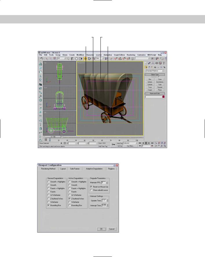
Figure 2-18 shows an elongated Perspective viewport with all the safe frame guides enabled. The Safe Frames show that the top and bottom of my covered wagon will be cut off whe rendered.
Understanding Adaptive Degradation
When you are previewing a complex animation sequence in a viewport, slow updates can affect the timing of the animation. This can make proofing your work difficult and would require many additional, fully rendered tasks. The feature in Max that addresses this issue is called Adaptive Degradation, and although it sounds like a weapon that some alien would use to disarm you, it enables you to force a viewport to display at a prespecified number of
frames per second. If the display update takes too long to maintain this rate, then it automatically degrades the rendering level in order to maintain the frame rate. This option is very helpful because when you’re testing an animation, you are not as concerned about the model details or textures.
The Adaptive Degradation panel is available in the Viewport Configuration dialog box, as shown in Figure 2-19.
Chapter 2 Seeing It All — Working with the Viewports |
81 |
Action Safe lines |
Title Safe lines |
Live Area lines |
User Safe lines |
Figure 2-18: Safe frames provide guides that help you see when the scene objects are out of bounds.
Figure 2-19: The Adaptive Degradation panel maintains a defined frame rate by degrading the rendering level.
82 |
Part I Learning the Max Interface |
|
You can enable Adaptive Degradation by using the Views Adaptive Degradation menu |
|
command (or by pressing the O key). Adaptive Degradation, when enabled, is used only for |
|
animation sequences where the objects are updated within the viewport quickly. If the anima- |
|
tion isn’t progressing, then enabling and disabling Adaptive Degradation has no effect. |
Cross- |
You learn to animate objects in Chapter 30, “Animation Basics.” |
Reference |
|
|
You enter the frame rate that you want to maintain into the Maintain FPS box in the Degrade |
|
Parameters section. The General Degradation selection specifies the render level used by all |
|
inactive viewports; the Active Degradation selection is used by the active viewport. You can |
|
select several rendering levels in each section. |
Tip |
Another way to speed the frame rate in the active viewport is to disable (D) the inactive |
|
viewports. |
The Reset on Mouse Up option forces Max to render at the specified rendering levels when the mouse is released. The Show Rebuild Cursor option makes the cursor visible as the viewports are rendered. The Update Time is the amount of time between rendering updates.
At a setting of 0, each frame must be completely rendered before the next frame is attempted. The Interrupt Time value is how long Max waits before checking to see whether the mouse has moved.
Defining regions
Regions, the final panel in the Viewport Configuration dialog box, enables you to define regions and focus your rendering energies on a smaller area. Complex scenes can take considerable time and machine power to render. Sometimes, you want to test render only a portion of a viewport to check material assignment, texture map placement, or lighting.
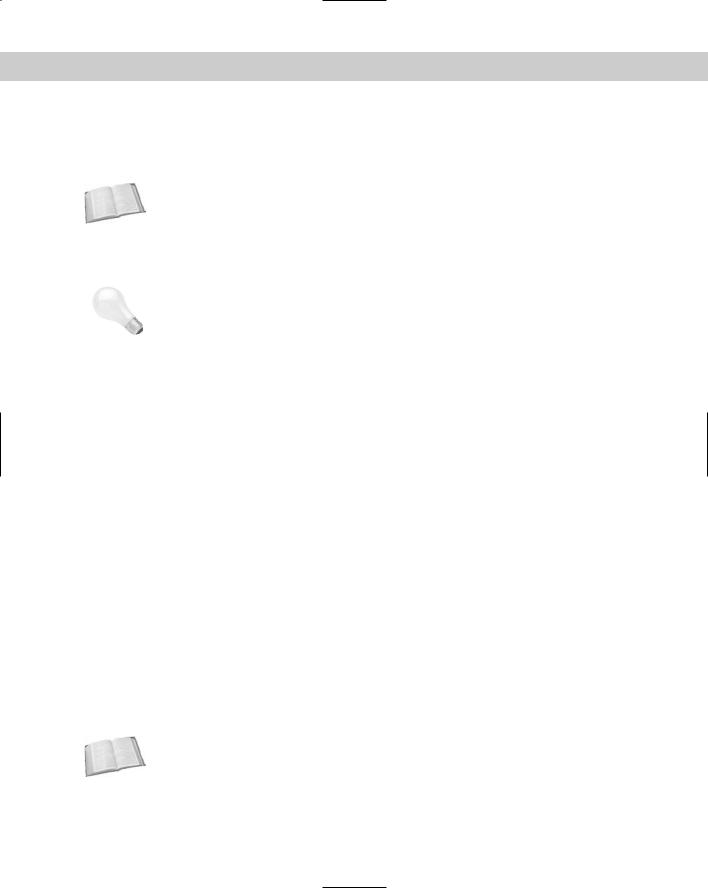
You can define the size of the various Regions in the Regions panel of the Viewport Configuration dialog box, shown in Figure 2-20.
After you’ve specified a Blowup Region or a Sub Region, you can select to render using these regions by selecting Region or Blowup from the Render Type drop-down list on the far-right end of the main toolbar and clicking the Quick Render button. After clicking the Quick Render button, the specified region is displayed as an outline in the viewport and an OK button appears in the lower-right corner of the viewport. You can move this outline to reposition
it or drag its edge or corner handles to resize the region. The new position and dimension values are updated in the Regions panel for next time. Click the OK button to begin the rendering process.
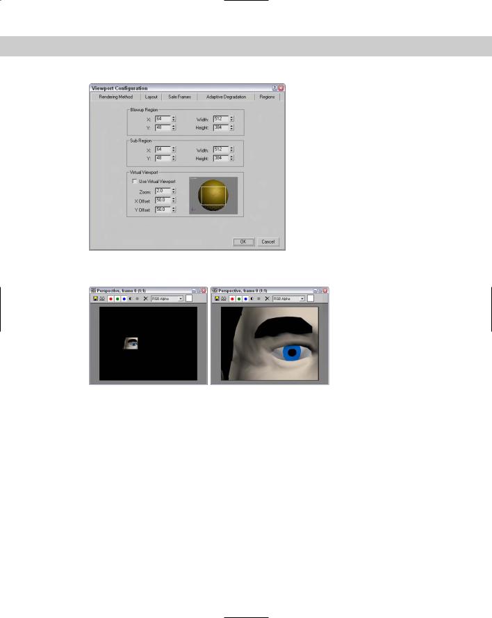
The difference between these two regions is that the Sub Region displays the Rendered Frame Window in black except for the specified sub-region. The Blowup Region fills the entire Rendered Frame Window, as shown in Figure 2-21.
Cross- |
You can learn more about Render Types and the Rendered Frame Window in Chapter 41, |
Reference |
“Rendering Basics.” |
|
Chapter 2 Seeing It All — Working with the Viewports |
83 |
Figure 2-20: The Regions panel enables you to work with smaller regions within your scene.
Figure 2-21: The image on the left was rendered using the
Sub Region option; the right image used the Blowup Region.
The Virtual Viewport is a feature that lets you zoom in and pan within the viewport image using the numeric keypad. This feature is available only if you are using the OpenGL display driver. You can check to see which display driver you are using by selecting Help About 3ds max. This command opens a credits screen that lists the current driver. You can change the current display driver in the Viewport panel of the Preference Settings dialog box.
If you have OpenGL set up as the current display driver, then you can select Use Virtual Viewport to display the viewport in the area to the right. Using the Zoom, X, and Y Offset values, you can specify where the Virtual Viewport looks or you can drag the rectangular outline in the visible screen to the right.