

- •Preface
- •About This Book
- •Acknowledgments
- •Contents at a Glance
- •Contents
- •Relaxing at the Beach
- •Dressing the Scene
- •Animating Motion
- •Rendering the Final Animation
- •Summary
- •The Interface Elements
- •Using the Menus
- •Using the Toolbars
- •Using the Viewports
- •Using the Command Panel
- •Using the Lower Interface Bar Controls
- •Interacting with the Interface
- •Getting Help
- •Summary
- •Understanding 3D Space
- •Using the Viewport Navigation Controls
- •Configuring the Viewports
- •Working with Viewport Backgrounds
- •Summary
- •Working with Max Scene Files
- •Setting File Preferences
- •Importing and Exporting
- •Referencing External Objects
- •Using the File Utilities
- •Accessing File Information
- •Summary
- •Customizing Modify and Utility Panel Buttons
- •Working with Custom Interfaces
- •Configuring Paths
- •Selecting System Units
- •Setting Preferences
- •Summary
- •Creating Primitive Objects
- •Exploring the Primitive Object Types
- •Summary
- •Selecting Objects
- •Setting Object Properties
- •Hiding and Freezing Objects
- •Using Layers
- •Summary
- •Cloning Objects
- •Understanding Cloning Options
- •Mirroring Objects
- •Cloning over Time
- •Spacing Cloned Objects
- •Creating Arrays of Objects
- •Summary
- •Working with Groups
- •Building Assemblies
- •Building Links between Objects
- •Displaying Links and Hierarchies
- •Working with Linked Objects
- •Summary
- •Using the Schematic View Window
- •Working with Hierarchies
- •Setting Schematic View Preferences
- •Using List Views
- •Summary
- •Working with the Transformation Tools
- •Using Pivot Points
- •Using the Align Commands
- •Using Grids
- •Using Snap Options
- •Summary
- •Exploring the Modifier Stack
- •Exploring Modifier Types
- •Summary
- •Exploring the Modeling Types
- •Working with Subobjects
- •Modeling Helpers
- •Summary
- •Drawing in 2D
- •Editing Splines
- •Using Spline Modifiers
- •Summary
- •Creating Editable Mesh and Poly Objects
- •Editing Mesh Objects
- •Editing Poly Objects
- •Using Mesh Editing Modifiers
- •Summary
- •Introducing Patch Grids
- •Editing Patches
- •Using Modifiers on Patch Objects
- •Summary
- •Creating NURBS Curves and Surfaces
- •Editing NURBS
- •Working with NURBS
- •Summary
- •Morphing Objects
- •Creating Conform Objects
- •Creating a ShapeMerge Object
- •Creating a Terrain Object
- •Using the Mesher Object
- •Working with BlobMesh Objects
- •Creating a Scatter Object
- •Creating Connect Objects
- •Modeling with Boolean Objects
- •Creating a Loft Object
- •Summary
- •Understanding the Various Particle Systems
- •Creating a Particle System
- •Using the Spray and Snow Particle Systems
- •Using the Super Spray Particle System
- •Using the Blizzard Particle System
- •Using the PArray Particle System
- •Using the PCloud Particle System
- •Using Particle System Maps
- •Controlling Particles with Particle Flow
- •Summary
- •Understanding Material Properties
- •Working with the Material Editor
- •Using the Material/Map Browser
- •Using the Material/Map Navigator
- •Summary
- •Using the Standard Material
- •Using Shading Types
- •Accessing Other Parameters
- •Using External Tools
- •Summary
- •Using Compound Materials
- •Using Raytrace Materials
- •Using the Matte/Shadow Material
- •Using the DirectX 9 Shader
- •Applying Multiple Materials
- •Material Modifiers
- •Summary
- •Understanding Maps
- •Understanding Material Map Types
- •Using the Maps Rollout
- •Using the Map Path Utility
- •Using Map Instances
- •Summary
- •Mapping Modifiers
- •Using the Unwrap UVW modifier
- •Summary
- •Working with Cameras
- •Setting Camera Parameters
- •Summary
- •Using the Camera Tracker Utility
- •Summary
- •Using Multi-Pass Cameras
- •Creating Multi-Pass Camera Effects
- •Summary
- •Understanding the Basics of Lighting
- •Getting to Know the Light Types
- •Creating and Positioning Light Objects
- •Viewing a Scene from a Light
- •Altering Light Parameters
- •Working with Photometric Lights
- •Using the Sunlight and Daylight Systems
- •Using Volume Lights
- •Summary
- •Selecting Advanced Lighting
- •Using Local Advanced Lighting Settings
- •Tutorial: Excluding objects from light tracing
- •Summary
- •Understanding Radiosity
- •Using Local and Global Advanced Lighting Settings
- •Working with Advanced Lighting Materials
- •Using Lighting Analysis
- •Summary
- •Using the Time Controls
- •Working with Keys
- •Using the Track Bar
- •Viewing and Editing Key Values
- •Using the Motion Panel
- •Using Ghosting
- •Animating Objects
- •Working with Previews
- •Wiring Parameters
- •Animation Modifiers
- •Summary
- •Understanding Controller Types
- •Assigning Controllers
- •Setting Default Controllers
- •Examining the Various Controllers
- •Summary
- •Working with Expressions in Spinners
- •Understanding the Expression Controller Interface
- •Understanding Expression Elements
- •Using Expression Controllers
- •Summary
- •Learning the Track View Interface
- •Working with Keys
- •Editing Time
- •Editing Curves
- •Filtering Tracks
- •Working with Controllers
- •Synchronizing to a Sound Track
- •Summary
- •Understanding Your Character
- •Building Bodies
- •Summary
- •Building a Bones System
- •Using the Bone Tools
- •Using the Skin Modifier
- •Summary
- •Creating Characters
- •Working with Characters
- •Using Character Animation Techniques
- •Summary
- •Forward versus Inverse Kinematics
- •Creating an Inverse Kinematics System
- •Using the Various Inverse Kinematics Methods
- •Summary
- •Creating and Binding Space Warps
- •Understanding Space Warp Types
- •Combining Particle Systems with Space Warps
- •Summary
- •Understanding Dynamics
- •Using Dynamic Objects
- •Defining Dynamic Material Properties
- •Using Dynamic Space Warps
- •Using the Dynamics Utility
- •Using the Flex Modifier
- •Summary
- •Using reactor
- •Using reactor Collections
- •Creating reactor Objects
- •Calculating and Previewing a Simulation
- •Constraining Objects
- •reactor Troubleshooting
- •Summary
- •Understanding the Max Renderers
- •Previewing with ActiveShade
- •Render Parameters
- •Rendering Preferences
- •Creating VUE Files
- •Using the Rendered Frame Window
- •Using the RAM Player
- •Reviewing the Render Types
- •Using Command-Line Rendering
- •Creating Panoramic Images
- •Getting Printer Help
- •Creating an Environment
- •Summary
- •Creating Atmospheric Effects
- •Using the Fire Effect
- •Using the Fog Effect
- •Summary
- •Using Render Elements
- •Adding Render Effects
- •Creating Lens Effects
- •Using Other Render Effects
- •Summary
- •Using Raytrace Materials
- •Using a Raytrace Map
- •Enabling mental ray
- •Summary
- •Understanding Network Rendering
- •Network Requirements
- •Setting up a Network Rendering System
- •Starting the Network Rendering System
- •Configuring the Network Manager and Servers
- •Logging Errors
- •Using the Monitor
- •Setting up Batch Rendering
- •Summary
- •Compositing with Photoshop
- •Video Editing with Premiere
- •Video Compositing with After Effects
- •Introducing Combustion
- •Using Other Compositing Solutions
- •Summary
- •Completing Post-Production with the Video Post Interface
- •Working with Sequences
- •Adding and Editing Events
- •Working with Ranges
- •Working with Lens Effects Filters
- •Summary
- •What Is MAXScript?
- •MAXScript Tools
- •Setting MAXScript Preferences
- •Types of Scripts
- •Writing Your Own MAXScripts
- •Learning the Visual MAXScript Editor Interface
- •Laying Out a Rollout
- •Summary
- •Working with Plug-Ins
- •Locating Plug-Ins
- •Summary
- •Low-Res Modeling
- •Using Channels
- •Using Vertex Colors
- •Rendering to a Texture
- •Summary
- •Max and Architecture
- •Using AEC Objects
- •Using Architectural materials
- •Summary
- •Tutorial: Creating Icy Geometry with BlobMesh
- •Tutorial: Using Caustic Photons to Create a Disco Ball
- •Summary
- •mental ray Rendering System
- •Particle Flow
- •reactor 2.0
- •Schematic View
- •BlobMesh
- •Spline and Patch Features
- •Import and Export
- •Shell Modifier
- •Vertex Paint and Channel Info
- •Architectural Primitives and Materials
- •Minor Improvements
- •Choosing an Operating System
- •Hardware Requirements
- •Installing 3ds max 6
- •Authorizing the Software
- •Setting the Display Driver
- •Updating Max
- •Moving Max to Another Computer
- •Using Keyboard Shortcuts
- •Using the Hotkey Map
- •Main Interface Shortcuts
- •Dialog Box Shortcuts
- •Miscellaneous Shortcuts
- •System Requirements
- •Using the CDs with Windows
- •What’s on the CDs
- •Troubleshooting
- •Index
650 Part IV Materials and Maps
Figure 23-12: The Relax tool can make working with vertices easier.
Summary
We’ve covered lots of ground in this chapter because there are lots of different maps. Learning to use these maps will make a big difference in the realism of your materials.
In this chapter, you’ve learned about
The basics of mapping coordinates
Using mapping modifiers
Applying labels with the UVW Map modifier
Controlling mapping coordinates with the Unwrap UVW modifier
Displacing the surface with the Displace modifier
In the next part, you gain some experience using cameras.
|
|
|
P A R T
Cameras
V
In This Part
Chapter 24
Working with Cameras
Chapter 25
Matching and Tracking
Cameras
Chapter 26
Multi-Pass Camera
Effects


Working with
Cameras
Do you remember as a kid when you first got your own camera? After taking the usual pictures of your dog and the neighbor’s fence, you quickly learned how much fun you could have with cam-
era placement, such as a picture of a flagpole from the top of the flagpole or your mom’s timeless expression when she found you inside the dryer. Cameras in Max can also offer all kinds of amusing views of your scene.
The benefit of cameras is that you can position them anywhere within a scene to offer a custom view. You can open camera views in a viewport, and you can also use them to render images or animated sequences. Cameras in Max can also be animated (without damaging the camera, even if your mischievous older brother turns on the dryer).
Working with Cameras
If you’re a photography hobbyist or like to take your video camera out and shoot your own footage, then many of the terms in this section will be familiar to you. The cameras used in Max to get custom views of a scene behave in many respects just like real-world cameras.
Max and real-world cameras both work with different lens settings, which are measured and defined in millimeters. You can select from a variety of preset stock lenses, including 35mm, 80mm, and even 200mm. Max cameras also offer complete control over the camera’s focal length, field of view, and perspective for wide-angle or telephoto shots. The big difference is that you never have to worry about focusing a lens, setting flashes, or loading film.
Light coming into a camera is bent through the camera lens and focused on the film, where the image is captured. The distance between the film and the lens is known as the focal length. This distance is measured in millimeters, and you can change it by switching to a different lens. On a camera that shoots 35mm film, a lens with a focal length of 50mm produces a view similar to what your eyes would see. A lens with a focal length less than 50mm is known as a wide-angle lens because it displays a wider view of the scene. A lens longer than 50mm is called a telephoto lens because it has the ability to give a closer view of objects for more detail, as a telescope does.
24C H A P T E R
In This Chapter
Understanding camera basics
Creating a camera object
Viewing a camera in a viewport
Controlling cameras with the viewport camera controls
Aiming a camera at objects
Altering camera parameters
Using the Camera
Correction modifier

654 Part V Cameras
Field of view is directly related to focal length and is a measurement of how much of the scene is visible. It is measured in degrees. The shorter the focal length, the wider the field of view.
When we look at a scene, objects appear larger if they are up close than they would lying at a farther distance. This effect is referred to as perspective and helps us to interpret distances. As mentioned, a 50mm lens gives a perspective similar to what our eyes give. Images taken with a wide field of view look distorted because the effect of perspective is increased.
Creating a Camera Object
To create a camera object, you can use the Create Cameras menu or open the familiar Create panel and click the Cameras category button. The two different types of cameras that you can create are a Free camera and a Target camera.
Camera objects are visible as icons in the viewports, but they aren’t rendered. The camera icon looks like a box with a smaller box in front of it, which represents the lens or front end of the camera. Both the Free and Target camera types can include a cone that shows where the camera is pointing.
Free camera
The Free camera object offers a view of the area that is directly in front of the camera and is the better choice if the camera will be animated. When a Free camera is initially created, it points at the negative Z axis of the active viewport. The single parameter for Free cameras defines a Target Distance — the distance to an invisible target about which the camera can orbit.
Target camera
A Target camera always points at a controllable target point some distance in front of the camera. Target cameras are easy to aim and are useful for situations where the camera won’t move. To create this type of camera, click a viewport to position the camera and drag to the location of its target. The target can be named along with the camera. When a target is created, Max automatically names the target by attaching “.target” to the end of the camera name. You can change this default name by typing a different name in the Name field.
Creating a Camera View
You can change any viewport to show a camera’s viewpoint. To do so, right-click the viewport’s title, and select View and the camera’s name from the pop-up menu. Any movements done to the camera are reflected immediately in the viewport.
Another way to select a camera for a viewport is to press the C key. This keyboard shortcut makes the active viewport into a camera view. If several cameras exist in a scene, then the Select Camera dialog box appears, from which you can select a camera to use. Figure 24-1 shows two Target cameras pointing at a car. The two viewports on the right are the views from these cameras.
You can turn off the camera object icons using the Display panel. In the Display panel, under the Hide by Category rollout, select the Cameras option. When selected, the camera icons are not visible in the viewports.
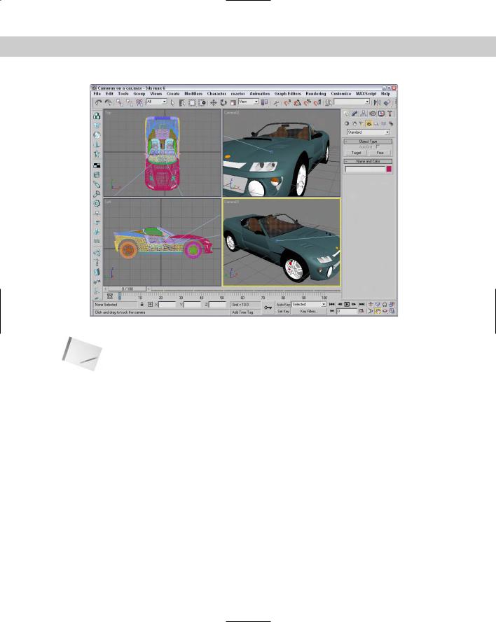
Chapter 24 Working with Cameras 655
|
Figure 24-1: A car as seen by two different cameras |
Note |
Cameras are usually positioned at some distance away from the rest of the scene. Their dis- |
|
tant position can make scene objects appear very small when the Zoom Extents button is |
|
used. If the visibility of the camera icons is turned off, Zoom Extents does not include them |
|
in the zoom. You could also enable the Ignore Extents option in the camera’s Object |
|
Properties dialog box. |
|
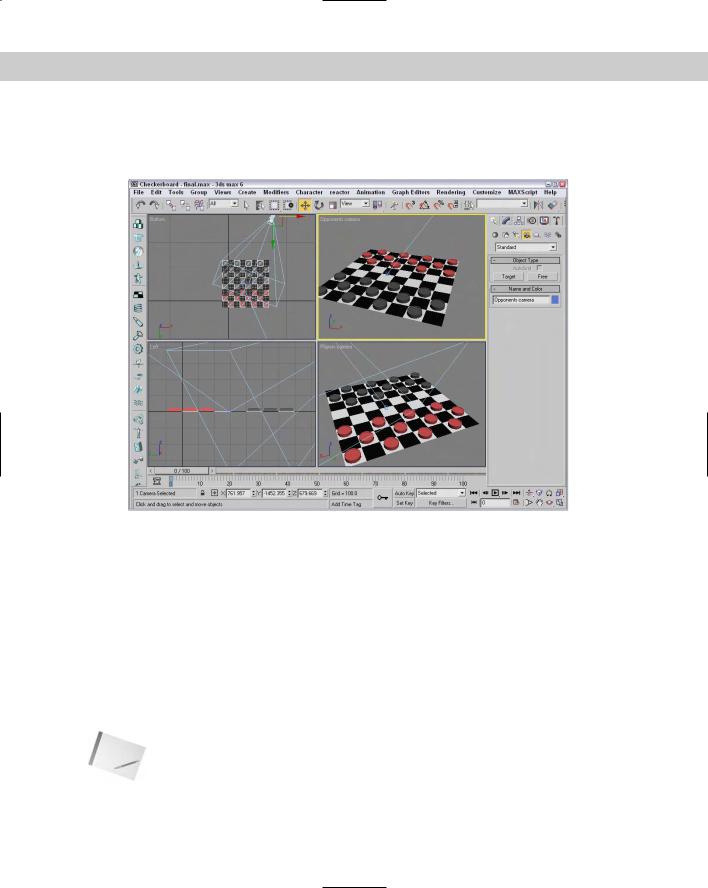
Tutorial: Setting up an opponent’s view |
|
There is no limit to the number of cameras that you can place in a scene. Placing two cam- |
|
eras in a scene showing a game of checkers lets you see the game from the perspective of |
|
either player. |
|
To create a new aligned view from the opponent’s perspective, follow these steps: |
1.Open the Checkers game.max file from the Chapter 24 directory on the CD-ROM.
2.Select Create Cameras Target Camera and drag in the Top viewport to create the camera. Then give the new camera the name Opponents Camera.
3.Position the new target camera behind the opponent’s pieces roughly symmetrical to the other camera.
4.With the new camera selected, drag the target point and position it on top of the other camera’s target point somewhere below the center of the board.
656 Part V Cameras
To see the new camera view, right-click the Perspective viewport title and choose View Black Camera (or select the camera and the Perspective viewport, and press the C key). Figure 24-2 shows the view from this camera.
Figure 24-2: Positioning an additional camera behind the Black player’s pieces offers the opponent’s view.
Controlling a camera
I was once on a ride at Disneyland when a person behind me decided to blatantly disregard the signs not to take photographs. As he leaned over to snap another picture, I heard a fumbling noise, a faint, “Oh no,” and then the distinct sound of his camera falling into the depths of the ride. (That was actually more enjoyable than the ride. It served him right.) As this example shows, controlling a camera can be difficult. This chapter offers many tips and tricks for dealing with the cameras in Max, and you won’t have to worry about dropping them.
You control the camera view in a viewport by means of the Camera Navigation controls located in the lower-right corner of the screen. These controls replace the viewport controls when a camera view is selected and are different from the normal Viewport Navigation controls. The Camera Navigation controls are identified and defined in Table 24-1.
Note |
Many of these controls are identical to the controls for lights. |
Chapter 24 Working with Cameras 657
You can constrain the movements to a single axis by holding down the Shift key. The Ctrl key causes the movements to increase rapidly. For example, holding down the Ctrl key while dragging the Perspective tool magnifies the amount of perspective applied to the viewport.
You can undo changes in the normal viewports using the Views Undo command, but you undo camera viewport changes with the regular Edit Undo command.
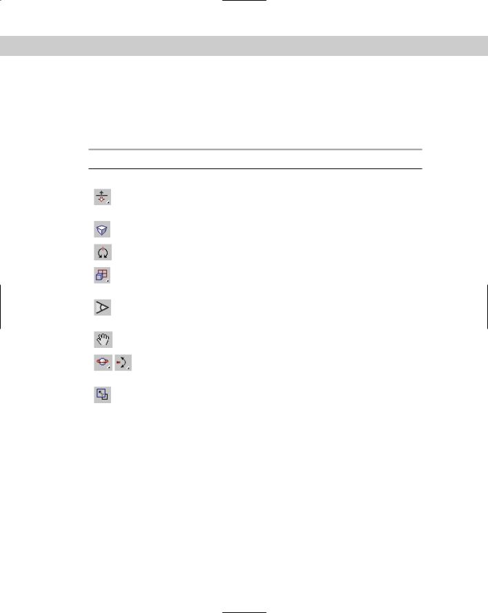
Table 24-1: Camera Navigation Control Buttons
Control Button |
Name |
Description |
|
|
|
|
Dolly Camera, |
Moves the camera, its target, or both the camera and |
|
Dolly Target, |
its target closer to or farther away from the scene in |
|
Dolly Camera + Target |
the direction it is pointing. |
|
Perspective |
Increases or decreases the viewport’s perspective by |
|
|
dollying the camera and altering its field of view. |
|
Roll Camera |
Spins the camera about its local Z axis. |
|
Zoom Extents All, |
Zooms in on all objects or the selected objects by |
|
Zoom Extents All Selected |
reducing the field of view until the objects fill the |
|
|
viewport. |
|
Field of View |
Changes the width of the view, similar to changing |
|
|
the camera lens or zooming without moving the |
|
|
camera. |
|
Truck Camera |
Moves the camera perpendicular to the line of sight. |
|
Orbit, Pan Camera |
The Orbit button rotates the camera around the |
|
|
target, and the Pan button rotates the target around |
|
|
the camera. |
|
Min/Max Toggle |
Makes the current viewport fill the screen. Clicking |
|
|
this button a second time returns the display to |
|
|
several viewports. |
|
|
|
Aiming a camera
In addition to the Camera Navigation buttons, you can use the Transformation buttons on the main toolbar to reposition the camera object. To move a camera, select the camera object and click the Select and Move button (W). Then drag in the viewports to move the camera.
Using the Select and Rotate (E) button changes the direction in which a camera points, but only Free cameras rotate in all directions. When applied to a Target camera, the rotate transformation spins only the camera about the axis pointing to the target. You aim Target cameras by moving their targets.
658 Part V Cameras
Note Don’t try to rotate a Target camera so that it is pointing directly up or down, or the camera will flip.
Select the target for a Target camera by selecting its camera object, right-clicking to open the pop-up menu, and selecting Select Target.
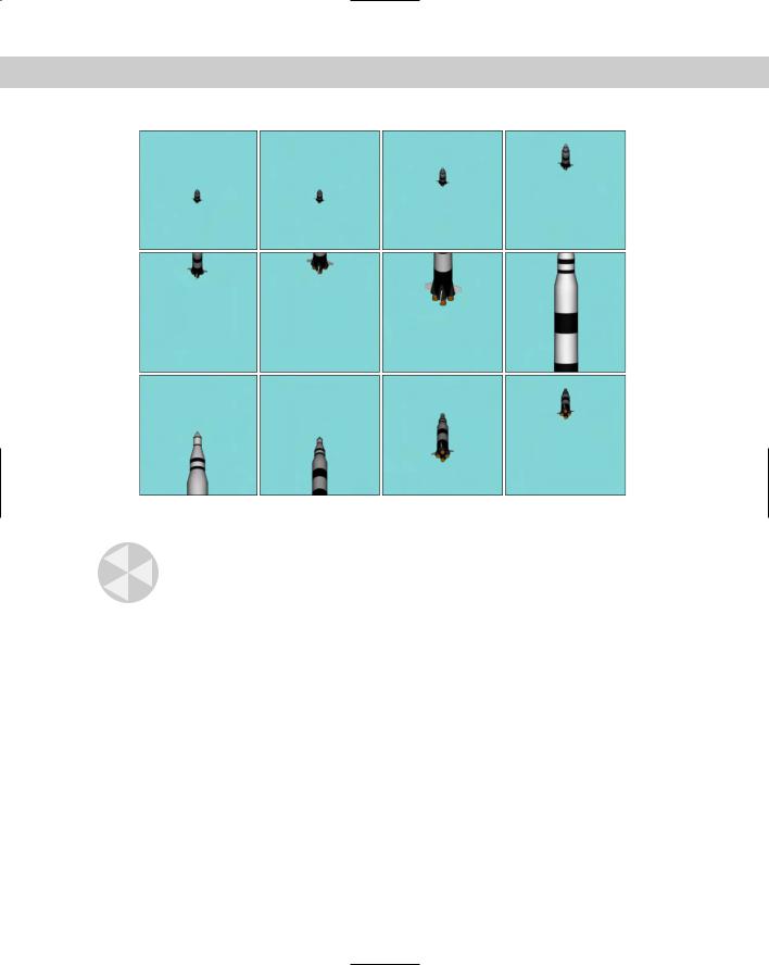
Tutorial: Watching a rocket
Because cameras can be transformed like any other geometry, they can also be set to watch the movements of any other geometry. In this tutorial, we aim a camera at a distant rocket and watch it as it flies past us and on into the sky. Zygote Media created the rocket model used in this tutorial.
To aim a camera at a rocket as it hurtles into the sky, follow these steps:
1.Open the Following a rocket.max file from the Chap 24 directory on the CD-ROM. This file includes a rocket mesh.
2.Select Create Cameras Target Camera and drag in the Front viewport from the top to the bottom of the viewport to create a camera. Set the Field of View value to 2.0 degrees. The corresponding Lens value is around 1031mm.
3.Select the camera target, click the Select and Link button in the main toolbar, and drag from the target to the rocket object.
4.To view the scene from the camera’s viewpoint, right-click the Perspective viewport title and choose Views Camera01 from the pop-up menu (or press the C button). Then click the Play Animation button to see how well the camera follows the target.
Figure 24-3 shows some frames from this animation.
Aligning cameras
Another way to aim a camera is with the Tools Align Camera menu command or by clicking the Align Camera button on the main toolbar (under the Align flyout). After
selecting this command, click an object face and hold down the mouse button; the normal to the object face that is currently under the cursor icon is displayed as a blue arrow. When you’ve located the point at which you want the camera to point, release the mouse button. The camera is repositioned to point directly at the selected point on the selected face along the normal.
Cross- |
The Align Camera command does the same thing for cameras that the Place Highlight com- |
Reference |
mand does for lights. A discussion of the Place Highlight command appears in Chapter 27, |
|
|
|
“Basic Lighting Techniques.” |
Cameras can be automatically positioned to match any view that a viewport can display, including lights and the Perspective view. To do this, select a camera, activate the viewport with the view that you want to match, and choose Views Match Camera to View (Ctrl+C). The camera is moved to display this view.
Chapter 24 Working with Cameras 659
Figure 24-3: Positioning the camera’s target on the rocket enables the camera to follow the rocket’s ascent.
Caution |
If you use the Match Camera to View command while a camera view is the active viewport, |
|
the two cameras are positioned on top of each other. |
Tutorial: Seeing the dinosaur’s good side
Using the Align Camera tool, you can place a camera so that it points directly at an item or the face of an object, such as the dinosaur’s good side (if a dinosaur has a good side). To align a camera with an object point, follow these steps:
1.Open the Dinosaur.max from the Chap 24 directory on the CD-ROM. This file includes a dinosaur model created by Viewpoint Datalabs.
2.Select Create Cameras Free Camera, and click in the Top viewport to create a new Free camera in the scene.
3.With the camera selected, choose Tools Align Camera or click the Align Camera flyout button on the main toolbar.
The cursor changes to a small camera icon.
660 Part V Cameras
4.Click the cursor on the dinosaur’s face just under its eye in the Perspective viewport. This point is where the camera will point.
5.To see the new camera view, right-click the viewport title and choose Views Camera01 (or press C). Although the camera is pointing at the selected point, you may need to change the field of view to correct the zoom ratios.
Figure 24-4 shows our dinosaur from the newly aligned camera.
Figure 24-4: This new camera view of the dinosaur shows his best side.
The Align Camera command points a camera at an object only for the current frame. It does not follow an object if it moves during an animation. To have a camera follow an object, you need to use the Look At Controller, which is covered later in this chapter.
The Align Camera command requires that a camera be selected before the command is used. Max includes another command that creates the camera for you and matches it to the current active viewport. The Views Create Camera From View (Ctrl+C) menu command creates a new free camera if one doesn’t already exist, matches the current active viewport, and makes the active viewport a camera view. This provides you the ability to position the view using the Viewport Navigation Controls and automatically make a camera that shows that view.
If a camera already exists in the scene and is selected, this command uses the selected camera for the view.
New |
The Create Camera From View command is new to 3ds max 6. |
Feature |
|