

- •Preface
- •About This Book
- •Acknowledgments
- •Contents at a Glance
- •Contents
- •Relaxing at the Beach
- •Dressing the Scene
- •Animating Motion
- •Rendering the Final Animation
- •Summary
- •The Interface Elements
- •Using the Menus
- •Using the Toolbars
- •Using the Viewports
- •Using the Command Panel
- •Using the Lower Interface Bar Controls
- •Interacting with the Interface
- •Getting Help
- •Summary
- •Understanding 3D Space
- •Using the Viewport Navigation Controls
- •Configuring the Viewports
- •Working with Viewport Backgrounds
- •Summary
- •Working with Max Scene Files
- •Setting File Preferences
- •Importing and Exporting
- •Referencing External Objects
- •Using the File Utilities
- •Accessing File Information
- •Summary
- •Customizing Modify and Utility Panel Buttons
- •Working with Custom Interfaces
- •Configuring Paths
- •Selecting System Units
- •Setting Preferences
- •Summary
- •Creating Primitive Objects
- •Exploring the Primitive Object Types
- •Summary
- •Selecting Objects
- •Setting Object Properties
- •Hiding and Freezing Objects
- •Using Layers
- •Summary
- •Cloning Objects
- •Understanding Cloning Options
- •Mirroring Objects
- •Cloning over Time
- •Spacing Cloned Objects
- •Creating Arrays of Objects
- •Summary
- •Working with Groups
- •Building Assemblies
- •Building Links between Objects
- •Displaying Links and Hierarchies
- •Working with Linked Objects
- •Summary
- •Using the Schematic View Window
- •Working with Hierarchies
- •Setting Schematic View Preferences
- •Using List Views
- •Summary
- •Working with the Transformation Tools
- •Using Pivot Points
- •Using the Align Commands
- •Using Grids
- •Using Snap Options
- •Summary
- •Exploring the Modifier Stack
- •Exploring Modifier Types
- •Summary
- •Exploring the Modeling Types
- •Working with Subobjects
- •Modeling Helpers
- •Summary
- •Drawing in 2D
- •Editing Splines
- •Using Spline Modifiers
- •Summary
- •Creating Editable Mesh and Poly Objects
- •Editing Mesh Objects
- •Editing Poly Objects
- •Using Mesh Editing Modifiers
- •Summary
- •Introducing Patch Grids
- •Editing Patches
- •Using Modifiers on Patch Objects
- •Summary
- •Creating NURBS Curves and Surfaces
- •Editing NURBS
- •Working with NURBS
- •Summary
- •Morphing Objects
- •Creating Conform Objects
- •Creating a ShapeMerge Object
- •Creating a Terrain Object
- •Using the Mesher Object
- •Working with BlobMesh Objects
- •Creating a Scatter Object
- •Creating Connect Objects
- •Modeling with Boolean Objects
- •Creating a Loft Object
- •Summary
- •Understanding the Various Particle Systems
- •Creating a Particle System
- •Using the Spray and Snow Particle Systems
- •Using the Super Spray Particle System
- •Using the Blizzard Particle System
- •Using the PArray Particle System
- •Using the PCloud Particle System
- •Using Particle System Maps
- •Controlling Particles with Particle Flow
- •Summary
- •Understanding Material Properties
- •Working with the Material Editor
- •Using the Material/Map Browser
- •Using the Material/Map Navigator
- •Summary
- •Using the Standard Material
- •Using Shading Types
- •Accessing Other Parameters
- •Using External Tools
- •Summary
- •Using Compound Materials
- •Using Raytrace Materials
- •Using the Matte/Shadow Material
- •Using the DirectX 9 Shader
- •Applying Multiple Materials
- •Material Modifiers
- •Summary
- •Understanding Maps
- •Understanding Material Map Types
- •Using the Maps Rollout
- •Using the Map Path Utility
- •Using Map Instances
- •Summary
- •Mapping Modifiers
- •Using the Unwrap UVW modifier
- •Summary
- •Working with Cameras
- •Setting Camera Parameters
- •Summary
- •Using the Camera Tracker Utility
- •Summary
- •Using Multi-Pass Cameras
- •Creating Multi-Pass Camera Effects
- •Summary
- •Understanding the Basics of Lighting
- •Getting to Know the Light Types
- •Creating and Positioning Light Objects
- •Viewing a Scene from a Light
- •Altering Light Parameters
- •Working with Photometric Lights
- •Using the Sunlight and Daylight Systems
- •Using Volume Lights
- •Summary
- •Selecting Advanced Lighting
- •Using Local Advanced Lighting Settings
- •Tutorial: Excluding objects from light tracing
- •Summary
- •Understanding Radiosity
- •Using Local and Global Advanced Lighting Settings
- •Working with Advanced Lighting Materials
- •Using Lighting Analysis
- •Summary
- •Using the Time Controls
- •Working with Keys
- •Using the Track Bar
- •Viewing and Editing Key Values
- •Using the Motion Panel
- •Using Ghosting
- •Animating Objects
- •Working with Previews
- •Wiring Parameters
- •Animation Modifiers
- •Summary
- •Understanding Controller Types
- •Assigning Controllers
- •Setting Default Controllers
- •Examining the Various Controllers
- •Summary
- •Working with Expressions in Spinners
- •Understanding the Expression Controller Interface
- •Understanding Expression Elements
- •Using Expression Controllers
- •Summary
- •Learning the Track View Interface
- •Working with Keys
- •Editing Time
- •Editing Curves
- •Filtering Tracks
- •Working with Controllers
- •Synchronizing to a Sound Track
- •Summary
- •Understanding Your Character
- •Building Bodies
- •Summary
- •Building a Bones System
- •Using the Bone Tools
- •Using the Skin Modifier
- •Summary
- •Creating Characters
- •Working with Characters
- •Using Character Animation Techniques
- •Summary
- •Forward versus Inverse Kinematics
- •Creating an Inverse Kinematics System
- •Using the Various Inverse Kinematics Methods
- •Summary
- •Creating and Binding Space Warps
- •Understanding Space Warp Types
- •Combining Particle Systems with Space Warps
- •Summary
- •Understanding Dynamics
- •Using Dynamic Objects
- •Defining Dynamic Material Properties
- •Using Dynamic Space Warps
- •Using the Dynamics Utility
- •Using the Flex Modifier
- •Summary
- •Using reactor
- •Using reactor Collections
- •Creating reactor Objects
- •Calculating and Previewing a Simulation
- •Constraining Objects
- •reactor Troubleshooting
- •Summary
- •Understanding the Max Renderers
- •Previewing with ActiveShade
- •Render Parameters
- •Rendering Preferences
- •Creating VUE Files
- •Using the Rendered Frame Window
- •Using the RAM Player
- •Reviewing the Render Types
- •Using Command-Line Rendering
- •Creating Panoramic Images
- •Getting Printer Help
- •Creating an Environment
- •Summary
- •Creating Atmospheric Effects
- •Using the Fire Effect
- •Using the Fog Effect
- •Summary
- •Using Render Elements
- •Adding Render Effects
- •Creating Lens Effects
- •Using Other Render Effects
- •Summary
- •Using Raytrace Materials
- •Using a Raytrace Map
- •Enabling mental ray
- •Summary
- •Understanding Network Rendering
- •Network Requirements
- •Setting up a Network Rendering System
- •Starting the Network Rendering System
- •Configuring the Network Manager and Servers
- •Logging Errors
- •Using the Monitor
- •Setting up Batch Rendering
- •Summary
- •Compositing with Photoshop
- •Video Editing with Premiere
- •Video Compositing with After Effects
- •Introducing Combustion
- •Using Other Compositing Solutions
- •Summary
- •Completing Post-Production with the Video Post Interface
- •Working with Sequences
- •Adding and Editing Events
- •Working with Ranges
- •Working with Lens Effects Filters
- •Summary
- •What Is MAXScript?
- •MAXScript Tools
- •Setting MAXScript Preferences
- •Types of Scripts
- •Writing Your Own MAXScripts
- •Learning the Visual MAXScript Editor Interface
- •Laying Out a Rollout
- •Summary
- •Working with Plug-Ins
- •Locating Plug-Ins
- •Summary
- •Low-Res Modeling
- •Using Channels
- •Using Vertex Colors
- •Rendering to a Texture
- •Summary
- •Max and Architecture
- •Using AEC Objects
- •Using Architectural materials
- •Summary
- •Tutorial: Creating Icy Geometry with BlobMesh
- •Tutorial: Using Caustic Photons to Create a Disco Ball
- •Summary
- •mental ray Rendering System
- •Particle Flow
- •reactor 2.0
- •Schematic View
- •BlobMesh
- •Spline and Patch Features
- •Import and Export
- •Shell Modifier
- •Vertex Paint and Channel Info
- •Architectural Primitives and Materials
- •Minor Improvements
- •Choosing an Operating System
- •Hardware Requirements
- •Installing 3ds max 6
- •Authorizing the Software
- •Setting the Display Driver
- •Updating Max
- •Moving Max to Another Computer
- •Using Keyboard Shortcuts
- •Using the Hotkey Map
- •Main Interface Shortcuts
- •Dialog Box Shortcuts
- •Miscellaneous Shortcuts
- •System Requirements
- •Using the CDs with Windows
- •What’s on the CDs
- •Troubleshooting
- •Index

Max and Games
Games and max are like bread and butter. Sure, you can put lots of different things on bread, but butter is the most common. A
large majority of games developed nowadays are done with Max. This includes PC games as well as console games for the XBox, Playstation, and Nintendo’s Game Cube.
Discreet is well aware of Max’s position is the game industry and has made several additions to Max specifically for game developers, such as modifiers that can reduce the size of a mesh, the ability to paint vertices, and direct control over channel information.
Low-Res Modeling
Many 3D games require fast real-time scene updates. For these types of games, low-resolution models are necessary. Another common use of 3D models that is growing quickly is on the Web. The bandwidth for objects on the Web also requires that objects are small and simple. Max includes several tools that aid in developing low-res versions of complex models.
Enabling a polygon count
Another way to count the number of polygons used in a single object is with the Polygon Count feature. This feature can be enabled for the active viewport using the keyboard shortcut, 7. The number of faces is displayed directly under the viewport name in the upper-left corner. Pressing the 7 key again makes this count disappear.
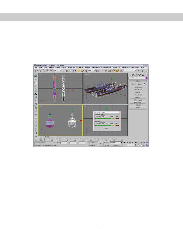
The Polygon Counter utility
For game worlds and models intended for the Web, the polygon count is important when figuring out how quickly a scene will load. For example, a model with 2000 polygons takes roughly twice the amount of time to download and display as a model with 1000 polygons.
To accurately determine the number of polygons in a scene, use the Polygon Counter utility. This simple utility, displayed in Figure 50-1, enables you to set a Budget value for the Selected Objects and for All Objects. It also displays the number of polygons and a graph for each. This utility is located in the Utilities panel, and you can open it by clicking the More button and selecting the Polygon Counter utility.
50C H A P T E R
In This Chapter
Modeling for games
Using channels
Using Vertex Paint
Baking textures

1162 Part XIII Max in Action
Figure 50-1: The Polygon Counter utility helps you understand how complex an object or scene is.
The Level of Detail utility
As a scene is animated, some objects are close to the camera and others are far from it. It doesn’t make much sense to render a complex object that is far from the camera. Using the Level of Detail (LOD) utility, you can have Max render a simpler version of a model when it is farther from the camera and a more complex version when it is close to the camera.
Cross- The MultiRes modifier can also create real-time level of detail updates. You can also create Reference characters in low-res and high-res versions. Both these features are covered in Chapter 36,
“Animating Characters.”
To open the utility, click the More button in the Utility panel and select the Level of Detail utility. A single rollout is loaded into the Utility panel, as shown in Figure 50-2. To use this utility, you need to create several versions of an object and group them together. The Create New Set button lets you pick an object group from the viewports. The objects within the group are individually listed in the rollout pane.
If you select a listed object, you can specify the Thresholds in Pixels or as a percentage of the target image. For each listed item, you can specify a minimum and maximum threshold. The Image Output Size values are used to specify the size of the output image, and the different models that will be used are based on the size of the object in the final image. The Display in Viewports option causes the appropriate LOD model to appear in the viewport.
Figure 50-2: The Level of Detail utility (split into two parts) can specify how objects are viewed based on given thresholds.

Chapter 50 Max and Games 1163
Using the MultiRes Modifier
You can use the MultiRes modifier to create lower resolution versions of a mesh object. This modifier (found in the Modifiers Mesh Editing MultiRes menu) is especially useful for creating real-time updated meshes for the gaming market. After it is applied to a mesh object using the Modifier List in the Modify panel, you can set the desired options in the Generation Parameters section of the MultiRes Parameters rollout and click the Generate button to apply the MultiRes solution to the selected object.
The Vertex Merging option maintains continuity between vertices within the mesh. When enabled, vertices within the Threshold value are welded as the mesh is reduced. The Within Mesh option collapses the boundaries of adjacent elements. The Boundary Metric option looks for boundaries where different materials are applied and tries to maintain these boundaries.
Cross- |
The MultiRes modifier is similar in function to the Optimize modifier, covered in Chapter 14, |
Reference |
“Working with Meshes and Polys.” |
|
The MultiRes modifier includes a single subobject: Vertex. Using this subobject mode, you can select vertices that you don’t want to change. These selected subobject vertices are not altered if the Maintain Base Vertices option is enabled. The Crease Angle value can be used to maintain sharp edges. If any of the options are changed, you can update the solution by clicking the Generation button again.
After it is generated, you can use the Vertex Percent and Vertex Count spinners to control the mesh complexity. The viewport displays the updated mesh as you change its complexity. The rollout displays the number of vertices and faces. The Max Vertex and Max Face fields are the number of vertices and faces in the original mesh; the Face Count is the current number of faces.
Tutorial: Creating a MultiRes battleship
You can use the Optimize modifier to quickly create the lower resolution models, but the MultiRes modifier offers more functionality and enables you to dynamically dial down the resolution to exactly what you want. In this example, we use the MultiRes modifier on a battleship model created by Viewpoint Datalabs.
To create a MultiRes turtle, follow these steps:
1.Open the Kirov battleship.max file from the Chap 50 directory on the CD-ROM. This file contains a battleship model.
2.With the battleship selected, choose Modifiers Mesh Editing MultiRes from the Modifier List to apply the modifier to the battleship model.
3.In the MultiRes Parameters rollout, enable the Vertex Merging option and set the Threshold to 0.05. Also enable the Boundary Metric and Multiple Vertex Normals options, and set the Crease Angle to 75. Then click the Generate button.
4.Create a copy of the battleship by holding down the Shift key and dragging the battleship to the right. In the Clone Options dialog box that appears, select the Copy option and click OK.
1164 Part XIII Max in Action
5.With the cloned battleship selected, set the Vert Percent to 15.
6.Open the Utilities panel, click the More button, and then double-click the Polygon Counter utility. Select the high-resolution version of the battleship on the left, and note the polygon count at 26,176. Then select the battleship on the right, and notice that the number of faces has dropped to 3,817.
Figure 50-3 shows the results of the MultiRes modifier. If you look close, you can see that the battleship on the right isn’t as smooth, but it still looks pretty good.
Figure 50-3: You can use the MultiRes modifier to dynamically dial back the complexity of a mesh.
Using Channels
When 3D models are used in games, the data for the model is stored in channels. The game engine then knows if it wants to change the color of a group of vertices due to an explosion that has happened, it just looks in the preset channel, finds the vertices it needs, changes the color, and then goes on with the game.
Working with channels is a very efficient way to interface with the gaming engine, but a sloppy game developer can introduce a model to the game engine with all sorts of unneeded or exaggerated channels. If this happens, the game engine could ignore the extra channels and get the wrong information, which could cause your hero to march off into battle without a weapon or worst yet, it could crash the system.
Chapter 50 Max and Games 1165
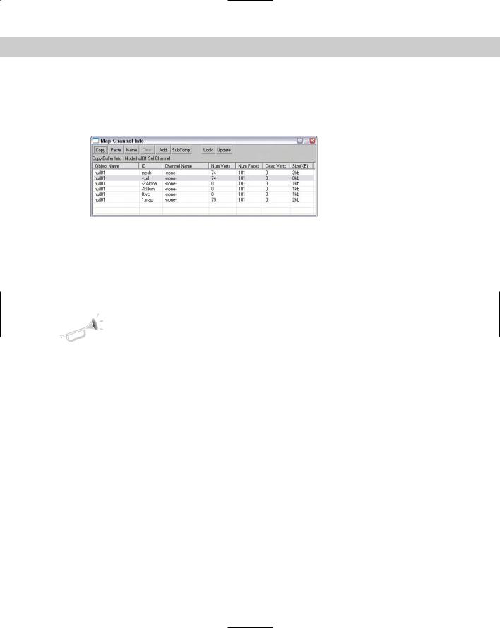
To prevent problems and to streamline the number of channels that are included with game models, Max includes a Map Channel Info editor that you can use to manipulate the various channel data. This editor, shown in Figure 50-4, can be opened using the Tools Channel Info menu command.
Figure 50-4: The Map Channel Info dialog box lets you edit channel data.
Using the Channel Info dialog box
The Map Channel Info dialog box shows lots of information including the Object Name; its ID; its Channel Name; the number of Vertices, Faces, and Dead Vertices; and its Size. With this information, you can quickly determine which channels are taking up the most space and eliminate them.
New |
The Channel Info dialog box is new to 3ds max 6. |
Feature |
|
All objects include some default channels for mesh, which holds the geometry; vsel, which holds the selected vertices; -2:Alpha, which holds the alpha channel information; -1:Illum, which holds illumination values, and channel 0:vc, which holds vertex color information. Objects also include at least one default map channel (even if it is empty). These channels cannot be deleted.
The interface lets you Copy and Paste selected channels. You can give each channel a name with the Name button. Beneath the Copy button, text appears that lists the information currently copied in the Copy Buffer. Channels can be copied only between channels that have the same number of vertices.
The Clear button clears out the selected channels, but you cannot clear a map channel if there is another map channel above it. The Add button adds a new map channel to the object. Objects can hold as many as 99 map channels. The Clear and Add buttons also apply UVW Mapping Clear or UVW Mapping Add modifiers to the Modifier Stack. The Paste command also adds a modifier. These modifiers are convenient because they can easily be removed or reordered in the Stack. If changes have been made in the Modifier Stack, the Update button reflects these changes in the Map Channel Info dialog box.
The SubComp button shows the channel components if they exist. For example, map channels can be broken into X, Y, and Z components, and other channels like Alpha have R, G, and B components. The Lock button holds the current channels even if another object is selected.