

- •Preface
- •About This Book
- •Acknowledgments
- •Contents at a Glance
- •Contents
- •Relaxing at the Beach
- •Dressing the Scene
- •Animating Motion
- •Rendering the Final Animation
- •Summary
- •The Interface Elements
- •Using the Menus
- •Using the Toolbars
- •Using the Viewports
- •Using the Command Panel
- •Using the Lower Interface Bar Controls
- •Interacting with the Interface
- •Getting Help
- •Summary
- •Understanding 3D Space
- •Using the Viewport Navigation Controls
- •Configuring the Viewports
- •Working with Viewport Backgrounds
- •Summary
- •Working with Max Scene Files
- •Setting File Preferences
- •Importing and Exporting
- •Referencing External Objects
- •Using the File Utilities
- •Accessing File Information
- •Summary
- •Customizing Modify and Utility Panel Buttons
- •Working with Custom Interfaces
- •Configuring Paths
- •Selecting System Units
- •Setting Preferences
- •Summary
- •Creating Primitive Objects
- •Exploring the Primitive Object Types
- •Summary
- •Selecting Objects
- •Setting Object Properties
- •Hiding and Freezing Objects
- •Using Layers
- •Summary
- •Cloning Objects
- •Understanding Cloning Options
- •Mirroring Objects
- •Cloning over Time
- •Spacing Cloned Objects
- •Creating Arrays of Objects
- •Summary
- •Working with Groups
- •Building Assemblies
- •Building Links between Objects
- •Displaying Links and Hierarchies
- •Working with Linked Objects
- •Summary
- •Using the Schematic View Window
- •Working with Hierarchies
- •Setting Schematic View Preferences
- •Using List Views
- •Summary
- •Working with the Transformation Tools
- •Using Pivot Points
- •Using the Align Commands
- •Using Grids
- •Using Snap Options
- •Summary
- •Exploring the Modifier Stack
- •Exploring Modifier Types
- •Summary
- •Exploring the Modeling Types
- •Working with Subobjects
- •Modeling Helpers
- •Summary
- •Drawing in 2D
- •Editing Splines
- •Using Spline Modifiers
- •Summary
- •Creating Editable Mesh and Poly Objects
- •Editing Mesh Objects
- •Editing Poly Objects
- •Using Mesh Editing Modifiers
- •Summary
- •Introducing Patch Grids
- •Editing Patches
- •Using Modifiers on Patch Objects
- •Summary
- •Creating NURBS Curves and Surfaces
- •Editing NURBS
- •Working with NURBS
- •Summary
- •Morphing Objects
- •Creating Conform Objects
- •Creating a ShapeMerge Object
- •Creating a Terrain Object
- •Using the Mesher Object
- •Working with BlobMesh Objects
- •Creating a Scatter Object
- •Creating Connect Objects
- •Modeling with Boolean Objects
- •Creating a Loft Object
- •Summary
- •Understanding the Various Particle Systems
- •Creating a Particle System
- •Using the Spray and Snow Particle Systems
- •Using the Super Spray Particle System
- •Using the Blizzard Particle System
- •Using the PArray Particle System
- •Using the PCloud Particle System
- •Using Particle System Maps
- •Controlling Particles with Particle Flow
- •Summary
- •Understanding Material Properties
- •Working with the Material Editor
- •Using the Material/Map Browser
- •Using the Material/Map Navigator
- •Summary
- •Using the Standard Material
- •Using Shading Types
- •Accessing Other Parameters
- •Using External Tools
- •Summary
- •Using Compound Materials
- •Using Raytrace Materials
- •Using the Matte/Shadow Material
- •Using the DirectX 9 Shader
- •Applying Multiple Materials
- •Material Modifiers
- •Summary
- •Understanding Maps
- •Understanding Material Map Types
- •Using the Maps Rollout
- •Using the Map Path Utility
- •Using Map Instances
- •Summary
- •Mapping Modifiers
- •Using the Unwrap UVW modifier
- •Summary
- •Working with Cameras
- •Setting Camera Parameters
- •Summary
- •Using the Camera Tracker Utility
- •Summary
- •Using Multi-Pass Cameras
- •Creating Multi-Pass Camera Effects
- •Summary
- •Understanding the Basics of Lighting
- •Getting to Know the Light Types
- •Creating and Positioning Light Objects
- •Viewing a Scene from a Light
- •Altering Light Parameters
- •Working with Photometric Lights
- •Using the Sunlight and Daylight Systems
- •Using Volume Lights
- •Summary
- •Selecting Advanced Lighting
- •Using Local Advanced Lighting Settings
- •Tutorial: Excluding objects from light tracing
- •Summary
- •Understanding Radiosity
- •Using Local and Global Advanced Lighting Settings
- •Working with Advanced Lighting Materials
- •Using Lighting Analysis
- •Summary
- •Using the Time Controls
- •Working with Keys
- •Using the Track Bar
- •Viewing and Editing Key Values
- •Using the Motion Panel
- •Using Ghosting
- •Animating Objects
- •Working with Previews
- •Wiring Parameters
- •Animation Modifiers
- •Summary
- •Understanding Controller Types
- •Assigning Controllers
- •Setting Default Controllers
- •Examining the Various Controllers
- •Summary
- •Working with Expressions in Spinners
- •Understanding the Expression Controller Interface
- •Understanding Expression Elements
- •Using Expression Controllers
- •Summary
- •Learning the Track View Interface
- •Working with Keys
- •Editing Time
- •Editing Curves
- •Filtering Tracks
- •Working with Controllers
- •Synchronizing to a Sound Track
- •Summary
- •Understanding Your Character
- •Building Bodies
- •Summary
- •Building a Bones System
- •Using the Bone Tools
- •Using the Skin Modifier
- •Summary
- •Creating Characters
- •Working with Characters
- •Using Character Animation Techniques
- •Summary
- •Forward versus Inverse Kinematics
- •Creating an Inverse Kinematics System
- •Using the Various Inverse Kinematics Methods
- •Summary
- •Creating and Binding Space Warps
- •Understanding Space Warp Types
- •Combining Particle Systems with Space Warps
- •Summary
- •Understanding Dynamics
- •Using Dynamic Objects
- •Defining Dynamic Material Properties
- •Using Dynamic Space Warps
- •Using the Dynamics Utility
- •Using the Flex Modifier
- •Summary
- •Using reactor
- •Using reactor Collections
- •Creating reactor Objects
- •Calculating and Previewing a Simulation
- •Constraining Objects
- •reactor Troubleshooting
- •Summary
- •Understanding the Max Renderers
- •Previewing with ActiveShade
- •Render Parameters
- •Rendering Preferences
- •Creating VUE Files
- •Using the Rendered Frame Window
- •Using the RAM Player
- •Reviewing the Render Types
- •Using Command-Line Rendering
- •Creating Panoramic Images
- •Getting Printer Help
- •Creating an Environment
- •Summary
- •Creating Atmospheric Effects
- •Using the Fire Effect
- •Using the Fog Effect
- •Summary
- •Using Render Elements
- •Adding Render Effects
- •Creating Lens Effects
- •Using Other Render Effects
- •Summary
- •Using Raytrace Materials
- •Using a Raytrace Map
- •Enabling mental ray
- •Summary
- •Understanding Network Rendering
- •Network Requirements
- •Setting up a Network Rendering System
- •Starting the Network Rendering System
- •Configuring the Network Manager and Servers
- •Logging Errors
- •Using the Monitor
- •Setting up Batch Rendering
- •Summary
- •Compositing with Photoshop
- •Video Editing with Premiere
- •Video Compositing with After Effects
- •Introducing Combustion
- •Using Other Compositing Solutions
- •Summary
- •Completing Post-Production with the Video Post Interface
- •Working with Sequences
- •Adding and Editing Events
- •Working with Ranges
- •Working with Lens Effects Filters
- •Summary
- •What Is MAXScript?
- •MAXScript Tools
- •Setting MAXScript Preferences
- •Types of Scripts
- •Writing Your Own MAXScripts
- •Learning the Visual MAXScript Editor Interface
- •Laying Out a Rollout
- •Summary
- •Working with Plug-Ins
- •Locating Plug-Ins
- •Summary
- •Low-Res Modeling
- •Using Channels
- •Using Vertex Colors
- •Rendering to a Texture
- •Summary
- •Max and Architecture
- •Using AEC Objects
- •Using Architectural materials
- •Summary
- •Tutorial: Creating Icy Geometry with BlobMesh
- •Tutorial: Using Caustic Photons to Create a Disco Ball
- •Summary
- •mental ray Rendering System
- •Particle Flow
- •reactor 2.0
- •Schematic View
- •BlobMesh
- •Spline and Patch Features
- •Import and Export
- •Shell Modifier
- •Vertex Paint and Channel Info
- •Architectural Primitives and Materials
- •Minor Improvements
- •Choosing an Operating System
- •Hardware Requirements
- •Installing 3ds max 6
- •Authorizing the Software
- •Setting the Display Driver
- •Updating Max
- •Moving Max to Another Computer
- •Using Keyboard Shortcuts
- •Using the Hotkey Map
- •Main Interface Shortcuts
- •Dialog Box Shortcuts
- •Miscellaneous Shortcuts
- •System Requirements
- •Using the CDs with Windows
- •What’s on the CDs
- •Troubleshooting
- •Index

Chapter 20 Creating Simple Materials 583
Figure 20-15: A fishing net completed easily with the net texture applied as an Opacity map
Summary
This chapter presented the Standard material and gave you a chance to create some simple original materials.
In this chapter, you
Learned about various material types
Discovered and learned to use the various material parameters
Discovered the basics of using standard materials
Learned how to use the various shaders
Explored the other Material rollouts
Learned how to create materials using external tools such as Photoshop and a digital camera.
This chapter should have been enough to whet your appetite for materials, and yet it really covered only one material — the Standard material. Many other materials are available, and we dive into those in the next chapter.
|
|
|


Creating Advanced
Multi-Layer
Materials
Now that you’ve learned to create materials using the Standard material type, you get a chance to see the variety of materials
that you can create in Max. You can select all the various Max materials from the Material/Map Browser. Open this browser automatically by clicking the Material Type button beneath the sample slots.
Although these are called Compound materials, they are really just collections of materials that work together as one. Just like a mesh object can include multiple elements, materials also can be made up of several materials.
Using Compound Materials
Compound materials combine several different materials into one. You select a compound object type by clicking the Type button in the Material Editor and then selecting the material type from the Material/ Map Browser. The Type button is the button to the right of the material name. It lists the current material on the button, such as Standard, which is the default material. Most of the entries in the Material/Map Browser are compound objects.
Whenever compound materials are selected, the Replace Material dialog box appears, asking whether you want to discard the current material or make the old material a submaterial. This feature enables you to change a normal material into a compound material while retaining the current material.
Compound materials usually include several different levels. For example, a Top/Bottom material includes a separate material for the top and the bottom. Each of these submaterials can then include another Top/Bottom material, and so on. The Material/Map Navigator dialog box (accessed by clicking the Material/Map Navigator button) displays the material as a hierarchical list. This list lets you easily choose the level you want to work with.
21C H A P T E R
In This Chapter
Creating and using compound materials
Using raytrace materials
Using matte/shadow materials
Using Ink ‘n’ Paint materials
Using material IDs to apply multiple materials
Working with material modifiers such as MaterialByElement
586 Part IV Materials and Maps
Cross- |
Chapter 19, “Exploring the Material Editor,” covers the Material/Map Navigator in more detail. |
Reference |
|
Each compound material includes a customized rollout for specifying the submaterials associated with the compound material.
Cross-
Reference
Some of the material types work closely with specific objects and other Max features. These materials are covered in their respective chapters. For example, the Advanced Lighting Override material is presented in Chapter 28, “Advanced Lighting and Light Tracing,” and the Architectural material is presented in Chapter 51, “Max and Visualization.”
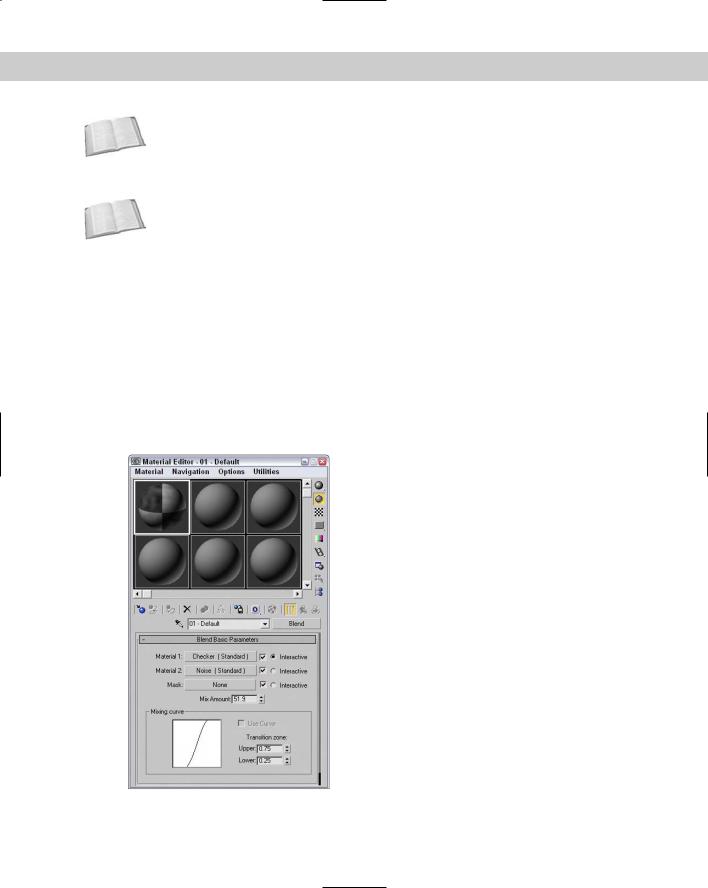
Blend
The Blend material blends two separate materials on a surface. The Blend Basic Parameters rollout, shown in Figure 21-1, includes buttons for loading the two submaterials. The check boxes to the right of these buttons enable or disable each submaterial. The Interactive option enables you to select one of the submaterials to be viewed in the viewports.
The Mask button (which appears below the two submaterial buttons) lets you load a map to specify how the submaterials are mixed. White areas on the map are well blended, and black areas don’t blend at all. As an alternative to a mask, the Mix Amount determines how much of each submaterial to display. A value of 0 displays only Material 1, and a value of 100 displays only Material 2.
Figure 21-1: The Blend material can include a mask to define the areas that are blended.
Chapter 21 Creating Advanced Multi-Layer Materials |
587 |
The Mixing Curve defines the transition between edges of the two materials. The Upper and Lower spinners help you control the curve.
Composite
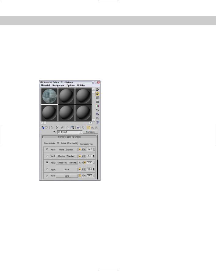
The Composite material mixes up to ten different materials by adding, subtracting, or mixing the opacity. The Composite Basic Parameters rollout, shown in Figure 21-2, includes buttons for the base material and ten additional materials that can be composited on top of the base material. The materials are applied from top to bottom.
Figure 21-2: Composite materials are applied from top to bottom with the
last layer being placed on top of the rest.
You enable or disable each material using the check box to its left. The buttons labeled with the letters A, S, and M specify the opacity type: Additive, Subtractive, or Mix. The Additive option brightens the material by adding the background colors to the current material. The Subtractive option has the opposite effect and subtracts the background colors from the current material. The Mix option blends the materials based on their Amount values.
To the right of the A, S, and M buttons is the Mix amount. This value can range from 0 to 200. At 0, none of the materials below it will be visible. At 100, full compositing occurs. Values greater than 100 cause transparent regions to become more opaque.

588 Part IV Materials and Maps
Cross- You can learn more about compositing in Chapter 46, “Using External Compositing Tools,” Reference and compositing with the Video Post interface in Chapter 47, “Using the Video Post
Interface.”
Double Sided
The Double Sided material specifies different materials for the front and back of object faces. You also have an option to make the material translucent. This material is for objects that have holes in their surface. Typically, objects with surface holes do not appear correctly because only the surfaces with normals pointing outward are visible. Applying the Double Sided material shows the interior and exterior of such an object.
The Double Sided Basic Parameters rollout includes two buttons, one for the Facing material and one for the Back material. The Translucency value sets how much of one material shows through the other.
Shellac
The Shellac material is added on top of the Base material. The Shellac Basic Parameters rollout includes only two buttons for each material, along with a Color Blend value. The Blend value has no upper limit.
Multi/Sub-Object
You can use the Multi/Sub-Object material to assign several different materials to a single object via the material IDs. You can use the Mesh Select modifier to select each subobject area to receive the different materials.
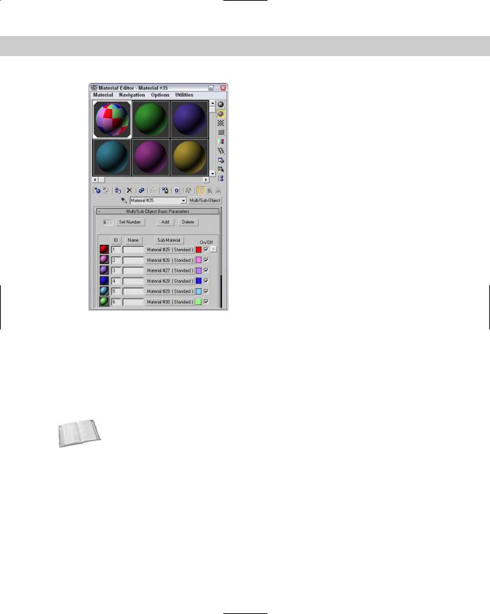
At the top of the Multi/Sub-Object Basic Parameters rollout, shown in Figure 21-3, is a Set Number button that lets you select the number of subobject materials to include. This number is displayed in a text field to the left of the button. Each submaterial is displayed as a separate area on the sample object in the sample slots. Using the Add and Delete buttons, you can selectively add or delete submaterials from the list.
Each submaterial includes a sample preview of the submaterial and an index number listed to the left, a Name field where you can type the name of the submaterial, a button for selecting the material, a color swatch for creating solid color materials, and a check box for enabling or disabling the submaterial. You can sort the submaterials by clicking the ID, Name, or SubMaterial buttons at the top of each column.
After you apply a Multi/Sub-Object material to an object, use the Mesh Select modifier to make a subobject selection. In the Material section for this subobject selection, choose a material ID to associate with a submaterial ID or select the material by name from the dropdown list.
Chapter 21 Creating Advanced Multi-Layer Materials |
589 |
Figure 21-3: The Multi/Sub-Object material defines materials according to material IDs.
Tutorial: Creating a patchwork quilt
When I think of patches, I think of a 3D Max object type, but for many people, “patches” instead bring to mind small scraps of cloth used to make a quilt. Because they share the same name, maybe we can use Max patches to create a quilt. We can then use the Multi/Sub-Object material to appropriately color the various patches.
Cross- You can learn more about modeling with patches in Chapter 15, “Creating and Editing
Reference Patches.”
To create a quilt using patches, follow these steps:
1.Open the Patch quilt.max file from the Chap 21 directory on the CD-ROM.
This file contains a quilt made of patch objects that have been combined into one object.
590 Part IV Materials and Maps
2.Open the Material Editor by choosing Rendering Material Editor (or press M), and click the first sample slot. Then click the Type button. The Material/Map Browser opens. In the list of materials, locate and double-click the Multi/Sub-Object material (or select it and press the Ok button). In the dialog box that appears, select Discard old material and click OK.
The Multi/Sub-Object material loads into the selected sample slot, and the Multi/SubObject Basic Parameters rollout displays in the Material Editor.
3.In the Multi/Sub-Object Basic Parameters rollout, click the color swatches to the right of the Material button to open the Color Selector. Select different colors for each of the first ten material ID slots.
4.Drag the Multi/Sub-Object material from its sample slot in the Material Editor, and drop it onto the patch object. Close the Material/Map Browser and the Material Editor.
5.In the Modify panel, select the Patch subobject and scroll to the bottom of the Modify panel to the Surface Properties rollout.
6.Assign each patch a separate material ID by clicking a patch and changing the ID number in the rollout field.
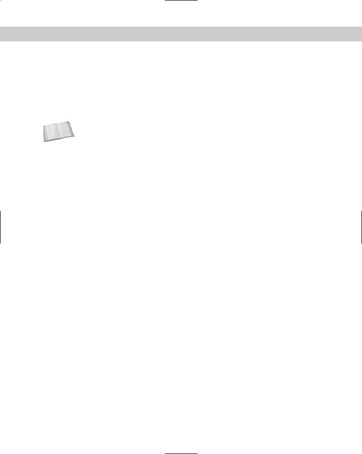
Figure 21-4 shows the finished quilt. Because it’s a patch, you can drape it over objects easily.
Figure 21-4: A quilt composed of patches and colored using the Multi/Sub-Object material
Chapter 21 Creating Advanced Multi-Layer Materials |
591 |
Morpher
The Morpher material type works with the Morpher modifier to change materials as an object morphs. For example, you can associate a blushing effect with light red applied to the cheeks of a facial expression to show embarrassment. You can use this material only on an object that has the Morpher modifier in its Stack. The Morpher modifier includes a button called Assign New Material in the Global Parameters rollout for loading the Material Editor with the Morpher material type.
Cross- |
Discover more about the Morpher modifier in Chapter 30, “Animation Basics.” |
Reference |
|
For the Morpher material, the Choose Morph Object button in the Morpher Basic Parameters rollout lets you pick a morpher object in the viewports and then opens a dialog box that is used to bind the Morpher material to an object with the Morpher modifier applied. The Refresh button updates all the channels. The base material is the material used before any channel effects are used.
The Morpher material includes 100 channels that correlate to the channels included in the Morpher modifier. Each channel can be turned on and off. At the bottom of the parameters rollout are three Mixing Calculation options that can be used to determine how often the blending is calculated. The Always setting can consume lots of memory and can slow down the system. Other options are When Rendering and Never Calculate.
Shell
The Shell material consists of an original material and a baked material. For each of these materials, you can specify which appear in the Viewport and which are rendered.
Top/Bottom
The Top/Bottom material assigns different materials to the top and bottom of an object. The Top and Bottom areas are determined by the direction in which the face normals point. These normals can be according to the World or Local coordinate system. You can also blend the two materials.
The Top/Bottom Basic Parameters rollout includes two buttons for loading the Top and Bottom materials. You can use the Swap button to switch the two materials. Using World coordinates enables you to rotate the object without changing the material positions. Local coordinates tie the material to the object.
The Blend value can range from 0 to 100, with 0 being a hard edge and 100 being a smooth transition. The Position value sets the location where the two materials meet. A value of 0 represents the bottom of the object and displays only the top material. A value of 100 represents the top of the object, and only the Bottom material is displayed.
Tutorial: Surfing the waves
There’s nothing like hitting the surf early in the morning, unless you consider hitting the virtual surf early in the morning. As an example of a compound material, we apply the Top/Bottom material to a surfboard.