

- •Preface
- •About This Book
- •Acknowledgments
- •Contents at a Glance
- •Contents
- •Relaxing at the Beach
- •Dressing the Scene
- •Animating Motion
- •Rendering the Final Animation
- •Summary
- •The Interface Elements
- •Using the Menus
- •Using the Toolbars
- •Using the Viewports
- •Using the Command Panel
- •Using the Lower Interface Bar Controls
- •Interacting with the Interface
- •Getting Help
- •Summary
- •Understanding 3D Space
- •Using the Viewport Navigation Controls
- •Configuring the Viewports
- •Working with Viewport Backgrounds
- •Summary
- •Working with Max Scene Files
- •Setting File Preferences
- •Importing and Exporting
- •Referencing External Objects
- •Using the File Utilities
- •Accessing File Information
- •Summary
- •Customizing Modify and Utility Panel Buttons
- •Working with Custom Interfaces
- •Configuring Paths
- •Selecting System Units
- •Setting Preferences
- •Summary
- •Creating Primitive Objects
- •Exploring the Primitive Object Types
- •Summary
- •Selecting Objects
- •Setting Object Properties
- •Hiding and Freezing Objects
- •Using Layers
- •Summary
- •Cloning Objects
- •Understanding Cloning Options
- •Mirroring Objects
- •Cloning over Time
- •Spacing Cloned Objects
- •Creating Arrays of Objects
- •Summary
- •Working with Groups
- •Building Assemblies
- •Building Links between Objects
- •Displaying Links and Hierarchies
- •Working with Linked Objects
- •Summary
- •Using the Schematic View Window
- •Working with Hierarchies
- •Setting Schematic View Preferences
- •Using List Views
- •Summary
- •Working with the Transformation Tools
- •Using Pivot Points
- •Using the Align Commands
- •Using Grids
- •Using Snap Options
- •Summary
- •Exploring the Modifier Stack
- •Exploring Modifier Types
- •Summary
- •Exploring the Modeling Types
- •Working with Subobjects
- •Modeling Helpers
- •Summary
- •Drawing in 2D
- •Editing Splines
- •Using Spline Modifiers
- •Summary
- •Creating Editable Mesh and Poly Objects
- •Editing Mesh Objects
- •Editing Poly Objects
- •Using Mesh Editing Modifiers
- •Summary
- •Introducing Patch Grids
- •Editing Patches
- •Using Modifiers on Patch Objects
- •Summary
- •Creating NURBS Curves and Surfaces
- •Editing NURBS
- •Working with NURBS
- •Summary
- •Morphing Objects
- •Creating Conform Objects
- •Creating a ShapeMerge Object
- •Creating a Terrain Object
- •Using the Mesher Object
- •Working with BlobMesh Objects
- •Creating a Scatter Object
- •Creating Connect Objects
- •Modeling with Boolean Objects
- •Creating a Loft Object
- •Summary
- •Understanding the Various Particle Systems
- •Creating a Particle System
- •Using the Spray and Snow Particle Systems
- •Using the Super Spray Particle System
- •Using the Blizzard Particle System
- •Using the PArray Particle System
- •Using the PCloud Particle System
- •Using Particle System Maps
- •Controlling Particles with Particle Flow
- •Summary
- •Understanding Material Properties
- •Working with the Material Editor
- •Using the Material/Map Browser
- •Using the Material/Map Navigator
- •Summary
- •Using the Standard Material
- •Using Shading Types
- •Accessing Other Parameters
- •Using External Tools
- •Summary
- •Using Compound Materials
- •Using Raytrace Materials
- •Using the Matte/Shadow Material
- •Using the DirectX 9 Shader
- •Applying Multiple Materials
- •Material Modifiers
- •Summary
- •Understanding Maps
- •Understanding Material Map Types
- •Using the Maps Rollout
- •Using the Map Path Utility
- •Using Map Instances
- •Summary
- •Mapping Modifiers
- •Using the Unwrap UVW modifier
- •Summary
- •Working with Cameras
- •Setting Camera Parameters
- •Summary
- •Using the Camera Tracker Utility
- •Summary
- •Using Multi-Pass Cameras
- •Creating Multi-Pass Camera Effects
- •Summary
- •Understanding the Basics of Lighting
- •Getting to Know the Light Types
- •Creating and Positioning Light Objects
- •Viewing a Scene from a Light
- •Altering Light Parameters
- •Working with Photometric Lights
- •Using the Sunlight and Daylight Systems
- •Using Volume Lights
- •Summary
- •Selecting Advanced Lighting
- •Using Local Advanced Lighting Settings
- •Tutorial: Excluding objects from light tracing
- •Summary
- •Understanding Radiosity
- •Using Local and Global Advanced Lighting Settings
- •Working with Advanced Lighting Materials
- •Using Lighting Analysis
- •Summary
- •Using the Time Controls
- •Working with Keys
- •Using the Track Bar
- •Viewing and Editing Key Values
- •Using the Motion Panel
- •Using Ghosting
- •Animating Objects
- •Working with Previews
- •Wiring Parameters
- •Animation Modifiers
- •Summary
- •Understanding Controller Types
- •Assigning Controllers
- •Setting Default Controllers
- •Examining the Various Controllers
- •Summary
- •Working with Expressions in Spinners
- •Understanding the Expression Controller Interface
- •Understanding Expression Elements
- •Using Expression Controllers
- •Summary
- •Learning the Track View Interface
- •Working with Keys
- •Editing Time
- •Editing Curves
- •Filtering Tracks
- •Working with Controllers
- •Synchronizing to a Sound Track
- •Summary
- •Understanding Your Character
- •Building Bodies
- •Summary
- •Building a Bones System
- •Using the Bone Tools
- •Using the Skin Modifier
- •Summary
- •Creating Characters
- •Working with Characters
- •Using Character Animation Techniques
- •Summary
- •Forward versus Inverse Kinematics
- •Creating an Inverse Kinematics System
- •Using the Various Inverse Kinematics Methods
- •Summary
- •Creating and Binding Space Warps
- •Understanding Space Warp Types
- •Combining Particle Systems with Space Warps
- •Summary
- •Understanding Dynamics
- •Using Dynamic Objects
- •Defining Dynamic Material Properties
- •Using Dynamic Space Warps
- •Using the Dynamics Utility
- •Using the Flex Modifier
- •Summary
- •Using reactor
- •Using reactor Collections
- •Creating reactor Objects
- •Calculating and Previewing a Simulation
- •Constraining Objects
- •reactor Troubleshooting
- •Summary
- •Understanding the Max Renderers
- •Previewing with ActiveShade
- •Render Parameters
- •Rendering Preferences
- •Creating VUE Files
- •Using the Rendered Frame Window
- •Using the RAM Player
- •Reviewing the Render Types
- •Using Command-Line Rendering
- •Creating Panoramic Images
- •Getting Printer Help
- •Creating an Environment
- •Summary
- •Creating Atmospheric Effects
- •Using the Fire Effect
- •Using the Fog Effect
- •Summary
- •Using Render Elements
- •Adding Render Effects
- •Creating Lens Effects
- •Using Other Render Effects
- •Summary
- •Using Raytrace Materials
- •Using a Raytrace Map
- •Enabling mental ray
- •Summary
- •Understanding Network Rendering
- •Network Requirements
- •Setting up a Network Rendering System
- •Starting the Network Rendering System
- •Configuring the Network Manager and Servers
- •Logging Errors
- •Using the Monitor
- •Setting up Batch Rendering
- •Summary
- •Compositing with Photoshop
- •Video Editing with Premiere
- •Video Compositing with After Effects
- •Introducing Combustion
- •Using Other Compositing Solutions
- •Summary
- •Completing Post-Production with the Video Post Interface
- •Working with Sequences
- •Adding and Editing Events
- •Working with Ranges
- •Working with Lens Effects Filters
- •Summary
- •What Is MAXScript?
- •MAXScript Tools
- •Setting MAXScript Preferences
- •Types of Scripts
- •Writing Your Own MAXScripts
- •Learning the Visual MAXScript Editor Interface
- •Laying Out a Rollout
- •Summary
- •Working with Plug-Ins
- •Locating Plug-Ins
- •Summary
- •Low-Res Modeling
- •Using Channels
- •Using Vertex Colors
- •Rendering to a Texture
- •Summary
- •Max and Architecture
- •Using AEC Objects
- •Using Architectural materials
- •Summary
- •Tutorial: Creating Icy Geometry with BlobMesh
- •Tutorial: Using Caustic Photons to Create a Disco Ball
- •Summary
- •mental ray Rendering System
- •Particle Flow
- •reactor 2.0
- •Schematic View
- •BlobMesh
- •Spline and Patch Features
- •Import and Export
- •Shell Modifier
- •Vertex Paint and Channel Info
- •Architectural Primitives and Materials
- •Minor Improvements
- •Choosing an Operating System
- •Hardware Requirements
- •Installing 3ds max 6
- •Authorizing the Software
- •Setting the Display Driver
- •Updating Max
- •Moving Max to Another Computer
- •Using Keyboard Shortcuts
- •Using the Hotkey Map
- •Main Interface Shortcuts
- •Dialog Box Shortcuts
- •Miscellaneous Shortcuts
- •System Requirements
- •Using the CDs with Windows
- •What’s on the CDs
- •Troubleshooting
- •Index
Chapter 17 Building Compound Objects 477
Creating Conform Objects
Conform compound objects mold one object over the surface of another. This compound object is useful for adding geometric details to objects, such as stitches to a baseball or a quilt.
The object that is modified is called the Wrapper object. The other object is the Wrap-To object. These objects need to be either mesh objects or objects that you can convert to mesh objects.
Cross- |
Another way to mold one object over the surface of another is with the Conform Space |
Reference |
Warp. Find out more about this Space Warp in Chapter 38, “Using Space Warps.” |
|
To create a Conform object, select an object to be the Wrapper object and select Create Compound Conform. To select the Wrap-To object, click the Pick Wrap-To Object button in the Pick Wrap-To Object rollout and choose one of the options below the button (Reference, Move, Copy, or Instance).
Caution |
Shapes and splines cannot be used as either the Wrapper or Wrap-To objects, even if they are |
|
renderable. |
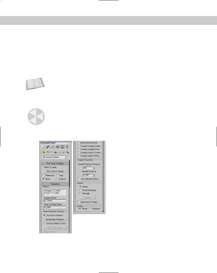
In the Parameters rollout, shown in Figure 17-3, the Objects section lists both the Wrapper and Wrap-To objects. Name fields are also available for changing the names of both objects.
Figure 17-3: The Parameters rollout of the Conform object lets you define how the object is wrapped.

478 Part III Modeling
The Wrapper Parameters section includes two adjustable values: Default Projection Distance, which is the distance that the Wrapper moves if it doesn’t intersect with the Wrap-To object, and Standoff Distance, which is the distance between the Wrapper and the Wrap-To object.
The Use Selected Vertices option causes only the selected vertices passed up the Stack to be moved.
Setting a vertex projection direction
The Parameters rollout also includes controls for specifying the Vertex Projection Direction settings. You can select to project the vertices based on the current active viewport with the Use Active Viewport option. If the view changes, you can use the Recalculate Projection button to compute the new projection direction.
You can also use the local Z axis of any object in the scene as the projection direction. The Pick Z-Axis Object button lets you select the object to use. After you have selected it, rotating this object can alter the projection direction. The name of the object is displayed below the Pick Z-Axis Object button.
Other projection options include Along Vertex Normals, Towards Wrapper Center, Towards Wrapper Pivot, Towards Wrap-To Center, and Towards Wrap-To Pivot. The Along Vertex Normals option sets the projection direction opposite the Wrapper’s normals. The other options set the direction toward the center or pivot of the Wrapper or Wrap-To objects.
Tutorial: Placing a facial scar
As an example of the Conform object, let’s add a gruesome scar to the face of our character. Using the Conform compound object, details like this scar can be a mesh object and still perfectly match the contour of the face object.
To create a facial scar using the Conform object, follow these steps:
1.Open the Facial scar.max file from the Chap 17 directory on the CD-ROM.
This file includes a face mesh with a mesh scar placed to its side. The face mesh was created by Viewpoint Datalabs.
2.Click the Select and Move button on the main toolbar, and select and move the scar to position it in front of the face mesh in the Front viewport.
3.With the scar selected, choose the Create Compound Conform menu command.
4.Click the Pick Wrap-To Object button, and click the face mesh. Select the Move option.
5.Under the Parameters rollout, select the Use Active Viewport option and make sure that the Front viewport is active. In the Wrapper Parameters section, set the Standoff Distance value to 1.0.
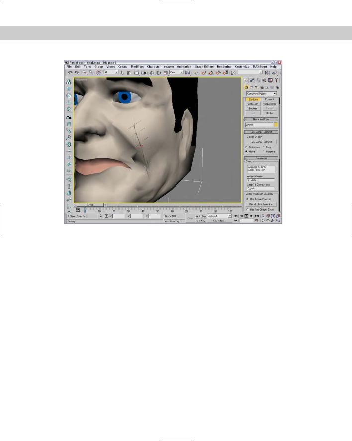
Figure 17-4 shows a close-up of our surgery in the maximized Perspective view.
Chapter 17 Building Compound Objects 479
Figure 17-4: A patch grid being conformed to the front of a face object
Creating a ShapeMerge Object
The ShapeMerge compound object enables you to use a spline shape as a cookie cutter to extract a portion of a mesh object. This button is enabled only if a mesh object and a spline exist in the scene. To use this object, select a mesh object and click the Pick Shape button in the Pick Operand rollout, and then select a spline shape. The shape can be a Reference, Move, Instance, or Copy.
The spline shape is always projected toward its negative Z axis. By rotating and positioning the spline before selecting it, you can apply it to different sides of an object. You can apply multiple shapes to the same mesh object.
The Parameters rollout, shown in Figure 17-5, displays each mesh and shape object in a list. You can also rename either object using the Name field. The Extract Operand button lets you separate either object as an Instance or a Copy.
480 Part III Modeling
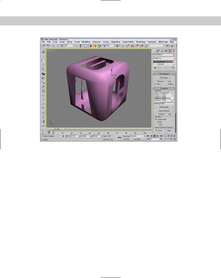
Figure 17-5: Use the Parameters rollout for the ShapeMerge compound object to cut or merge a shape.
Cookie Cutter and Merge options
The Operations group includes options for cutting the mesh, including Cookie Cutter and Merge. The Cookie Cutter option cuts the shape out of the mesh surface, and the Merge option combines the spline with the mesh. You can also Invert the operation to remove the inside or outside of the selected area.
Like the Boolean Subtraction operations, the Cookie Cutter option can remove sections of the mesh, but it uses the area defined by a spline instead of a volume defined by a mesh object. The Merge option is useful for marking an area for selection. Figure 17-6 shows a ShapeMerge object with the Cookie Cutter option selected.
Note You can use the Merge option to create a precise face object that can be used with the Connect object.
The Output Sub-Mesh Selection option lets you pass the selection up the Stack for additional modifiers. Options include None, Face, Edge, and Vertex.
Note To see the backsides of the faces, right-click the object, select Properties from the pop-up menu, and disable the Backface Cull option.
Tutorial: Using the ShapeMerge compound object
When outlined text is imported into Max, it typically contains letters that have shapes within shapes. For example, the letter p, when outlined, includes the outline of the letter p and a circle shape to denote the interior section of the letter. When outline text like this is converted to a mesh object, both the letter outline and its interior section are covered, making the text illegible. You can use the ShapeMerge compound object to remedy this tricky situation.
Chapter 17 Building Compound Objects 481
Figure 17-6: A ShapeMerge object using the Cookie Cutter option
In Chapter 3, “Working with Files and XRefs,” you encounter an example where the logo for the fictional Bugs Head Software company was imported from Illustrator. Before this logo can be extruded, you need to do some work involving the ShapeMerge object.
To use the ShapeMerge object to remove the center area from an extrusion, follow these steps:
1.Open the Bugs Head Software logo.max file from the Chap 17 directory on the CD-ROM.
This file is slightly different from the file found in Chapter 3. For example, the bug’s mouth has been made into a closed spline.
2.Click away from the objects to deselect all the objects, and select (while holding down the Ctrl key) the two interior splines of the letter B that make up the bug’s left eye. Open the Display Floater by choosing Tools Display Floater, and click the Selected button under the Hide column to hide the interior portions of this letter.
3.Select the bug’s head shape again. Then select the Create Compound ShapeMerge menu command.
4.Set the Operation to Cookie Cutter, and click the Pick Shape button in the Pick Operand rollout with the Copy option. Select the mouth and the letters used for the eyes and nose. Click the Select Object button on the main toolbar to exit pick mode and to deselect the bug’s head.