

Chapter 6 Selecting Objects and Setting Object Properties |
199 |
A third interface that you can use to select objects is the Schematic View, which is opened using the Graph Editors New Schematic View menu command. It offers a hierarchical look at your scene and displays all links and relationships between objects. Each object in the Schematic View is displayed as a rectangular node.
To select an object in the viewport, find its rectangular representation in the Schematic View and simply double-click it. To select multiple objects in the Schematic View, you need to enable Sync Selection mode with the Select Sync Selection command in the Schematic View menu and then drag an outline over all the rectangular nodes that you want to select.
The Schematic View also includes the Select by Name text field, just like the Curve Editor, for selecting an object by typing its name.
Cross- The Material Editor is covered in detail in Chapter 19, “Exploring the Material Editor,” the Reference Track View is covered in Chapter 33, “Working with the Track View,” and the Schematic View
interface is covered in Chapter 9, “Working with the Schematic View.”
Setting Object Properties
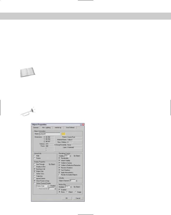
After you select an object or multiple objects, you can view their object properties by choosing Edit Object Properties. Alternatively, you can right-click the object and select Properties from the pop-up menu. Figure 6-8 shows the Object Properties dialog box. This dialog box includes four panels — General, Advanced Lighting, mental ray, and User Defined.
New |
The Object Properties dialog box has changed slightly. Along with rearranging the sections, |
Feature |
the Vertex Channel Display and Map Channel options are new. |
|
Figure 6-8: The Object Properties dialog box displays valuable information about a selected object.
200 Part II Working with Objects
Viewing object information
For a single object, the General panel of the Object Properties dialog box lists details about the object in the Object Information section. These details include the object’s name; color; extent distances from the origin along the X, Y and Z axes; number of vertices and faces; who the object’s parent is; the object’s Material Name; the number of children attached to the object; the object’s group name if it’s part of a group; and the layer on which the object can be found. All this information (except for its name and color) is for display only and cannot be changed.
Note The two fields under the Vertices and Faces are used only when the properties for a Shape are being displayed. These fields show the number of Shape Vertices and Shape Curves.
If the properties for multiple objects are to be displayed, the Object Properties dialog box places the text “Multiple Selected” in the Name field. The properties that are in common between all these objects are displayed. With multiple objects selected, you can set their display and rendering properties all at once.
The Object Properties dialog box can be displayed for all geometric objects and shapes, as well as for lights, cameras, helpers, and Space Warps. Not all properties are available for all objects.
Cross- |
The Hide and Freeze options included in the Interactivity section are covered later in the |
Reference |
chapter in the “Hiding and Freezing Objects” section. |
|
Setting display properties
Display properties don’t affect how an object is rendered, only how it is displayed in the viewports. In this section, along with the Rendering Control and Motion Blur sections, are three By Object/By Layer toggle buttons. If the By Object button is displayed, then options can be set for the selected object, but if the By Layer option is enabled, then all options become disabled and the object gets its display properties from the layer settings found in the Layer Manager.
Note |
You can also find and set the same Display Properties that are listed in the Object Properties |
|
dialog box in the Display Properties rollout of the Display panel in the Command Panel and |
|
in the Display Floater. |
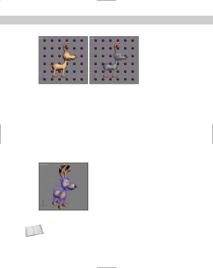
The See-Through option causes shaded objects to appear transparent. This option is similar to the Visibility setting in the Rendering Control section, except that it doesn’t affect the rendered image. It is only for displaying objects in the viewports. This option really doesn’t help in wireframe viewports. Figure 6-9 shows a deer model with spheres behind it with and without this option selected.
Many of these display properties can speed up or slow down the viewport refresh rates. For example, Display as Box increases the viewport update rate dramatically for complex scenes, but at the expense of any detail. This setting can be useful to see how the objects generally fit in comparison to one another. This option can also be accessed from the Viewport Configuration dialog box or from the Viewport name right-click pop-up menu, but the Object Properties dialog box lets you set this option for a single object instead of for the entire viewport.
Chapter 6 Selecting Objects and Setting Object Properties |
201 |
Figure 6-9: The See-Through display property can make objects transparent in the viewports.
The Backface Cull option causes the faces on the backside of the object to not be displayed when turned on. Max considers the direction that each normal is pointing and doesn’t display a face if its normal points away from the view. A normal is a vector that extends perpendicular to the face and is used to determine the orientation of individual faces. This option produces the same result of the Force 2-Sided option in the Viewport Configuration dialog box, except that it can be applied to a single object and not the entire viewport. This display option works only in wireframe viewports.
The Edges Only option displays only the edges of each face when the viewport is set to Wireframe mode. When Edges Only is not selected, a dashed line indicates polygon faces.
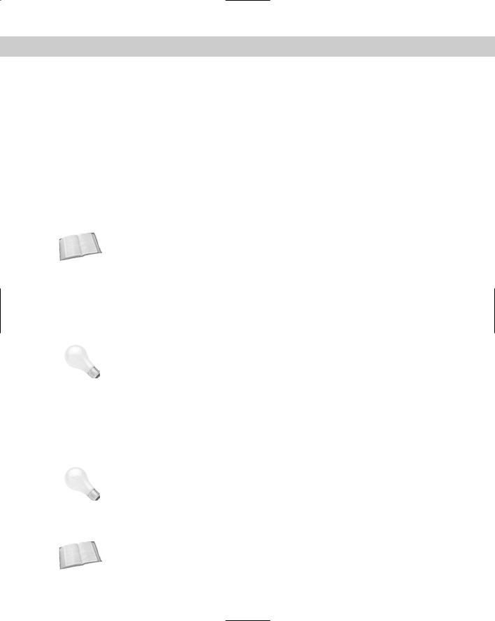
When the Vertex subobject mode is selected for an object, all vertices for the selected object appear as blue plus signs. The Vertex Ticks option displays all object vertices in this same way without requiring the Vertex subobject mode. Figure 6-10 shows the deer mesh with this option enabled.
Figure 6-10: The Vertex Ticks option displays all vertices as small blue tick marks.
The Trajectory option displays any animated motions as a spline path.
Cross- |
To learn more about using animated motion paths, see Chapter 30, “Animation Basics.” |
Reference |
|
202 Part II Working with Objects
|
The Ignore Extents option causes an object to be ignored when you are using the Zoom |
|
|
Extents button in the Viewport Navigation controls. For example, if you have a camera or |
|
|
light positioned at a distance from the objects in the scene, then anytime you use the Zoom |
|
|
Extents All button, the center objects are so small that you cannot see them because the |
|
|
Zoom Extents needs to include the distance light. If you set the Ignore Extent option for the |
|
|
camera or light, then the Zoom Extents All button zooms in on just the geometry objects. |
|
|
When objects are frozen, they appear dark gray, but if the Show Frozen in Gray option is |
|
|
disabled, then the object appears as it normally does in the viewport. |
|
|
The Vertex Color option displays the colors of any Editable Mesh vertices that have been |
|
|
assigned colors. You can select to use Vertex Color, Vertex Illumination, Vertex Alpha, Map |
|
|
Channel Color, or Soft Selection Color. The Shaded button causes the meshes to be shaded |
|
|
by the vertex colors. If the Shaded button is disabled, the object is unshaded. You can assign |
|
|
vertex colors only to editable meshes, editable polys, and editable patches. If the Map |
|
|
Channel Color option is selected, you can specify the Map Channel. |
|
Cross- |
|
For more information about vertex colors, check out Chapter 20, “Creating and Applying |
Reference |
Simple Materials.” |
|
|
|
|
|
Setting rendering controls |
|
In the Object Properties dialog box, the Rendering Controls section includes options that |
|
affect how an object is rendered. |
|
The Visibility spinner defines a value for how opaque (non-transparent) an object is. A value |
|
of 1 makes the object completely visible. A setting of 0.1 makes the object almost transparent. |
|
The Inherit Visibility option causes an object to adopt the same visibility setting as its parent. |
Tip |
The Visibility option can also be animated for making objects slowly disappear. |
|
The Renderable option determines whether or not the object is rendered. If this option isn’t |
|
selected, then the rest of the options are disabled because they don’t have any effect if the |
|
object isn’t rendered. The Renderable option is useful if you have a complex object that takes |
|
a while to render. You can disable the renderability of the single object to quickly render the |
|
other objects in the scene. |
|
You can use the Visible to Camera and Visible to Reflection/Refraction options to make |
|
objects invisible to the camera or to any reflections or refractions. This feature can be useful |
|
when you are test-rendering scene elements and raytraced objects. |
Tip |
If an object has the Visible to Camera option disabled and the Cast Shadows option enabled, |
|
then the object isn’t rendered, but its shadows are. |
|
The Receive Shadows and Cast Shadows options control how shadows are rendered for the |
|
selected object. The Apply Atmospherics options enable or disable rendering atmospherics. |
|
Atmospheric effects can increase the rendering time by a factor of 10, in some cases. |
Cross- |
Atmospheric effects are covered in Chapter 42, “Using Atmospheric Effects.” |
Reference |
|

Chapter 6 Selecting Objects and Setting Object Properties |
203 |
The Render Occluded Objects option causes the rendering engine to render all objects that are hidden behind the selected object. The hidden or occluded objects can have glows or other effects applied to them that would show up if rendered.
You use the G-Buffer Object Channel value to apply Render or Video Post effects to an object. By matching the Object Channel value to an effect ID, you can make an object receive an effect.
Cross- |
Render effects are covered in Chapter 43, “Using Render Elements and Effects,” and the |
Reference |
Video Post interface is covered in Chapter 47, “Using the Video Post Interface.” |
|
Enabling Motion Blur
You can also set Motion Blur from within the Object Properties dialog box. The Motion Blur effect causes objects that move fast (such as the Road Runner) to be blurred (which is useful in portraying speed). The render engine accomplishes this effect by rendering multiple copies of the object or image.
Cross- |
More information on these blur options is in Chapter 41, “Rendering Basics.” |
Reference |
|
The Object Properties dialog box can set two different types of Motion Blur: Object and Image. Object motion blur affects only the object and is not affected by the camera movement. Image motion blur applies the effect to the entire image and is applied after rendering.
Cross- A third type of Motion Blur is called Scene Motion Blur and is available in the Video Post Reference interface. See Chapter 47, “Using the Video Post Interface,” for information on using Scene
Motion Blur.
You can turn the Enabled option on and off as an animation progresses, allowing you to motion blur select sections of your animation sequence. The Multiplier value is enabled only for the Image Motion Blur type. It is used to set the length of the blur effect. The higher the Multiplier value, the longer the blurring streaks. The Motion Blur settings found in the Object Properties dialog box can be overridden by the settings in the Render Scene dialog box.
Caution |
If the Motion Blur option in the Object Properties dialog box is enabled but the Motion Blur |
|
option in the Renderer panel of the Render Scene dialog box is disabled, then motion |
|
blur will not be included in the final rendered image. |
Using the Advanced Lighting and mental ray panels
The second and third panels in the Object Properties dialog box contain object settings for working with Advanced Lighting and the mental ray renderer. Using the settings in the Advanced Lighting panel, you can exclude an object from any Advanced Lighting calculations, set an object to cast shadows and receive illumination, and set the number of refine iterations to complete.
The mental ray panel includes options for making an object generate and/or receive caustics and global illumination.