

158 Part I Learning the Max Interface
Cross- Check out Chapter 48, “Automating with MAXScript” for more on MAXScript commands and Reference preferences.
Radiosity preferences
The Radiosity panel includes settings that determine how radiosity is processed, whether advanced lighting options are saved with the scene file, and whether Reflectance and Transmittance are displayed in the Material Editor. You can also specify whether radiosity is displayed in the viewports. You can also disable advanced lighting warnings.
Cross- Check out Chapter 29, “Advanced Lighting and Radiosity,” for greater detail on Radiosity Reference preferences.
mental ray preferences
The mental ray panel includes settings that determine how the mental ray rendering engine acts. Using this panel, you can enable mental ray extensions, cause brackets to be shown as the renderer progresses, and clear the frame before rendering. Additional settings are available for handling errors and logs.
Cross- |
Check out Chapter 44, “Raytracing and mental ray,” for more detail on the mental ray renderer. |
Reference |
|
Summary
You can customize the Max interface in many ways. Most of these customization options are included under the Customize menu. In this chapter, you learned how to use this menu and its commands to customize many aspects of the interface. Customizing makes the Max interface more efficient and comfortable for you.
Specifically, this chapter covered the following topics:
Using the Customize User Interface dialog box to customize keyboard shortcuts, toolbars, quadmenus, menus, and colors
Customizing buttons on the Modify and Utility panels
Saving and loading custom interfaces
Configuring paths
Setting system units
Setting preferences
The next part is Part II, “Working with Objects.” The first chapter covers the primitive objects and gets some objects into a scene for you to work with.
|
|
|

Working with Objects
P A R T
II
In This Part
Chapter 5
Creating and Editing
Primitive Objects
Chapter 6
Selecting Objects and
Setting Object
Properties
Chapter 7
Cloning Objects and
Creating Object Arrays
Chapter 8
Grouping and
Linking Objects
Chapter 9
Working with the
Schematic View
Chapter 10
Transforming Objects —
Translate, Rotate, and
Scale
Chapter 11
Introducing Modifiers for Basic Object Deformation

Creating and
Editing Primitive
Objects
So what exactly did the Romans use to build their civilization? The answer is lots and lots of basic blocks. The basic building blocks
in Max are called primitives. You can use these basic primitives to start any modeling job. After you create a primitive, you can then bend it, stretch it, smash it, or cut it to create new objects, but for now, we focus on using primitives in their default shape.
This chapter covers the basics of primitive object types and introduces the various primitive objects, including how to accurately create and control them. You also use these base objects in the coming chapters to learn about selecting, cloning, grouping, and transforming.
Modeling is covered in depth in Part III, but first you need to learn how to create some basic blocks and move them around. Later, you can work on building a civilization. I’m sure Rome would be jealous.
Creating Primitive Objects
Max is all about creating objects and scenes, so it’s appropriate that one of the first things to learn is how to create objects. Although you can create complex models and objects, Max includes many simple, default geometric objects called primitives that you can use as a starting point. Creating these primitive objects can be as easy as clicking and dragging in a viewport.
Using the Create panel
The creation of all default Max objects, such as primitive spheres, shapes, lights, and cameras, starts with the Create panel (or the Create menu, which leads to the Create panel). This panel is the first panel in the Command Panel, indicated by an icon of an arrow pointing to a star.
Of all the panels in the Command Panel, only the Create panel (see Figure 5-1) includes both categories and subcategories. After you click the Create tab in the Command Panel, seven category icons are displayed. From left to right, they are Geometry, Shapes, Lights, Cameras, Helpers, Space Warps, and Systems.
C 5H A P T E R
In This Chapter
Creating primitive objects
Naming objects and setting object colors
Using creation methods
Setting object parameters
Exploring the various primitive types

162 Part II Working with Objects
When you select the Geometry button (which has an icon of a sphere on it), a dropdown list with several subcategories appears directly below the category icons. The
first available subcategory is Standard Primitives. When you select this subcategory, several text buttons appear that enable you to create some simple primitive objects.
Note |
The second subcategory is called Extended Primitives. It also includes primitive objects. |
Create panel
 Category icons
Subcategory drop-down list
Figure 5-1: The Create panel includes categories and subcategories.
As an example, click the button labeled Sphere (not to be confused with the Geometry category, which has a sphere icon). Several rollouts appear at the bottom of the Command Panel — these rollouts for the Sphere primitive object include Name and Color, Creation Method, Keyboard Entry, and Parameters. The rollouts for each primitive are slightly different, as well as the parameters within each rollout.
If you want to ignore these rollouts and just create a sphere, simply click and drag within one of the viewports, and a sphere object appears. Figure 5-2 shows the new sphere and its parameters.
When an object button, such as the Sphere button, is selected, it turns dark yellow. This color change reminds you that you are in creation mode. Clicking and dragging within any viewport creates an additional sphere. While in creation mode, you can create many spheres by clicking and dragging several times in one of the viewports. To get out of creation mode, rightclick in the active viewport and click the Select Object button or one of the transform buttons on the main toolbar.

Chapter 5 Creating and Editing Primitive Objects |
163 |
Figure 5-2: You can create primitive spheres easily by dragging in a viewport.
Using the Create menu
The Create menu offers quick access to the buttons in the Create panel. All the objects that you can create using the Create panel you can access using the Create menu. Selecting an object from the Create menu opens the Create panel and automatically selects the corresponding button. You still need to click and drag in the viewport to create the object.
New |
New to 3ds max 6 is the fact that almost all Create panel objects have a corresponding menu |
Feature |
command found in the Create menu. |
|
Naming and renaming objects
Every object in the scene can have both a name and color assigned to it. Each object is given a default name and random color when first created. The default name is the type of object followed by a number. For example, when you create a sphere object, Max labels it “Sphere01.” These default names aren’t very exciting and can be confusing if you have many objects. You can change the object’s name at any time by modifying the Name field in the Name and Color rollout of the Command Panel.
164 Part II Working with Objects
Cross- |
Names and colors are useful for locating and selecting objects, as you find out in Chapter 6, |
Reference |
“Selecting Objects and Setting Object Properties.” |
|
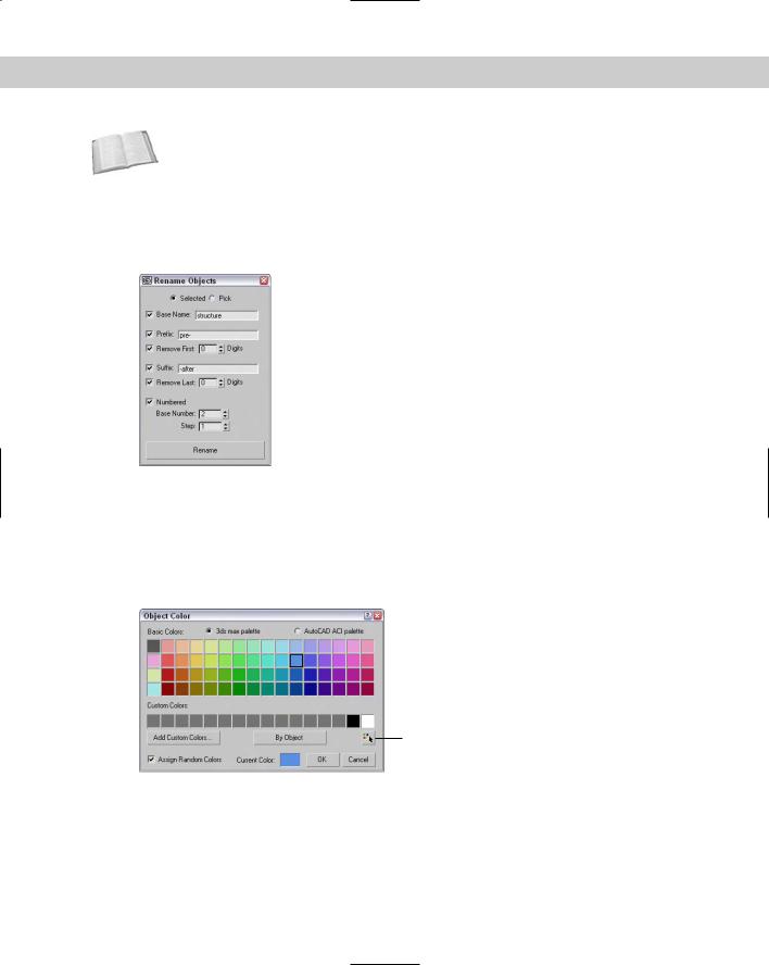
The Tools Rename menu command opens a dialog box that lets you change the object name of several objects at once. The Rename Objects dialog box, shown in Figure 5-3, lets you set the Base Name along with a Prefix, a Suffix, or a number. These new names can be applied to the selected objects or to the specific objects that you pick from the Select Objects dialog box.
Figure 5-3: The Rename Objects dialog box can rename several objects at once.
Assigning colors
The object color is shown in the color swatch to the right of the object name. This color is the color that is used to display the object within the viewports and to render the object if a material isn’t applied. To change an object’s color, just click the color swatch next to the Name field to make the Object Color dialog box appear. This dialog box, shown in Figure 5-4, lets you select a different color or pick a custom color.
Select by Color button
Figure 5-4: You use the Object Color dialog box to define the color of objects displayed in the viewports.
Chapter 5 Creating and Editing Primitive Objects |
165 |
The Object Color dialog box includes the standard 3ds max palette and the AutoCAD ACI palette. The AutoCAD palette has many more colors than the Max palette, but the Max palette allows a row of custom colors. Above the Cancel button is the Select by Color button. Click this button to open the Select Objects dialog box where you can select all the objects that have a certain color.
With the Object Color dialog box, if the Assign Random Colors option is selected, then a random color from the palette is chosen every time a new object is created. If this option is not selected, the color of all new objects is the same until you choose a different object color.
Making objects different colors allows you to more easily distinguish between two objects for selection and transformation.
The Object Color dialog box also includes a button that toggles between By Layer and By Objects. Using this button, you can cause objects to accept color according to their object definition or based on the layer of which they are a part.
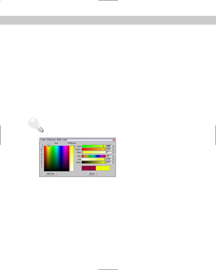
You can select custom colors by clicking the Add Custom Colors button. This button opens a Color Selector dialog box, shown in Figure 5-5. Selecting a color and clicking the Add Color button adds the selected color to the row of Custom Colors in the Object Color palette. You can also open the Color Selector by clicking on the Current Color swatch. The current color can then be dragged to the row of Custom Colors.
Tip |
You can fill the entire row of Custom Colors by clicking repeatedly on the Add Color button. |
Figure 5-5: The Color Selector dialog box lets you choose new custom colors.
The Color Selector dialog box defines colors using the RGB (red, green, and blue) and HSV (hue, saturation, and value) color systems. Another way to select colors is to drag the cursor around the rainbow palette to the left. After you find the perfect custom color to add to the Object Color dialog box, click the Add Color button. This custom color is then available wherever the Object Color dialog box is opened.
Object colors are also important because you can use them to select and filter objects. For example, the Selection Floater (open by choosing Tools Selection Floater) includes a Sort by Color setting. You can also choose Edit Select by Color menu (or click the Select by Color button) to select only objects that match a selected color.
166 Part II Working with Objects
Note |
You can set objects to display an object’s default color or its Material Color. These options are |
|
in the Display Color rollout under the Display panel (the fifth tab from the left in the |
|
Command Panel with an icon of a monitor). You can set them differently for Wireframe and |
|
Shaded views. |
Using the Color Clipboard
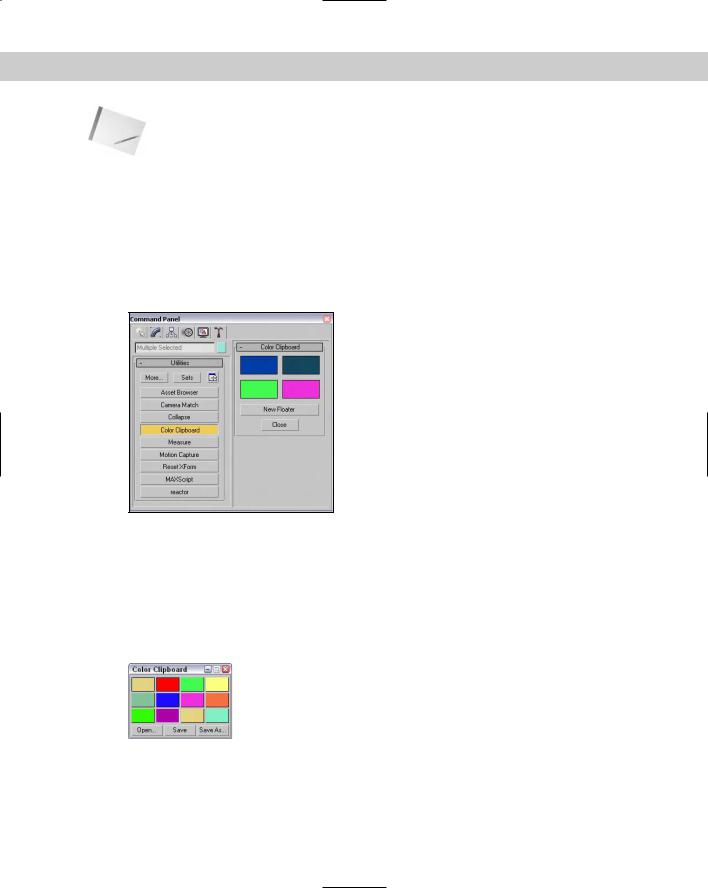
The object color is one of the first places where colors are encountered, but it certainly won’t be the last. If you find a specific color that you like and want to use elsewhere, you can use the Color Clipboard utility to carry colors to other interfaces. You can access this utility using the Tools Color Clipboard menu command, which opens the Utilities panel, as shown in Figure 5-6.
Figure 5-6: The Color Clipboard utility offers a way to transport colors.
When selected, the Color Clipboard appears as a rollout in the Utilities panel and includes four color swatches. These color swatches can be dragged to other interfaces like the Material Editor. Clicking on any of these swatches launches the Color Selector. The New Floater button opens a floatable Color Clipboard that holds 12 colors, shown in Figure 5-7. Using this clipboard, you can open and save color configurations. The files are saved as Color Clipboard Files with the .ccb extension.
Figure 5-7: The Color Clipboard floating palette can hold 12 colors.
Chapter 5 Creating and Editing Primitive Objects |
167 |
|
Using different creation methods |
|
You actually have a couple of ways to create primitive objects by dragging in a viewport. With |
|
the first method, the first place you click sets the object’s initial position. You then need to |
|
drag the mouse to define the object’s first dimension and then click again to set each addi- |
|
tional dimension, if needed. Primitive objects with a different number of dimensions require a |
|
different number of clicks and drags. |
|
For example, a sphere is one of the simplest objects to create. To create a sphere, click in a |
|
viewport to set the location of the sphere’s center, drag the mouse to the desired radius, and |
|
release the mouse button to complete. A Box object, on the other hand, requires a click and |
|
drag move to define the base (width and depth), and another drag and click again to set the |
|
height. If you ever get lost when defining these dimensions, check the Prompt Line to see |
|
what dimension the interface expects next. |
|
When you click a primitive object button, the Creation Method rollout appears and offers |
|
different methods for creating the primitives. For example, click the Sphere button, and the |
|
Creation Method rollout displays two options: Edge and Center. When you choose the Edge |
|
method, the first viewport click sets one edge of the sphere, and dragging and clicking again |
|
sets the diameter of the sphere. The default Center creation method defines the sphere’s cen- |
|
ter location; dragging sets the sphere’s radius. The creation method for each primitive can be |
|
different. For example, the Box primitive object has a creation method for creating perfect |
|
cubes. Table 5-1 shows the number of clicks required to create an object and the creation |
|
methods for each primitive object. |
Tip |
If you’re dragging to create a primitive object and halfway through its creation you change |
|
your mind, you can right-click to eliminate the creation of the object. |
Table 5-1: Primitive Object Creation Methods
|
Number of Viewport |
Default Creation |
Other Creation |
Primitive Object |
Clicks to Create |
Method |
Method |
|
|
|
|
Box |
2 |
Box |
Cube |
Cone |
3 |
Center |
Edge |
Sphere |
1 |
Center |
Edge |
GeoSphere |
1 |
Center |
Diameter |
Cylinder |
2 |
Center |
Edge |
Tube |
3 |
Center |
Edge |
Continued
168 Part II Working with Objects
Table 5-1 (continued)
|
|
Number of Viewport |
Default Creation |
Other Creation |
|
Primitive Object |
Clicks to Create |
Method |
Method |
|
|
|
|
|
|
Torus |
2 |
Center |
Edge |
|
Pyramid |
2 |
Base/Apex |
Center |
|
Teapot |
1 |
Center |
Edge |
|
Plane |
1 |
Rectangular |
Square |
|
Hedra |
1 |
- |
- |
|
Torus Knot |
2 |
Radius |
Diameter |
|
ChamferBox |
3 |
Box |
Cube |
|
ChamferCyl |
3 |
Center |
Edge |
|
OilTank |
3 |
Center |
Edge |
|
Capsule |
2 |
Center |
Edge |
|
Spindle |
3 |
Center |
Edge |
|
L-Ext |
3 |
Corners |
Center |
|
Gengon |
3 |
Center |
Edge |
|
C-Ext |
3 |
Corners |
Center |
|
RingWave |
2 |
- |
- |
|
Hose |
2 |
- |
- |
|
Prism |
3 |
Base/Apex |
Isosceles |
|
|
|
|
|

Chapter 5 Creating and Editing Primitive Objects |
169 |
Note Some primitive objects, such as the Hedra, RingWave, and Hose, don’t have any creation methods.
Using the Keyboard Entry rollout for precise dimensions
When creating a primitive object, you can define its location and dimensions by clicking in a viewport and dragging, or you can enter precise values in the Keyboard Entry rollout, located in the Create panel. Within this rollout, you can enter the offset XYZ values for positioning the origin of the primitive and the dimensions of the object. The offset values are defined relative to the active construction plane that is usually the Home Grid.
When all the dimension fields are set, click the Create button to create the actual primitive. You can create multiple objects by clicking the Create button several times. After a primitive is created, altering the fields in the Keyboard Entry rollout has no effect on the current object, but you can always use the Undo feature to try again.
Altering object parameters
The final rollout for all primitive objects is the Parameters rollout. This rollout holds all the various settings for the object. Compared to the Keyboard Entry rollout, which you can use only when creating the primitive, you can use the Parameters rollout to alter the primitive’s parameters before or after the creation of the object. For example, increasing the Radius value after creating an object makes an existing sphere larger.
The parameters are different for each primitive object, but you can generally use them to control the dimensions, the number of segments that make up the object, and whether the object is sliced into sections. You can also select the Generate Mapping Coordinates option (which automatically creates material mapping coordinates that are used to position maps).
Note After you deselect an object, the Parameters rollout disappears from the Create tab and moves to the Modify tab. You can make future parameter adjustments by selecting an object and clicking the Modify tab.
Recovering from mistakes and deleting objects
Before going any further, you need to be reminded how to undo the last action with the Undo menu command. The Undo (Ctrl+Z) menu command will undo the last action, whether it’s creating an object or changing a parameter. The Redo (Ctrl+Y) menu command lets you redo an action that was undone.
You can set the levels of undo in the Preference Settings dialog box. If you right-click on either the Undo or Redo buttons on the main toolbar, a list of recent actions is displayed. You can select any action from this list to be undone.
The Edit Delete menu command removes the selected object (or objects) from the scene. (The keyboard shortcut for this command is, luckily, the Delete key, because anything else would be confusing.)
170 Part II Working with Objects
Tutorial: Exploring the Platonic solids
Among the many discoveries of Plato, an ancient Greek mathematician and philosopher, were the mathematical formulas that defined perfect geometric solids. A perfect geometric solid is one that is made up of polygon faces that are consistent throughout the object. The five solids that meet these criteria have come to be known as the Platonic solids.
Using Max, you can create and explore these interesting geometric shapes. Each of these shapes is available as a primitive object using the Hedra primitive object. The Hedra primitive object is one of the Extended Primitives.
To create the five Platonic solids as primitive objects, follow these steps:
1.Open the Create panel, click the Geometry category button, and select Extended Primitives from the subcategory drop-down list. Click the Hedra button to enter Hedra creation mode, or select the Create Extended Primitives Hedra menu command.
2.Click in the Top viewport, and drag to the left to create a simple Tetrahedron object.
After the object is created, you can adjust its settings by altering the settings in the Parameters rollout.
3.Select the Tetra option in the Parameters rollout, set the P value in the Family Parameters section to 1.0, and enter a value of 50 for the Radius. Be sure to press the Enter key after entering a value to update the object. Enter the name Tetrahedron in the Object Name field.
4.Click and drag again in the Top viewport to create another hedra object. In the Parameters rollout, select the Cube/Octa option, and enter a value of 1.0 in the Family Parameter’s P field and a value of 50 in the Radius field. Name this object Octagon.
5.Drag in the Top viewport to create another object. The Cube/Octa option is still selected. Enter a value of 1.0 in the Family Parameter’s Q field this time, and set the Radius to 50. Name this object Cube.
6.Drag in the Top viewport again to create the fourth hedra object. In the Parameters rollout, select the Dodec/Icos option, enter a value of 1.0 in the P field, and set the Radius value to 50. Name the object Icosahedron.
7.Drag in the Top viewport to create the final object. With the Dodec/Icos option set, enter 1.0 for the Q value, and set the Radius to 50. Name this object Dodecahedron.
8.To get a good look at the objects, click the Perspective viewport, press the Zoom Extents button, and maximize the viewport by clicking the Min/Max Toggle (or press Alt+W) in the lower-right corner of the window.
Figure 5-8 shows the five perfect solid primitive objects. Using the Modify panel, you can return to these objects and change their parameters to learn the relationships between them. Later in this chapter, you can read about the Hedra primitive in greater detail.