

- •Preface
- •About This Book
- •Acknowledgments
- •Contents at a Glance
- •Contents
- •Relaxing at the Beach
- •Dressing the Scene
- •Animating Motion
- •Rendering the Final Animation
- •Summary
- •The Interface Elements
- •Using the Menus
- •Using the Toolbars
- •Using the Viewports
- •Using the Command Panel
- •Using the Lower Interface Bar Controls
- •Interacting with the Interface
- •Getting Help
- •Summary
- •Understanding 3D Space
- •Using the Viewport Navigation Controls
- •Configuring the Viewports
- •Working with Viewport Backgrounds
- •Summary
- •Working with Max Scene Files
- •Setting File Preferences
- •Importing and Exporting
- •Referencing External Objects
- •Using the File Utilities
- •Accessing File Information
- •Summary
- •Customizing Modify and Utility Panel Buttons
- •Working with Custom Interfaces
- •Configuring Paths
- •Selecting System Units
- •Setting Preferences
- •Summary
- •Creating Primitive Objects
- •Exploring the Primitive Object Types
- •Summary
- •Selecting Objects
- •Setting Object Properties
- •Hiding and Freezing Objects
- •Using Layers
- •Summary
- •Cloning Objects
- •Understanding Cloning Options
- •Mirroring Objects
- •Cloning over Time
- •Spacing Cloned Objects
- •Creating Arrays of Objects
- •Summary
- •Working with Groups
- •Building Assemblies
- •Building Links between Objects
- •Displaying Links and Hierarchies
- •Working with Linked Objects
- •Summary
- •Using the Schematic View Window
- •Working with Hierarchies
- •Setting Schematic View Preferences
- •Using List Views
- •Summary
- •Working with the Transformation Tools
- •Using Pivot Points
- •Using the Align Commands
- •Using Grids
- •Using Snap Options
- •Summary
- •Exploring the Modifier Stack
- •Exploring Modifier Types
- •Summary
- •Exploring the Modeling Types
- •Working with Subobjects
- •Modeling Helpers
- •Summary
- •Drawing in 2D
- •Editing Splines
- •Using Spline Modifiers
- •Summary
- •Creating Editable Mesh and Poly Objects
- •Editing Mesh Objects
- •Editing Poly Objects
- •Using Mesh Editing Modifiers
- •Summary
- •Introducing Patch Grids
- •Editing Patches
- •Using Modifiers on Patch Objects
- •Summary
- •Creating NURBS Curves and Surfaces
- •Editing NURBS
- •Working with NURBS
- •Summary
- •Morphing Objects
- •Creating Conform Objects
- •Creating a ShapeMerge Object
- •Creating a Terrain Object
- •Using the Mesher Object
- •Working with BlobMesh Objects
- •Creating a Scatter Object
- •Creating Connect Objects
- •Modeling with Boolean Objects
- •Creating a Loft Object
- •Summary
- •Understanding the Various Particle Systems
- •Creating a Particle System
- •Using the Spray and Snow Particle Systems
- •Using the Super Spray Particle System
- •Using the Blizzard Particle System
- •Using the PArray Particle System
- •Using the PCloud Particle System
- •Using Particle System Maps
- •Controlling Particles with Particle Flow
- •Summary
- •Understanding Material Properties
- •Working with the Material Editor
- •Using the Material/Map Browser
- •Using the Material/Map Navigator
- •Summary
- •Using the Standard Material
- •Using Shading Types
- •Accessing Other Parameters
- •Using External Tools
- •Summary
- •Using Compound Materials
- •Using Raytrace Materials
- •Using the Matte/Shadow Material
- •Using the DirectX 9 Shader
- •Applying Multiple Materials
- •Material Modifiers
- •Summary
- •Understanding Maps
- •Understanding Material Map Types
- •Using the Maps Rollout
- •Using the Map Path Utility
- •Using Map Instances
- •Summary
- •Mapping Modifiers
- •Using the Unwrap UVW modifier
- •Summary
- •Working with Cameras
- •Setting Camera Parameters
- •Summary
- •Using the Camera Tracker Utility
- •Summary
- •Using Multi-Pass Cameras
- •Creating Multi-Pass Camera Effects
- •Summary
- •Understanding the Basics of Lighting
- •Getting to Know the Light Types
- •Creating and Positioning Light Objects
- •Viewing a Scene from a Light
- •Altering Light Parameters
- •Working with Photometric Lights
- •Using the Sunlight and Daylight Systems
- •Using Volume Lights
- •Summary
- •Selecting Advanced Lighting
- •Using Local Advanced Lighting Settings
- •Tutorial: Excluding objects from light tracing
- •Summary
- •Understanding Radiosity
- •Using Local and Global Advanced Lighting Settings
- •Working with Advanced Lighting Materials
- •Using Lighting Analysis
- •Summary
- •Using the Time Controls
- •Working with Keys
- •Using the Track Bar
- •Viewing and Editing Key Values
- •Using the Motion Panel
- •Using Ghosting
- •Animating Objects
- •Working with Previews
- •Wiring Parameters
- •Animation Modifiers
- •Summary
- •Understanding Controller Types
- •Assigning Controllers
- •Setting Default Controllers
- •Examining the Various Controllers
- •Summary
- •Working with Expressions in Spinners
- •Understanding the Expression Controller Interface
- •Understanding Expression Elements
- •Using Expression Controllers
- •Summary
- •Learning the Track View Interface
- •Working with Keys
- •Editing Time
- •Editing Curves
- •Filtering Tracks
- •Working with Controllers
- •Synchronizing to a Sound Track
- •Summary
- •Understanding Your Character
- •Building Bodies
- •Summary
- •Building a Bones System
- •Using the Bone Tools
- •Using the Skin Modifier
- •Summary
- •Creating Characters
- •Working with Characters
- •Using Character Animation Techniques
- •Summary
- •Forward versus Inverse Kinematics
- •Creating an Inverse Kinematics System
- •Using the Various Inverse Kinematics Methods
- •Summary
- •Creating and Binding Space Warps
- •Understanding Space Warp Types
- •Combining Particle Systems with Space Warps
- •Summary
- •Understanding Dynamics
- •Using Dynamic Objects
- •Defining Dynamic Material Properties
- •Using Dynamic Space Warps
- •Using the Dynamics Utility
- •Using the Flex Modifier
- •Summary
- •Using reactor
- •Using reactor Collections
- •Creating reactor Objects
- •Calculating and Previewing a Simulation
- •Constraining Objects
- •reactor Troubleshooting
- •Summary
- •Understanding the Max Renderers
- •Previewing with ActiveShade
- •Render Parameters
- •Rendering Preferences
- •Creating VUE Files
- •Using the Rendered Frame Window
- •Using the RAM Player
- •Reviewing the Render Types
- •Using Command-Line Rendering
- •Creating Panoramic Images
- •Getting Printer Help
- •Creating an Environment
- •Summary
- •Creating Atmospheric Effects
- •Using the Fire Effect
- •Using the Fog Effect
- •Summary
- •Using Render Elements
- •Adding Render Effects
- •Creating Lens Effects
- •Using Other Render Effects
- •Summary
- •Using Raytrace Materials
- •Using a Raytrace Map
- •Enabling mental ray
- •Summary
- •Understanding Network Rendering
- •Network Requirements
- •Setting up a Network Rendering System
- •Starting the Network Rendering System
- •Configuring the Network Manager and Servers
- •Logging Errors
- •Using the Monitor
- •Setting up Batch Rendering
- •Summary
- •Compositing with Photoshop
- •Video Editing with Premiere
- •Video Compositing with After Effects
- •Introducing Combustion
- •Using Other Compositing Solutions
- •Summary
- •Completing Post-Production with the Video Post Interface
- •Working with Sequences
- •Adding and Editing Events
- •Working with Ranges
- •Working with Lens Effects Filters
- •Summary
- •What Is MAXScript?
- •MAXScript Tools
- •Setting MAXScript Preferences
- •Types of Scripts
- •Writing Your Own MAXScripts
- •Learning the Visual MAXScript Editor Interface
- •Laying Out a Rollout
- •Summary
- •Working with Plug-Ins
- •Locating Plug-Ins
- •Summary
- •Low-Res Modeling
- •Using Channels
- •Using Vertex Colors
- •Rendering to a Texture
- •Summary
- •Max and Architecture
- •Using AEC Objects
- •Using Architectural materials
- •Summary
- •Tutorial: Creating Icy Geometry with BlobMesh
- •Tutorial: Using Caustic Photons to Create a Disco Ball
- •Summary
- •mental ray Rendering System
- •Particle Flow
- •reactor 2.0
- •Schematic View
- •BlobMesh
- •Spline and Patch Features
- •Import and Export
- •Shell Modifier
- •Vertex Paint and Channel Info
- •Architectural Primitives and Materials
- •Minor Improvements
- •Choosing an Operating System
- •Hardware Requirements
- •Installing 3ds max 6
- •Authorizing the Software
- •Setting the Display Driver
- •Updating Max
- •Moving Max to Another Computer
- •Using Keyboard Shortcuts
- •Using the Hotkey Map
- •Main Interface Shortcuts
- •Dialog Box Shortcuts
- •Miscellaneous Shortcuts
- •System Requirements
- •Using the CDs with Windows
- •What’s on the CDs
- •Troubleshooting
- •Index

Chapter 12 Modeling Basics 345
Modeling Helpers
In the Create panel (and the Create menu) is a category of miscellaneous objects called Helpers (the icon looks like a tape measure). These objects are useful in positioning objects and measuring dimensions. The buttons in the Helper category include Dummy, Grid, Point, Tape, Protractor, and Compass.
Using Dummy and Point objects
The Dummy object is a useful object for controlling complex object hierarchies. A Dummy object appears in the viewports as a simple cube with a pivot point at its center, but the object will not be rendered and has no parameters. It is used only as an object about which to transform objects. For example, you could create a Dummy object that the camera could follow through an animation sequence. Dummy objects are used in many examples throughout the remainder of the book.
The Point object is very similar to the Dummy object in that it also is not rendered and has minimal parameters. A Point object defines a point in space and is identified as an X, as an Axis Tripod, or as a simple Box. The Center Marker option places an X at the center of the Point object (so X really does mark the spot). The Axis Tripod option displays the X, Y, and Z axes, and the Box option displays the Point object as a Box. The Size value determines how big the Point object is. The Constant Screen Size option keeps the size of the Point object constant, regardless of how much you zoom in or out of the scene. The Draw on Top option draws the Point object above all other scene objects, making it easy to locate. The main purpose for the Point object is to mark positions within the scene.
Caution |
Point objects are difficult to see and easy to lose. If you use a point object, but sure to name |
|
it so you can find it easily in the Select by Name dialog box. |
Measuring coordinate distances
The Helpers category also includes several handy utilities for measuring dimensions and directions. These are the Tape, Protractor, and Compass objects. The units are all based on the current selected system units.
Using the Measure Distance tool
In the Tools menu is a command to Measure Distance. This tool works easily. Just select it, click at the starting point and again at the ending point, and the distance between the two clicks is shown in the Status Bar at the bottom of the interface. Measure Distance also reports the Delta values in the X, Y, and Z directions. You can use this tool with the Snap feature enabled for accurate measurements.
Using the Tape helper
You use the Tape object to measure distances. To use it, simply drag the distance that you would like to measure and view the resulting dimension in the Parameters rollout. You can also set the length of the Tape object using the Specify Length option. You can move and reposition the endpoints of the Tape object with the Select and Move button, but the Rotate and Scale buttons have no effect.

346 Part III Modeling
Using the Protractor helper
The Protractor object works in a manner similar to the Tape object, but it measures the angle between two objects. To use the Protractor object, click in a viewport to position the Protractor object. (The Protractor object looks like two pyramids aligned point to point and represents the origin of the angle.) Then click the Pick Object 1 button, and select an object in the scene. A line is drawn from the Protractor object to the selected object. Next, click the Pick Object 2 button. The angle-formed objects and the Protractor object are displayed in the Parameters rollout. The value changes as either of the selected objects or the Protractor is moved.
Note All measurement values are presented in gray fields within the Parameters rollout. This gray field indicates that the value cannot be modified.
Using the Compass helper
The Compass object identifies North, East, West, and South positions on a planar star-shaped object.
Cross- |
The Grid helper object is discussed along with grids in Chapter 10, “Transforming Objects — |
Reference |
Translate, Rotate, and Scale.” Compass object is mainly used in conjunction with the Sunlight |
|
|
|
System, which you can learn about in Chapter 27, “Basic Lighting Techniques.” |
Using the Measure utility
In the Utilities panel is another useful tool for getting the scoop on the current selected object: the Measure utility. You can open the Measure utility as a floater dialog box, shown in Figure 12-9. This dialog box displays the object’s name along with its Surface Area, Volume, Center of Mass, Length (for shapes), and Dimensions. It also includes an option to Lock the current Selection.
Figure 12-9: The Measure utility dialog box displays some useful information.
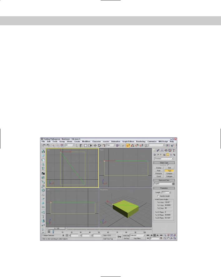
Tutorial: Testing the Pythagorean Theorem
I always trusted my teachers in school to tell me the truth, but maybe they were just making it all up, especially my math teacher. (He did have shifty eyes, after all.) For my peace of mind, I want to test one of the mathematical principles he taught us, the Pythagorean Theorem. (What kind of name is that anyway?)
If I remember the theorem correctly, it says that the sum of the squares of the sides of a right triangle equals the hypotenuse squared. So, according to my calculations, a right triangle
Chapter 12 Modeling Basics 347
with a side of 3 and a side of 4 would have a hypotenuse of 5. Because Max is proficient at drawing shapes such as this one, we test the theorem by creating a box with a width of 40 and a height of 30 and then measuring the diagonal.
To test the Pythagorean Theorem, follow these steps:
1.Select the Create Standard Primitives Box menu command, and drag and click in the Top view to create a Box object. Change its parameters to 40 for the Length, 30 for the Width, and 10 for the Height values. Then right-click in the active viewport to exit Box creation mode, and press the Z key to zoom in on the Box object.
2.Right-click any of the Snap buttons on the main toolbar to open the Snap and Grid Settings dialog box, select the Snaps panel, and set the Snap feature to snap to vertices by selecting the Vertex option. Close the Grid and Snap Settings dialog box, and enable the 3D Snap feature by clicking on the Snap button in the main toolbar (or by pressing S).
3.Select the Create Helper Tape menu command.
4.In the Top viewport, move the cursor over the upper-left corner of the object, and click on the blue vertex that appears. Then drag down to the lower-right corner, and click the next blue vertex that appears. Note the measurement in the Parameters rollout.
Well, I guess my math teacher didn’t lie about this theorem, but I wonder whether he was correct about all those multiplication tables. Figure 12-10 shows the resulting box and measurement value.
Figure 12-10: I guess old Pythagoras was right. (Good thing I have Max to help me check.)

348 Part III Modeling
Summary
Understanding the basics of modeling helps you as you build scenes. In this chapter, you’ve seen several different object types that are available in Max. Many of these types have similar features such as Soft Selection. Several helper objects can assist as well. This chapter covered the following topics:
Understanding parametric objects and the various modeling types
Using subobjects and soft selections
Using Helper objects
Now that you have the basics covered, you’re ready to dive into the various modeling types. The first modeling type on the list is splines and shapes, which is covered in the next chapter.
|
|
|