

- •Preface
- •About This Book
- •Acknowledgments
- •Contents at a Glance
- •Contents
- •Relaxing at the Beach
- •Dressing the Scene
- •Animating Motion
- •Rendering the Final Animation
- •Summary
- •The Interface Elements
- •Using the Menus
- •Using the Toolbars
- •Using the Viewports
- •Using the Command Panel
- •Using the Lower Interface Bar Controls
- •Interacting with the Interface
- •Getting Help
- •Summary
- •Understanding 3D Space
- •Using the Viewport Navigation Controls
- •Configuring the Viewports
- •Working with Viewport Backgrounds
- •Summary
- •Working with Max Scene Files
- •Setting File Preferences
- •Importing and Exporting
- •Referencing External Objects
- •Using the File Utilities
- •Accessing File Information
- •Summary
- •Customizing Modify and Utility Panel Buttons
- •Working with Custom Interfaces
- •Configuring Paths
- •Selecting System Units
- •Setting Preferences
- •Summary
- •Creating Primitive Objects
- •Exploring the Primitive Object Types
- •Summary
- •Selecting Objects
- •Setting Object Properties
- •Hiding and Freezing Objects
- •Using Layers
- •Summary
- •Cloning Objects
- •Understanding Cloning Options
- •Mirroring Objects
- •Cloning over Time
- •Spacing Cloned Objects
- •Creating Arrays of Objects
- •Summary
- •Working with Groups
- •Building Assemblies
- •Building Links between Objects
- •Displaying Links and Hierarchies
- •Working with Linked Objects
- •Summary
- •Using the Schematic View Window
- •Working with Hierarchies
- •Setting Schematic View Preferences
- •Using List Views
- •Summary
- •Working with the Transformation Tools
- •Using Pivot Points
- •Using the Align Commands
- •Using Grids
- •Using Snap Options
- •Summary
- •Exploring the Modifier Stack
- •Exploring Modifier Types
- •Summary
- •Exploring the Modeling Types
- •Working with Subobjects
- •Modeling Helpers
- •Summary
- •Drawing in 2D
- •Editing Splines
- •Using Spline Modifiers
- •Summary
- •Creating Editable Mesh and Poly Objects
- •Editing Mesh Objects
- •Editing Poly Objects
- •Using Mesh Editing Modifiers
- •Summary
- •Introducing Patch Grids
- •Editing Patches
- •Using Modifiers on Patch Objects
- •Summary
- •Creating NURBS Curves and Surfaces
- •Editing NURBS
- •Working with NURBS
- •Summary
- •Morphing Objects
- •Creating Conform Objects
- •Creating a ShapeMerge Object
- •Creating a Terrain Object
- •Using the Mesher Object
- •Working with BlobMesh Objects
- •Creating a Scatter Object
- •Creating Connect Objects
- •Modeling with Boolean Objects
- •Creating a Loft Object
- •Summary
- •Understanding the Various Particle Systems
- •Creating a Particle System
- •Using the Spray and Snow Particle Systems
- •Using the Super Spray Particle System
- •Using the Blizzard Particle System
- •Using the PArray Particle System
- •Using the PCloud Particle System
- •Using Particle System Maps
- •Controlling Particles with Particle Flow
- •Summary
- •Understanding Material Properties
- •Working with the Material Editor
- •Using the Material/Map Browser
- •Using the Material/Map Navigator
- •Summary
- •Using the Standard Material
- •Using Shading Types
- •Accessing Other Parameters
- •Using External Tools
- •Summary
- •Using Compound Materials
- •Using Raytrace Materials
- •Using the Matte/Shadow Material
- •Using the DirectX 9 Shader
- •Applying Multiple Materials
- •Material Modifiers
- •Summary
- •Understanding Maps
- •Understanding Material Map Types
- •Using the Maps Rollout
- •Using the Map Path Utility
- •Using Map Instances
- •Summary
- •Mapping Modifiers
- •Using the Unwrap UVW modifier
- •Summary
- •Working with Cameras
- •Setting Camera Parameters
- •Summary
- •Using the Camera Tracker Utility
- •Summary
- •Using Multi-Pass Cameras
- •Creating Multi-Pass Camera Effects
- •Summary
- •Understanding the Basics of Lighting
- •Getting to Know the Light Types
- •Creating and Positioning Light Objects
- •Viewing a Scene from a Light
- •Altering Light Parameters
- •Working with Photometric Lights
- •Using the Sunlight and Daylight Systems
- •Using Volume Lights
- •Summary
- •Selecting Advanced Lighting
- •Using Local Advanced Lighting Settings
- •Tutorial: Excluding objects from light tracing
- •Summary
- •Understanding Radiosity
- •Using Local and Global Advanced Lighting Settings
- •Working with Advanced Lighting Materials
- •Using Lighting Analysis
- •Summary
- •Using the Time Controls
- •Working with Keys
- •Using the Track Bar
- •Viewing and Editing Key Values
- •Using the Motion Panel
- •Using Ghosting
- •Animating Objects
- •Working with Previews
- •Wiring Parameters
- •Animation Modifiers
- •Summary
- •Understanding Controller Types
- •Assigning Controllers
- •Setting Default Controllers
- •Examining the Various Controllers
- •Summary
- •Working with Expressions in Spinners
- •Understanding the Expression Controller Interface
- •Understanding Expression Elements
- •Using Expression Controllers
- •Summary
- •Learning the Track View Interface
- •Working with Keys
- •Editing Time
- •Editing Curves
- •Filtering Tracks
- •Working with Controllers
- •Synchronizing to a Sound Track
- •Summary
- •Understanding Your Character
- •Building Bodies
- •Summary
- •Building a Bones System
- •Using the Bone Tools
- •Using the Skin Modifier
- •Summary
- •Creating Characters
- •Working with Characters
- •Using Character Animation Techniques
- •Summary
- •Forward versus Inverse Kinematics
- •Creating an Inverse Kinematics System
- •Using the Various Inverse Kinematics Methods
- •Summary
- •Creating and Binding Space Warps
- •Understanding Space Warp Types
- •Combining Particle Systems with Space Warps
- •Summary
- •Understanding Dynamics
- •Using Dynamic Objects
- •Defining Dynamic Material Properties
- •Using Dynamic Space Warps
- •Using the Dynamics Utility
- •Using the Flex Modifier
- •Summary
- •Using reactor
- •Using reactor Collections
- •Creating reactor Objects
- •Calculating and Previewing a Simulation
- •Constraining Objects
- •reactor Troubleshooting
- •Summary
- •Understanding the Max Renderers
- •Previewing with ActiveShade
- •Render Parameters
- •Rendering Preferences
- •Creating VUE Files
- •Using the Rendered Frame Window
- •Using the RAM Player
- •Reviewing the Render Types
- •Using Command-Line Rendering
- •Creating Panoramic Images
- •Getting Printer Help
- •Creating an Environment
- •Summary
- •Creating Atmospheric Effects
- •Using the Fire Effect
- •Using the Fog Effect
- •Summary
- •Using Render Elements
- •Adding Render Effects
- •Creating Lens Effects
- •Using Other Render Effects
- •Summary
- •Using Raytrace Materials
- •Using a Raytrace Map
- •Enabling mental ray
- •Summary
- •Understanding Network Rendering
- •Network Requirements
- •Setting up a Network Rendering System
- •Starting the Network Rendering System
- •Configuring the Network Manager and Servers
- •Logging Errors
- •Using the Monitor
- •Setting up Batch Rendering
- •Summary
- •Compositing with Photoshop
- •Video Editing with Premiere
- •Video Compositing with After Effects
- •Introducing Combustion
- •Using Other Compositing Solutions
- •Summary
- •Completing Post-Production with the Video Post Interface
- •Working with Sequences
- •Adding and Editing Events
- •Working with Ranges
- •Working with Lens Effects Filters
- •Summary
- •What Is MAXScript?
- •MAXScript Tools
- •Setting MAXScript Preferences
- •Types of Scripts
- •Writing Your Own MAXScripts
- •Learning the Visual MAXScript Editor Interface
- •Laying Out a Rollout
- •Summary
- •Working with Plug-Ins
- •Locating Plug-Ins
- •Summary
- •Low-Res Modeling
- •Using Channels
- •Using Vertex Colors
- •Rendering to a Texture
- •Summary
- •Max and Architecture
- •Using AEC Objects
- •Using Architectural materials
- •Summary
- •Tutorial: Creating Icy Geometry with BlobMesh
- •Tutorial: Using Caustic Photons to Create a Disco Ball
- •Summary
- •mental ray Rendering System
- •Particle Flow
- •reactor 2.0
- •Schematic View
- •BlobMesh
- •Spline and Patch Features
- •Import and Export
- •Shell Modifier
- •Vertex Paint and Channel Info
- •Architectural Primitives and Materials
- •Minor Improvements
- •Choosing an Operating System
- •Hardware Requirements
- •Installing 3ds max 6
- •Authorizing the Software
- •Setting the Display Driver
- •Updating Max
- •Moving Max to Another Computer
- •Using Keyboard Shortcuts
- •Using the Hotkey Map
- •Main Interface Shortcuts
- •Dialog Box Shortcuts
- •Miscellaneous Shortcuts
- •System Requirements
- •Using the CDs with Windows
- •What’s on the CDs
- •Troubleshooting
- •Index

778 Part VII Animation
Understanding Controller Types
Controllers are used to set the keys for animation sequences. Every object and parameter that is animated has a controller assigned, and almost every controller has parameters that you can alter to change its functionality. Some controllers present these parameters as rollouts in the Motion panel, and others use a Properties dialog box.
Max has five basic controller types that work with only a single parameter or track and one specialized controller type that manages several tracks at once (the Transform controllers). The type depends on the type of values the controller works with. The types include the following:
Float controllers are used for all parameters with a single numeric value, such as Wind Strength and Sphere Radius.
Point3 controllers consist of color components for red, green, and blue, such as Diffuse and Background colors.
Position controllers control the position coordinates for objects, consisting of X, Y, and Z values.
Rotation controllers control the rotation values for objects along all three axes.
Scale controllers control the scale values for objects as percentages for each axis.
Transform controllers are a special controller type that applies to all transforms (position, rotation, and scale) at the same time, such as the Position, Rotation, Scale (PRS) controllers.
Note Understanding the different controller types is important. When you copy and paste controller parameters between different tracks, both tracks must have the same controller type.
Float controllers work with parameters that use float numbers, such as a sphere’s Radius or a plane object’s Scale Multiplier value. Float values are numbers with a decimal value, such as 2.3 or 10.99. A Float controller is assigned to any parameter that is animated. After it is assigned, you can access the function curves and keys for this controller in the Track View and in the Track Bar.
Assigning Controllers
Any object or parameter that is animated is automatically assigned a controller. The controller that is assigned is the default controller. The Animation panel in the Preference Settings dialog box lists and lets you change the default controllers. You can change this automatic default controller using the Track View window or the transformation tracks located in the Motion panel.
Automatically assigned controllers
The default controllers are automatically assigned for an object’s transformation tracks when the object is created. For example, if you create a simple sphere and then open the Motion panel (which has the icon that looks like a wheel), you can find the transformation tracks in the Assign Controller rollout. The default Position controller is Position XYZ, the default Rotation controller is Euler XYZ, and the default Scale controller is the Bézier Scale controller.
Chapter 31 Animating with Constraints and Controllers |
779 |
The default controller depends on the type of object. For example, the Barycentric Morph controller is automatically assigned when you create a morph compound object, and the Master Point controller is automatically assigned to any vertices or control points subobjects that are animated.
Note |
Because controllers are automatically assigned to animation tracks, they cannot be removed; |
|
they can only be changed to a different controller. There is no function to delete controllers. |
Assigning controllers with the Animation menu
The easiest way to assign a controller to an object is with the Animation menu. Located under the Animation menu are four controller submenus consisting of Transform, Position, Rotation, and Scale.
Note Although constraints are contained within a separate menu, they control the animating of keys just like controllers.
When a controller is assigned to an object using the Animation menu, the existing controller is not removed, but the new controller is added as part of a list along with the other controllers. You can see all these controllers in the Motion panel.
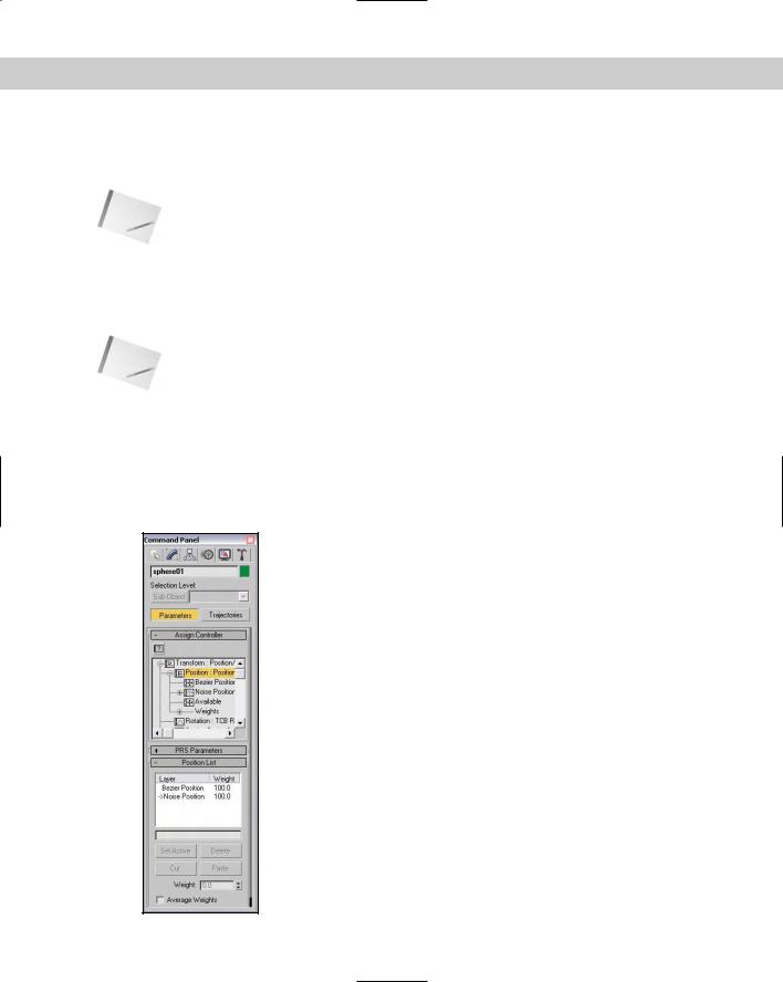
For example, Figure 31-7 shows the Motion panel for a sphere object that has the default Position XYZ controller assigned to the Position track. If you choose Animation Position Controllers Noise, then the Position List controller is added to the Position track, of which the Position XYZ and Noise controller are two available controllers.
Figure 31-7: The Motion panel displays all transform controllers applied to an object.
780 Part VII Animation
The List controller allows you to set Weights for each of its controllers. Using the Position List rollout, you can set the active controller and delete controllers from the list. You can also Cut and Paste controllers to other tracks.
Assigning controllers in the Motion panel
The top of the Motion panel includes two buttons: Parameters and Trajectories. Clicking the Parameters button makes the Assign Controller rollout available.
To change a transformation track’s controller, select the track and click the Assign Controller button positioned directly above the list. An Assign Controller dialog box
opens that is specific to the track you selected.
Cross- |
For more about the Trajectories button, see Chapter 30, “Animation Basics.” |
Reference |
|
For example, Figure 31-8 shows the Assign Position Controller dialog box for selecting a controller for the Position track. The arrow mark (>) shows the current selected controller. At the bottom of the dialog box, the default controller type is listed. Select a new controller from the list, and click OK. This new controller now is listed in the track, and the controller’s rollouts appear beneath the Assign Controller rollout.
Figure 31-8: The Assign Position Controller dialog box lets you select a controller to assign.
Caution |
You can assign controllers to other parameters for materials and modifiers, but you can |
|
assign controllers to the transformation tracks only by using the Motion panel. All other con- |
|
trollers are assigned using the Track View. |
Assigning controllers in Track View
You can also use the Track View to assign controllers. To do this, locate and select the track to apply a controller to, and then click the Assign Controller button on the
Controllers toolbar, choose the Controller Assign (keyboard shortcut, C) menu command, or right-click on the track and select Assign Controller from the pop-up menu. An Assign Controller dialog box opens in which you can select the controller to use.
Cross- |
Chapter 33, “Working with the Track View,” covers the details of the Track View. |
Reference |
|
Chapter 31 Animating with Constraints and Controllers |
781 |
You can also use the Controller toolbar to copy and paste controllers between tracks, but you can paste controllers only to similar types of tracks. When you paste controllers, the Paste dialog box lets you choose to paste the controller as a copy or as an instance. Changing an instanced controller’s parameters changes the parameters for all instances. The Paste dialog box also includes an option to replace all instances. This option replaces all instances of the controller, whether or not they are selected.
Setting Default Controllers
When you assign controllers using the Track View, the Assign Controller dialog box includes the option Make Default. With this option, the selected controller becomes the default for the selected track.
You can also set the global default controller for each type of track by choosing Customize Preferences, selecting the Animation panel, and then clicking the Set Defaults button. The Set Controller Defaults dialog box opens, in which you can set the default parameter settings, such as the In and Out curves for the controller. To set the default controller, select a controller from the list and click the Set Defaults button to open a controller-specific dialog box where you can adjust the controller parameters. The Animation panel also includes a button to revert to the original settings.
Note |
Changing a default controller does not change any currently assigned controllers. |
Examining the Various Controllers
Now that you’ve learned how to assign a controller, let’s take a look at the available controllers. Max includes a vast assortment of controllers, and you can add more controllers as plug-ins.
Earlier in the chapter, I mentioned six specific controller types. These types define the type of data that the controller works with. This section covers the various controllers according to the types of tracks with which they work.
Note |
Looking at the function curves for a controller provides a good idea of how you can control it, |
|
so many of the figures that follow show the various function curves for the different controllers. |
Each of these controllers has a unique icon to represent it in the Track View. This makes them easy to identify.
Transform controllers
Multi-track transform controllers work with the Position, Rotation, and Scale tracks all at the same time. You access them by selecting the Transform track in the Motion panel and then clicking the Assign Controller button, or by choosing the Animation Transform Controllers menu command.
Position/Rotation/Scale Transform controller
The Position/Rotation/Scale Transform controller is the default controller for all transforms. This controller includes a Bézier controller for the Position and Scale tracks and
a Euler XYZ controller for the Rotation track.
782 Part VII Animation
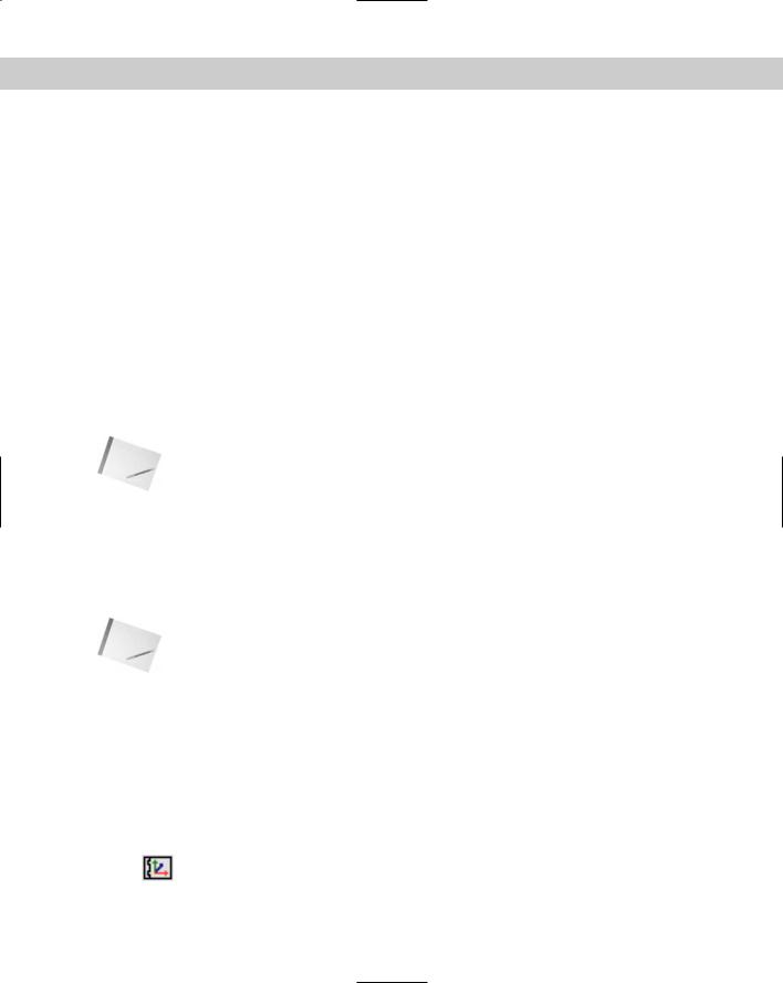
The PRS Parameters rollout, shown in Figure 31-9, lets you create and delete keys for Position, Rotation, and Scale transforms. The Position, Rotation, and Scale buttons control the fields that appear in the Key Info rollouts positioned below the PRS Parameters rollout.
Figure 31-9: The PRS Parameters rollout is the default transform controller.
Script controller
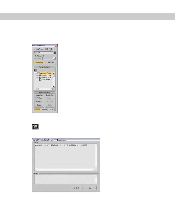
The Script controller is similar to the Expression controller, except that it can work with the MAXScript lines of code. Right-clicking a track with the Script controller assigned and
selecting Properties opens the Script Controller dialog box, shown in Figure 31-10.
Figure 31-10: The Script Controller dialog box runs scripts to generate animation keys.
Chapter 31 Animating with Constraints and Controllers |
783 |
This dialog box includes a Script pane and a Result pane. After a script loads, click the Evaluate button to execute the script.
Cross- |
For more information on MAXScript, see Chapter 48, “Automating with MAXScript.” |
Reference |
|
Position track controllers
Position track controller types include some of the common default controllers and can be assigned to the Position track. They typically work with three unique values representing the X, Y, and Z axes. These controllers can be assigned from the Animation Position Controllers menu. Many of the controllers found in this menu are also found in the Rotation and Scale Controllers menu.
Audio controller
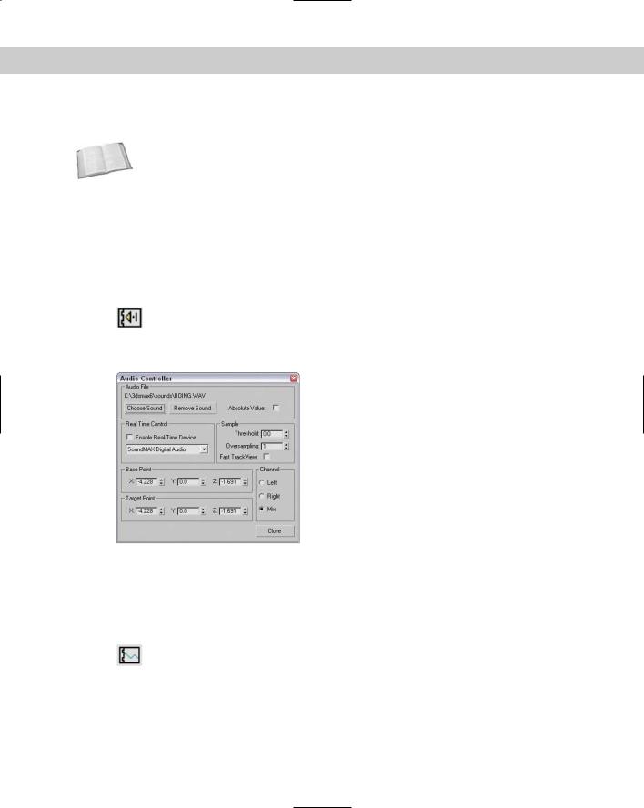
The Audio controller can control an object’s transform, color, or parameter value in response to the amplitude of a sound file. The Audio Controller dialog box, shown in
Figure 31-11, includes Choose Sound and Remove Sound buttons for loading or removing sound files.
Figure 31-11: The Audio Controller dialog box lets you change values based on the amplitude of a sound file.
The Real Time Control drop-down list lets you specify a device to control the system. To control the sound input, you can specify a Sample Threshold and Oversampling rate. You can also set Base Point and Target Point values for each axis. The Channel options let you specify which channel to use: Left, Right, or Mix.
Bézier controller
The Bézier controller is the default controller for many parameters. It enables you to interpolate between values using an adjustable Bézier spline. By dragging its tangent vertex handles, you can control the spline’s curvature. Tangent handles produce a smooth
transition when they lie on the same line, or you can create an angle between them for a sharp point. Figure 31-12 shows the Bézier controller assigned to a Position track.
784 Part VII Animation
Figure 31-12: The Bézier controller produces smooth animation curves.
The Bézier controller parameters are displayed in the Motion panel under two rollouts: Key Info (Basic) and Key Info (Advanced).
At the top of the Key Info (Basic) rollout are two arrows and a field that shows the key number. The arrows let you move between the Previous and Next keys. Each vertex shown in the function curve represents a key. The Time field displays the frame number where the key is located. The Time Lock button next to the Time field can be set to prevent the key from being dragged in Track View. The value fields show the values for the selected track; the number of fields changes depending on the type of track that is selected.
At the bottom of the Key Info (Basic) rollout are two flyout buttons for specifying the In and Out curves for the key. The arrows to the sides of these buttons move between the various In/Out curve types. The curve types include Smooth, Linear, Step, Slow, Fast, Custom, and Tangent Copy.
Cross- |
Chapter 33, “Working with the Track View,” describes these various In/Out curve types. |
Reference |
|
The In and Out values in the Key Info (Advanced) rollout are enabled only when the Custom curve type is selected. These fields let you define the rate applied to each axis of the curve. The Lock button changes the two values by equal and opposite amounts. The Normalize Time button averages the positions of all keys. The Constant Velocity option interpolates the key between its neighboring keys to provide smoother motion.
Expression controller
The Expression controller can define a mathematical expression that controls the track values. These expressions can use the values of other tracks and basic mathe-
matical functions such as sines and logarithms to control animation keys.
Cross- |
Chapter 32, “Using the Expression Controller,” covers the Expression controller. |
Reference |
|
Chapter 31 Animating with Constraints and Controllers |
785 |
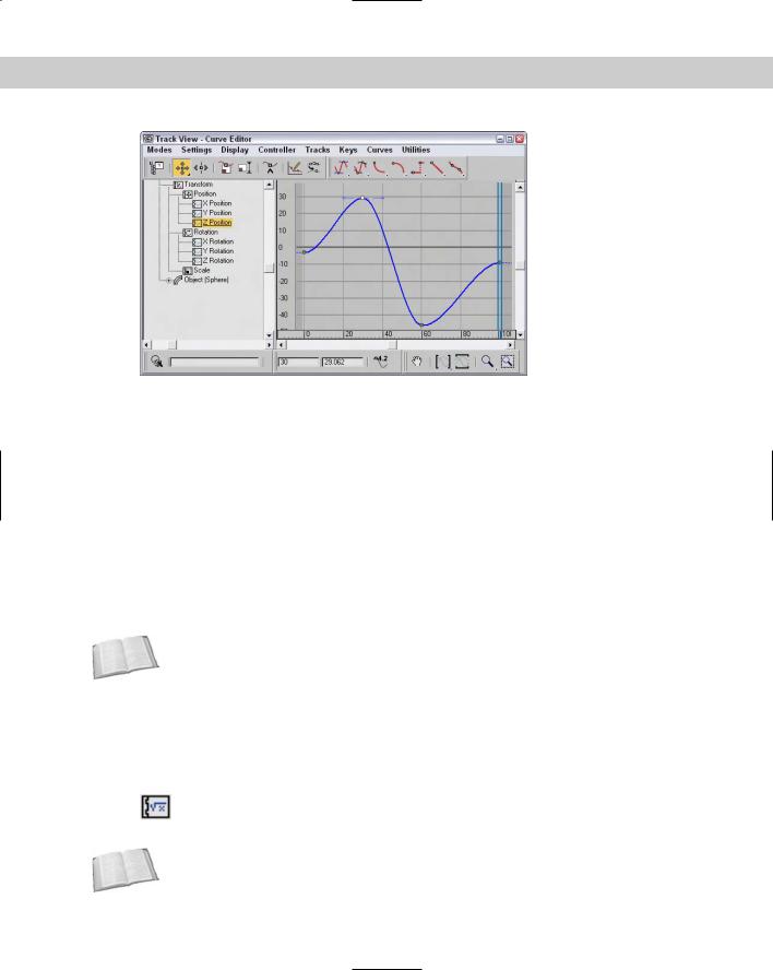
Linear controller
The Linear controller interpolates between two values to create a straight line.
The Linear controller doesn’t include any parameters and can be applied to time or values. Figure 31-13 shows the curves from the previous example after the Linear controller is assigned — all curves have been replaced with straight lines.
Figure 31-13: The Linear controller uses straight lines.
Motion Capture controller
The Motion Capture controller allows you to control an object’s transforms using an external device such as a mouse, keyboard, joystick, or MIDI device. This controller
works with the Motion Capture utility to capture motion data.
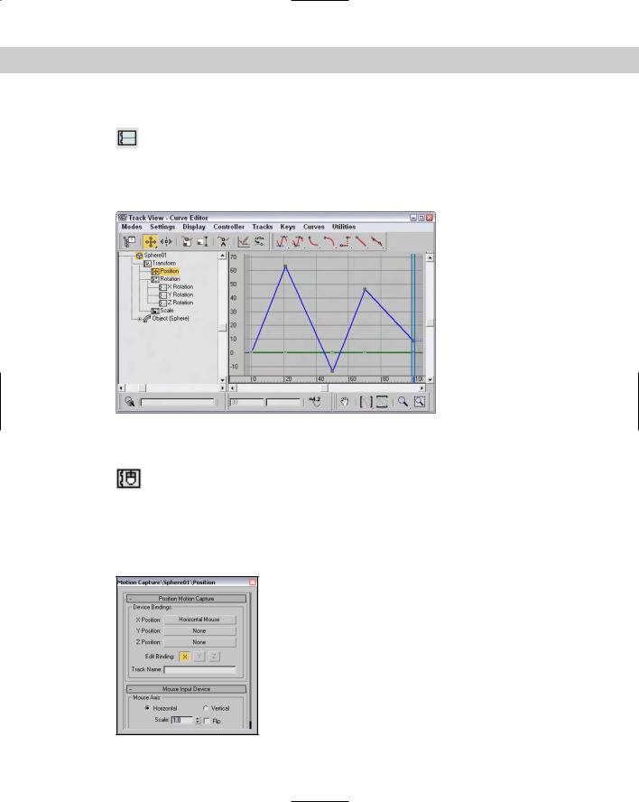
After you assign the Motion Capture controller to a track, right-click the track and select Properties from the pop-up menu to open the Motion Capture panel, shown in Figure 31-14. This dialog box lets you select the devices to use to control the motion of the track values. Options include Keyboard, Mouse, Joystick, and MIDI devices.
Figure 31-14: The Motion Capture controller lets you control track values using external devices.

786 Part VII Animation
For the Keyboard control, the Keyboard Input Device rollout appears, as shown in Figure 31-15. The Assign button lets you select a keyboard key to track. The other settings control the Envelope Graph, which defines how quickly key presses are tracked.
Figure 31-15: The Keyboard Input Device rollout lets you select which key press is captured.
The Motion Capture dialog box defines only which device controls which values. The actual capturing of data is accomplished using the Motion Capture utility. Selecting the Motion Capture utility in the Utility panel displays the Motion Capture rollout. This rollout includes buttons to Start, Stop, and Test the data-capturing process.
Before you can use the Start, Stop, and Test buttons, you need to select the tracks to capture from the Tracks list. The Record Range section lets you set the Preroll, In, and Out values, which are the frame numbers to include. You can also set the number of Samples Per Frame. The Reduce Keys option removes any unnecessary keys, if enabled.
Tutorial: Drawing with a pencil with the Motion Capture controller
Some motions, such as drawing with a pencil, are natural motions for our hands, but they become very difficult when you’re trying to animate using keyframes. This tutorial uses the Motion Capture controller and utility to animate the natural motion of drawing with a pencil.
To animate a pencil drawing on paper, follow these steps:
1.Open the Drawing with a pencil.max file from the Chap 31 directory on the CD-ROM. This file has a pencil object positioned on a piece of paper.
2.Select the pencil object, open the Motion panel, and select the Position track for the pencil object. Then click the Assign Controller button, and double-click the Position Motion Capture selection.
The Motion Capture dialog box opens.
3.Click the X Position button, and double-click the Mouse Input Device selection. Then click the Y Position button, and double-click the Mouse Input Device selection again. In the Mouse Input Device rollout, select the Vertical option. This sets the X Position to the Horizontal Mouse movement and the Y Position to the Vertical Mouse movement. Close the Motion Capture dialog box.
Chapter 31 Animating with Constraints and Controllers |
787 |
4.Open the Utilities panel, and click the Motion Capture button. In the Motion Capture rollout, select the Position track, and get the mouse ready to move. Then click the Start button in the Record Controls section, and move the mouse as if you were drawing with the mouse. The pencil object moves in the viewport along with your mouse movements.
The Motion Capture utility creates a key for each frame. It quits capturing the motion when it reaches frame 100.
5.Click the Play Animation button (or press the / key) to see the results.
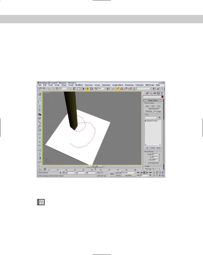
Figure 31-16 shows the scene after the Motion Capture controller has computed all the frames.
Figure 31-16: The Motion Capture controller and utility let you animate with the mouse, keyboard, joystick, or a MIDI device.
Noise controller
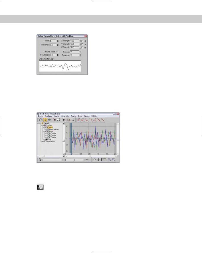
The Noise controller applies random variations in a track’s values. In the Noise Controller dialog box, shown in Figure 31-17, the Seed value determines the randomness of
the noise, and the Frequency value determines how jagged the noise is. You can also set the Strength along each axis: The > (greater than) 0 option for each axis makes the noise values remain positive.
788 Part VII Animation
Figure 31-17: The Noise controller properties let you set the noise strength for each axis.
There is also an option to enable Fractal Noise with a Roughness setting.
The Ramp in and Ramp out values determine the length of time before or until the noise can reach full value. The Characteristic Graph gives a visual look at the noise over the range. Figure 31-18 shows the Noise controller assigned to the Position track. If you need to change any Noise properties, right-click on the Noise track and select Properties from the pop-up menu.
Figure 31-18: The Noise controller lets you randomly alter track values.
Quaternion (TCB) controller
The Quaternion (TCB) controller produces curved animation paths similar to the Bézier controller, but it uses the values for Tension, Continuity, and Bias to define their
curvature.
The parameters for this controller are displayed in a single Key Info rollout. Like the Bézier controller rollouts, the Quarternion (TCB) controller rollout includes arrows and Key, Time, and Value fields. It also includes a graph of the TCB values; the red plus sign represents the current key’s position, while the rest of the graph shows the regular increments of time as black plus signs. Changing the Tension, Continuity, and Bias values in the fields below the graph changes its shape. Right-clicking the track and selecting Properties from the pop-up menu opens the TCB graph dialog box, shown in Figure 31-19.
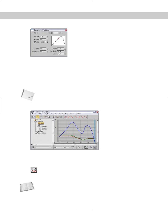
Chapter 31 Animating with Constraints and Controllers |
789 |
Figure 31-19: This dialog box shows and lets you control a curve defined by the Tension, Continuity, and Bias values.
The Tension value controls the amount of curvature: High Tension values produce a straight line leading into and away from the key, and low Tension values produce a round curve. The Continuity value controls how continuous, or smooth, the curve is around the key: The default value of 25 produces the smoothest curves, whereas high and low Continuity values produce sharp peaks from the top or bottom. The Bias value controls how the curve comes into and leaves the key point: High Bias values cause a bump to the right of the key, and low Bias values cause a bump to the left.
The Ease To and Ease From values control how quickly the key is approached or left.
Note |
Enabling the trajectory path by clicking the Trajectory button in the Motion panel lets you see |
|
the changes to the path as they are made in the Key Info rollout. |
Figure 31-20 shows three TCB curves assigned to the Position track of an object.
Figure 31-20: The TCB controller offers a different way to work with curves.
Reactor controller
The Reactor controller changes its values as a reaction to another controller. This controller is different from the Attachment controller in that the motions don’t need to be
in the same direction. For example, you can have one object rise as another object moves to the side.
Cross- |
Don’t confuse the Reactor controller with the reactor plug-in, which computes motion based |
Reference |
on physical dynamics. The reactor plug-in is covered in Chapter 40, “Animating with reactor.” |
|
790 Part VII Animation
After the Reactor controller is assigned to a track, you can define the reactions using the Reactor Parameters dialog box, shown in Figure 31-21. Selecting and right-clicking the track with this controller assigned and selecting Properties from the pop-up menu opens this dialog box.
The React To button lets you select an object in one of the viewports. After selecting a React To object, a pop-up dialog box appears, letting you select a transform parameter. To add a reaction to the list, click the Create Reaction button. The Delete Reaction button deletes the selected reaction from the list. The Set Reaction Value button lets you specify the value for the reaction. These values are displayed in the Reaction Value field. Each reaction can have an Influence, Strength, and Falloff value.
Figure 31-21: The Reactor Parameters dialog box lets you set the parameters of a reaction.
Tutorial: Rotating gears with the reactor controller
Many mechanical devices use gears, and animating these gears can be tricky because every adjacent gear rotates in the opposite direction. Animating by linking the gears together causes one gear to rotate around the other one. You can achieve this motion by animating the rotation of every gear individually, or you can use the Reactor controller to make the gears work like they are supposed to — which is what we do in this tutorial.
To rotate gears using the Reactor controller, follow these steps:
1.Open the Reactor rotating gears.max file from the Chap 31 directory on the CD-ROM. This file contains some gears created using the Ringwave primitive.
2.Select the first gear, click the Auto Key button (or press the N key), and drag the Time Slider to frame 100 (or press the End key). Then select the Select and Rotate button (or press the E key), and right-click it to open the Rotate Transform Type-In. Enter a value of 180 in the Z-axis field.
3.Open the Track View, and locate the Rotation track for the second gear. Select this track, and click the Assign Controller button. Select the Rotation Reactor option, and click OK.
The Reactor Parameters dialog box opens.

Chapter 31 Animating with Constraints and Controllers |
791 |
4.Drag the Time Slider back to frame 0 (or press the Home key). Click the React To button, select the first gear object, and choose Transform Rotation track from the pop-up menu.
A reaction called Reaction01 is created in the list.
5.Drag the Time Slider to frame 100 (or press the End key), and click the Create Reaction button. This creates another reaction called Reaction02 in the list. Click the Edit Reaction State button to enable it. Then select the second gear, select and right-click the Select and Rotate button on the main toolbar, and enter –180 in the World Z-axis Offset. Click again on the Edit Reaction State button to disable it.
6.Click the Play Animation button (or press the / key) to see the gears move together.
Figure 31-22 shows the two gears and the Reactor Parameters dialog box. The second gear rotates in the opposite direction of the first gear.
Spring controller
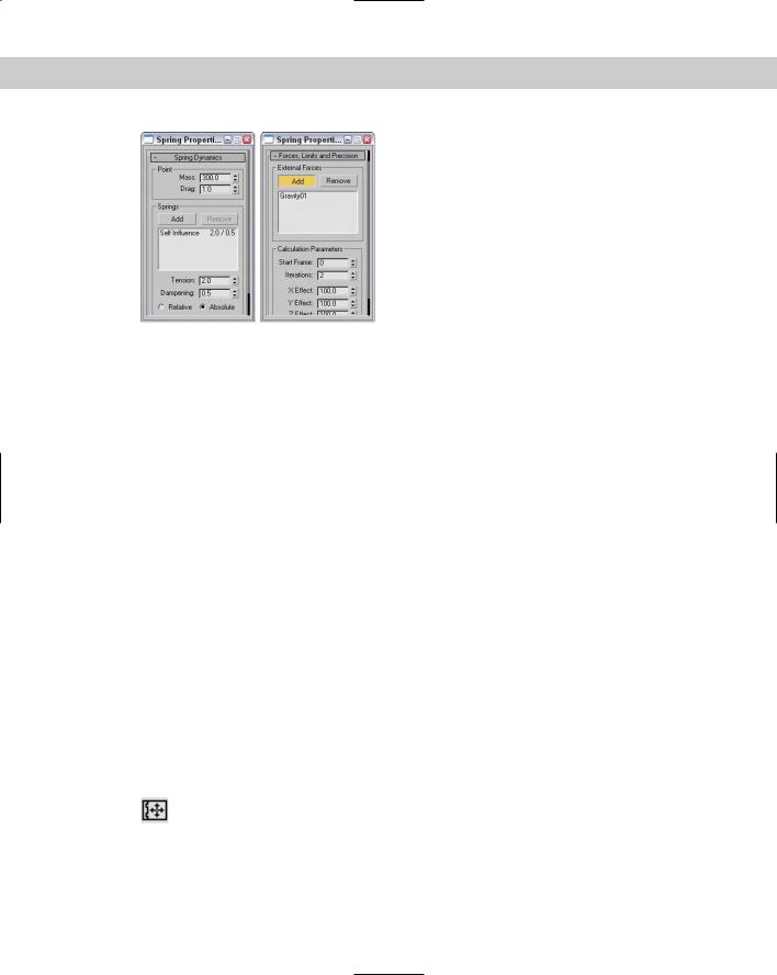
The Spring controller is similar in many ways to the Flex modifier in that it adds secondary motion associated with the wiggle of a spring after a force has been applied and
then removed. When the Spring controller is applied, a panel with two rollouts appears. These rollouts, shown in Figure 31-23, let you control the physical properties of the spring and the forces that influence it.
Figure 31-22: The Reactor controller animates these two opposite rotating gears.
792 Part VII Animation
Figure 31-23: The Spring controller rollouts can add additional springs and forces.
In the Spring Dynamics rollout, you can change the Mass and Drag values. Higher mass values result in greater secondary motion as the object is moved, and the Drag value controls how quickly the bouncing motion stops. You can add multiple springs, each with its own Tension and Damping values to be applied Relative or Absolute.
The Forces, Limits, and Precision rollout lets you add forces that impact the spring motion. The Add button lets you identify these forces, which are typically Space Warps, and you can limit the effect to specific axes.
Tutorial: Wagging a tail with the Spring controller
One of the best uses of the Spring controller is to gain the secondary motion associated with an existing motion. For example, if a character moves, then appendages such as a tail can easily follow if you apply a Spring controller to it.
To wag a row of spheres using the Spring controller, follow these steps:
1.Open the Dog wagging tail.max file from the Chap 31 directory on the CD-ROM.
This file contains a linked row of spheres with the head sphere animated rotating back and forth.
2.Select the smallest sphere, and choose the Animation Position Controllers Spring menu command. This moves the sphere to its parent. Choose the Select and Move button (or press the W key), and return the sphere to its original position.
3.Repeat Step 2 for the remaining spheres, moving from smallest to largest.
4.Click the Play Animation button (or press the / key) to see the resulting motion.
Figure 31-24 shows a frame the final motion. Notice that the spheres aren’t lined up exactly. The smallest sphere is moving the greatest distance because all the springs are adding their effect.
Position XYZ controller
The Position XYZ controller splits position transforms into three separate tracks, one for each axis. Each axis has a Bézier controller applied to it, but each component track
can be assigned a different controller. The Position XYZ Parameters rollout lets you switch between the component axes.
The Rotation tracks use a variety of controllers, many of them common to the Position track. This section lists the controllers that can be used only with the Rotation track.

Chapter 31 Animating with Constraints and Controllers |
793 |
Figure 31-24: The Spring controller adds secondary motion to the existing motion of the largest sphere.
Rotation and Scale track controllers
The Rotation and Scale track controller types include some of the common default controllers and can be assigned to the Rotation and Scale tracks. They typically work with three unique values representing the X, Y, and Z axes. These controllers can be assigned from the Animation Rotation (Scale) Controllers menu. Many of the controllers found in this menu are also found in the Position Controllers menu. Only the controllers unique to the Rotation and Scale tracks are covered here.
Euler XYZ Rotation controller
The Euler XYZ Rotation controller lets you control the rotation angle along the X, Y, and Z axes based on a single float value for each frame. Euler rotation is different from
Max’s default rotation method (which is quaternion rotation and not as smooth).
The main difference is that Euler rotation gives you access to the function curves. Using these curves, you can smoothly define the rotation motion of the object.
Note |
Euler XYZ Rotation values are in radians instead of degrees. Radians are much smaller values |
|
than degrees. A full revolution is 360 degrees or 2 times Pi radians, so one degree equals |
|
about 0.0174 radians. |
The Euler Parameters rollout lets you choose the Axis Order, which is the order in which the axes are calculated. You can also choose which axis to work with.
794 Part VII Animation
Smooth Rotation controller
The Smooth Rotation controller automatically produces a smooth rotation. This controller doesn’t add any new keys; it simply changes the timing of the existing keys to
produce a smooth rotation. It does not have any parameters.
Scale XYZ controller
Max has one controller that you can use only in Scale tracks. The Scale XYZ controller breaks scale transforms into three separate tracks, one for each axis. This feature enables
you to precisely control the scaling of an object along separate axes. It is a better alternative to using Select and Non-Uniform Scale from the main toolbar because it is independent of the object geometry.
The Scale XYZ Parameters rollout lets you select which axis to work with. This controller works the same way as the other position and rotation XYZ controllers.
Parameter controllers
Other types of controllers consist of miscellaneous collections that don’t fit into the previous categories. Many of these controllers combine several controllers into one, such as the List and Block controllers. Others include separate interfaces, such as the Waveform controller for defining the controller’s functions.
Most of these special-purpose controllers can be assigned only by using the Track View window. The Motion panel contains only the tracks for transformations.
On/Off controller
The On/Off controller works on tracks that hold a binary value, such as the Visibility track; you can use it to turn the track on and off or to enable and disable options. In the Track View, each On section is displayed in blue, with keys alternating between on and
off. No parameters exist for this controller. Figure 31-25 shows a Visibility track that has been added to a sphere object. This track was added using the Tracks Visibility Track Add menu command. You can add keys with the Add Keys button. Each new key toggles the track on and off.
Note |
You can also add a Visibility track by changing the Visibility value in the Object Properties dia- |
|
log box. |
Boolean controller
The Boolean controller, like the On/Off controller, can hold one of two states: 0 for off and 1 for on. But, unlike the On/Off controller, the Boolean controller changes only
when a different state is encountered.
Waveform controller
The Waveform controller can produce regular periodic waveforms, such as a sinusoidal wave. Several different waveform types can make up a complete waveform. The Wave-
form Controller dialog box, shown in Figure 31-26, includes a list of all the combined waveforms. To add a waveform to this list, click the Add button.

Chapter 31 Animating with Constraints and Controllers |
795 |
Figure 31-25: The On/Off controller lets you make objects appear and disappear.
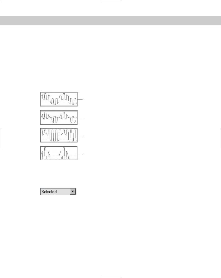
When you select a waveform in the list, you can give it a name and edit its shape using the buttons and values. Preset waveform shapes include Sine, Square, Triangle, Sawtooth, and Half Sine. You can also invert and flip these shapes.
Triangle
Square Sawtooth
Sine |
Half Sine |
Figure 31-26: The Waveform Controller dialog box lets you produce sinusoidal motions.
The Period value defines the number of frames required to complete one full pattern. The Amplitude value sets the height of the wave, and the Phase value determines its location at the start of the cycle. The Duty Cycle value is used only for the square wave to define how long it stays enabled.
796 Part VII Animation
You can use the Vertical Bias options to set the values range for the waveform. Options include Centered, which sets the center of the waveform at 0; Auto > 0, which causes all values to be positive; Auto < 0, which causes all values to be negative; and Manual, which lets you set a value for the center of the waveform.
The Effect option determines how different waveforms in the list are combined. They can be added, multiplied, clamped above, or clamped below. The Add option simply adds the waveform values together, and the Multiply option multiplies the separate values. The Clamp Above or Clamp Below option forces the values of one curve to its maximum or minimum while not exceeding the values of the other curve. The Characteristic Graph shows the selected waveform, the output, or the final resulting curve. Figure 31-27 shows the Characteristic Graph for each Effect option when a sine wave and a square wave are combined.
Addition
Multiplication
Clamped Above
Clamped Below
Figure 31-27: Combining sine and square waves with the Add, Multiply, Clamp Above, and Clamp Below Effect options.
Color RGB controller
You can use the Color RGB controller to animate colors. Color values are different from regular float values in that they include three values
that represent the amounts of red, green, and blue (referred to as RGB values) that are present in the color. This data value type is known as Point3.
The Color RGB controller splits a track with color information into its component RGB tracks. You can use this controller to apply a different controller to each color component and also to animate any color swatch in Max.
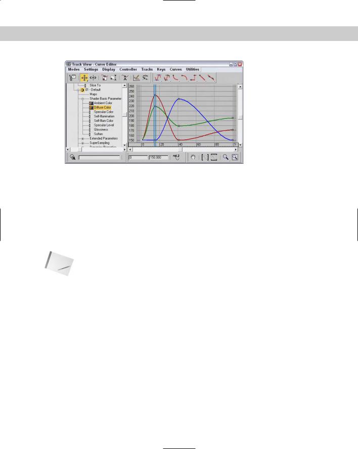
Figure 31-28 shows the function curves for the Color RGB controller assigned to the Diffuse Color track under the Material #1 track, including subtracks for Red, Green, and Blue. The figure shows the Bézier controller applied to the Red track, the Noise controller that is assigned to the Green track, and the Waveform controller with a triangle wave applied to the Blue track.
Chapter 31 Animating with Constraints and Controllers |
797 |
Figure 31-28: The Color RGB controller lets you assign different controllers to each color component.
Cubic Morph controller
You can assign the Cubic Morph controller to a morph compound object. You can find the track for this object under the Objects track. A subtrack of the morph object is the Morph track, which holds the morph keys.
The Cubic Morph controller uses Tension, Continuity, and Bias values to control how targets blend with one another. You can access these TCB values in the Key Info dialog box by rightclicking any morph key or by right-clicking the Morph track and selecting Properties from the pop-up menu.
Note |
You can also access the TCB values by right-clicking the keys in the Track Bar. |
Barycentric Morph controller
The Barycentric Morph controller is automatically applied when a morph compound object is created. Keys are created for this controller based on the morph targets set in the Modify panel under the Current Targets rollout for the morph compound object. You can edit these keys using the Barycentric controller Key Info dialog box, which you can open by right-clicking a morph key in the Track View or in the Track Bar.
The main difference between the Cubic Morph controller and the Barycentric Morph controller is that the latter can have weights applied to the various morph keys.
The Barycentric Morph controller Key Info dialog box includes a list of morph targets. If a target is selected, its Percentage value sets the influence of the target. The Time value is the frame where this key is located. The TCB values and displayed curve control the Tension, Continuity, and Bias parameters for this controller. The Constrain to 100% option causes all weights to equal 100 percent; changing one value changes the other values proportionally if this option is selected.

798 Part VII Animation
List controller
You can use the List controller to apply several controllers at once. This feature enables you to produce smaller, subtler deviations, such as adding some noise to a
normal Path controller.
When the List controller is applied, the default track appears as a subtrack along with another subtrack labeled Available. By selecting the Available subtrack and clicking the Assign Controller button, you can assign additional controllers to the current track.
All subtrack controllers are included in the List rollout of the Motion panel. You can also access this list by right-clicking the track and selecting Properties from the pop-up menu. The order of the list is important, because it defines which controllers are computed first.
The Set Active button lets you specify which controller you can interactively control in the viewport; the active controller is marked with an arrow, which is displayed to the left of the name. You can also cut and paste controllers from and to the list. Because you can use the same controller type multiple times, you can distinguish each one by entering a name in the Name field.
Block controller
The Block controller combines several tracks into one block so you can handle them all together. This controller is located in the Global Tracks track. If a track is added to a
Block controller, a Slave controller is placed in the track’s original location.
To add a Block controller, select the Available track under the Block Control track under the Global Tracks track, and click the Assign Controller button. From the Assign Constant Controller dialog box that opens, select Master Block (Master Block is the only selection) and click OK. Right-click the Master Block track to open the Master Block Parameters dialog box, shown in Figure 31-29.
Figure 31-29: The Master Block Parameters dialog box lists all the tracks applied to a Block controller.
In the Master Block Parameters dialog box, you can add a track to the Block controller with the Add button. All tracks added are displayed in the list on the left. You can give each track a name by using the Name field. You can also use the Add Selected button to add any selected tracks. The Replace button lets you select a new controller to replace the currently selected track. The Load and Save buttons enable you to load or save blocks as separate files.
Chapter 31 Animating with Constraints and Controllers |
799 |
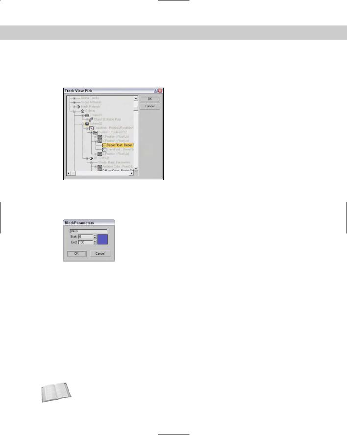
The Add button opens the Track View Pick dialog box, shown in Figure 31-30. This dialog box displays all valid tracks in a darker color to make them easier to see, while graying out invalid tracks.
Figure 31-30: The Track View Pick dialog box lets you select the tracks you want to include in the Block controller.
Select the tracks that you want to include, and click the OK button. This Block Parameters dialog box opens, shown in Figure 31-31, in which you can name the block, specify Start and End frames, and choose a color. Click OK when you’ve finished with this dialog box.
Figure 31-31: The Block Parameters dialog box lets you name a block.
Back in the Master Block Parameters dialog box, click the Load button to open a file dialog box where you can load a saved block of animation parameters. The saved block files have the .BLK extension. After the parameters have loaded, the Attach Controls dialog box opens, as shown in Figure 31-32. This dialog box includes two panes. The Incoming Controls pane on the left lists all motions in the saved block. By clicking the Add button, you can add tracks from the current scene, to which you can copy the saved block motions.
Because the saved motions in the Incoming Controls pane will match up with the Copy to entries in the right pane, the Add Null button adds a space in place of a specific track if you don’t want a motion to be copied. The Match by Node button matches tracks by means of the Track View Pick dialog box.
IK controller
The IK controller works on a bones system for controlling the bone objects of an IK system. The IK controller includes many different rollouts for defining joint constraints and other parameters.
Cross- |
Find out more about the IK controller in Chapter 37, “Using Inverse Kinematics.” |
Reference |
|
800 Part VII Animation
Figure 31-32: The Attach Controls dialog box lets you attach saved tracks to the Block controller.
Master Point controller
The Master Point controller controls the transforms of any point or vertex subobject selections. The Master Point controller gets added as a track to an object whose sub-
objects are transformed. Subtracks under this track are listed for each subobject. The keys in the Master track are colored green.
Right-clicking a green master key opens the Master Track Key Info dialog box, shown in Figure 31-33. This dialog box shows the Key number with arrows for selecting the previous or next key, a Time field that displays the current frame number, and a list of all the vertices. Selecting a vertex from the list displays its parameters at the bottom of the dialog box.
Figure 31-33: The Master Track Key Info dialog box lets you change the key values for each vertex.
Figure 31-34 shows the Master Point controller that was automatically assigned when a selection of vertex subobjects was moved with the Auto Key button enabled. A separate track is created for each vertex.