

258 Part II Working with Objects
7.Select all the planet nodes, and choose Layout Align Top to align all the nodes together.
Figure 9-5 shows the rearranged hierarchy with all the planets lined up in order.
Figure 9-5: After rearranging nodes to the correct order, the planets are easy to locate.
Working with Hierarchies
Another key benefit of the Schematic View is to see the relationships between different objects. With the Schematic View open, you can quickly tell which objects are children and which are parents. You can also see which objects have modifiers and which have materials applied. You can get a wealth of knowledge from the Schematic View.
Using the Display floater
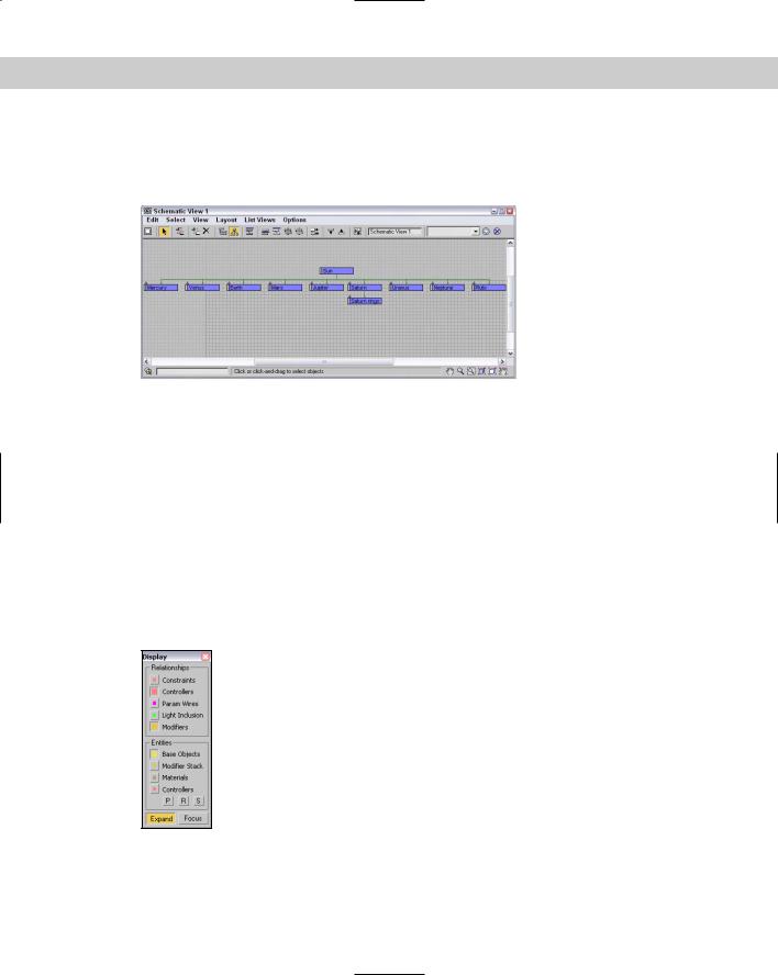
With all relationships enabled, the Schematic View becomes a mess. Luckily, you can control which Relationships and which Entities are displayed using the Display floater, shown in Figure 9-6.
Figure 9-6: The Display floater can turn nodes and lines on and off in the
Schematic View.
Chapter 9 Working with the Schematic View 259
|
The top section of the Display floater shows or hides relationships between nodes, which are |
|
displayed as lines. The relationships that you can control include Constraints, Controllers, |
|
Param Wires, Light Inclusion, and Modifiers. If you hold the mouse over these relationship |
|
lines, the details of the relationship are shown in the tooltip that appears. |
Tip |
For some relationships, you can double-click on the relationship line to open a dialog box |
|
where you can edit the relationship. For example, double-clicking on a Parameter Wire rela- |
|
tionship line opens the Parameter Wiring dialog box. |
|
The lower section lets you show or hide entities that are displayed as nodes, including Base |
|
Objects, Modifier Stack, Materials, and Controllers. The P, R, and S buttons let you turn on |
|
Positional, Rotational, and Scale controllers. When a node has a relationship with another |
|
node, the right end of the node displays an arrow. Clicking this arrow toggles the relationship |
|
lines on and off. |
|
The Expand button shows the actual nodes when enabled, but only an arrow that can be |
|
clicked on to access the nodes if disabled. The Focus button shows all related objects as |
|
colored nodes and all other nodes are unshaded. |
|
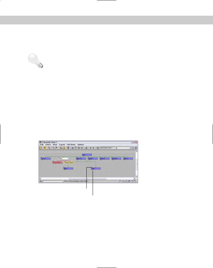
Figure 9-7 shows a Schematic View with the Base Objects and Controllers Entities selected |
|
in the Display floater. The Expand button is also disabled. This makes up and down arrows |
|
appear above each node. Clicking the up arrow collapses the node, rolling it up into its parent. |
|
Clicking the down arrow expands the node and displays the Base Object and Controller nodes |
|
for the node that you clicked on, such as the Earth node in Figure 9-7. You can also expand and |
|
collapse nodes with the Layout Expand Selected and Collapse Selected menu commands. |
Collapse (up) arrow
Expand (down) arrow
Figure 9-7: Schematic View nodes can be collapsed or expanded by clicking the up and down arrows.
Hierarchical relationships are shown as lines that connect the nodes. Even if the nodes are moved, the lines follow as needed to show the relationship between the nodes.
260 Part II Working with Objects
Connecting nodes
To create a hierarchy, use the Edit Connect (C) menu command or click the Connect button on the Schematic View toolbar. This enters Connect mode, which lets you link objects together; copy modifiers, materials, or controllers between nodes; or even wire parameters.
For linking nodes, the Connect button works the same way here as it does on the main toolbar — selecting the child node and dragging a line from the child node to its parent. You can even select multiple nodes and link them all at once.
The Edit Unlink Selected menu command (and toolbar button) destroys the link between any object and its immediate parent. Remember that every child object can have only one parent.
Copying modifiers and materials between nodes
Before you can copy materials or modifiers between nodes, you need to make sure that they are visible. Materials and modifiers nodes show up only if they are enabled in the Display floater. You can access this floater by clicking the Display floater button (or by pressing the D key).
To copy a material or modifier, select the material node for one object, click the Connect (C) button, and drag the material to another object node.
Note |
In the Schematic View, materials can be copied only between objects — you cannot apply |
|
new materials from the Material Editor to Schematic View nodes. |
When modifiers are copied between nodes, a dialog box appears giving you the chance to Copy, Move, or Instance the modifier. You can also use the Schematic View window to reorder the Modifier Stack. Using the Connect tool, just drag the modifier node to the modifier node that you want to be beneath and the stack is reordered.
Assigning controllers and wiring parameters
If controller nodes are visible, you can copy them to another node using the same technique used for materials and modifiers using the Connect (C) button. You can also assign a controller to an object node that doesn’t have a controller using the Edit Assign Controller menu command. This opens the Assign Controller dialog box, shown in Figure 9-8, where you can select the controller to apply.
Figure 9-8: Controllers can be assigned using the
Schematic View window.

Chapter 9 Working with the Schematic View 261
Nodes can be wired using the Schematic View window. To wire parameters, just select the node that you want to wire and select Edit Wire Parameters. A pop-up menu of wire parameters appears that works the same as in the viewports. All parameter wiring relationships are shown in magenta.
Cross- |
You can learn more about parameter wiring in Chapter 30, “Animation Basics.” |
Reference |
|
Tutorial: Linking a character with Schematic View
Perhaps one of the greatest benefits of the Schematic View is its ability to link objects. This can be tricky in the viewports because some objects are small and hidden behind other items. The Schematic View with its nodes that are all the same size makes it easy, but only if the objects are named correctly.
To link a character model using the Schematic View, follow these steps:
1.Open the Futuristic man.max file from the Chap 09 directory on the CD-ROM.
This file includes a simplified version of a futuristic man created by Viewpoint Datalabs with no links between the various parts.
2.Select Graph Editors New Schematic View to open a Schematic View window and name the view Linked character. Click the Region Zoom button in the lower-right corner, and drag over the nodes at the left end of the Schematic View.
For this model, we want the pelvis to be the parent node.
3.Click the Connect button on the toolbar (or press the C key), and drag from the handr node to the armr node to link the two nodes. Continue linking by connecting the following nodes: handl to arml, head to neck, pupil to eyes, bootr to legr, bootl to legl, and torso to pelvis.
4.Select the eyes, mask, patch, and hair nodes, and drag them all to the head node.
5.Finally, grab the armr, arml, neck, and katana nodes, and drag them to the torso node and the legr and legl nodes to the pelvis node.
This completes the hierarchy.
Note Typically when rigging characters, you want the pelvis to be the parent object because it is the center of most of the character movement. In this example, the torso was easier to use because of its size.
Figure 9-9 shows the final geometry object nodes of the linked character. If you move the torso part in the viewports, all the parts move together.