

- •Preface
- •About This Book
- •Acknowledgments
- •Contents at a Glance
- •Contents
- •Relaxing at the Beach
- •Dressing the Scene
- •Animating Motion
- •Rendering the Final Animation
- •Summary
- •The Interface Elements
- •Using the Menus
- •Using the Toolbars
- •Using the Viewports
- •Using the Command Panel
- •Using the Lower Interface Bar Controls
- •Interacting with the Interface
- •Getting Help
- •Summary
- •Understanding 3D Space
- •Using the Viewport Navigation Controls
- •Configuring the Viewports
- •Working with Viewport Backgrounds
- •Summary
- •Working with Max Scene Files
- •Setting File Preferences
- •Importing and Exporting
- •Referencing External Objects
- •Using the File Utilities
- •Accessing File Information
- •Summary
- •Customizing Modify and Utility Panel Buttons
- •Working with Custom Interfaces
- •Configuring Paths
- •Selecting System Units
- •Setting Preferences
- •Summary
- •Creating Primitive Objects
- •Exploring the Primitive Object Types
- •Summary
- •Selecting Objects
- •Setting Object Properties
- •Hiding and Freezing Objects
- •Using Layers
- •Summary
- •Cloning Objects
- •Understanding Cloning Options
- •Mirroring Objects
- •Cloning over Time
- •Spacing Cloned Objects
- •Creating Arrays of Objects
- •Summary
- •Working with Groups
- •Building Assemblies
- •Building Links between Objects
- •Displaying Links and Hierarchies
- •Working with Linked Objects
- •Summary
- •Using the Schematic View Window
- •Working with Hierarchies
- •Setting Schematic View Preferences
- •Using List Views
- •Summary
- •Working with the Transformation Tools
- •Using Pivot Points
- •Using the Align Commands
- •Using Grids
- •Using Snap Options
- •Summary
- •Exploring the Modifier Stack
- •Exploring Modifier Types
- •Summary
- •Exploring the Modeling Types
- •Working with Subobjects
- •Modeling Helpers
- •Summary
- •Drawing in 2D
- •Editing Splines
- •Using Spline Modifiers
- •Summary
- •Creating Editable Mesh and Poly Objects
- •Editing Mesh Objects
- •Editing Poly Objects
- •Using Mesh Editing Modifiers
- •Summary
- •Introducing Patch Grids
- •Editing Patches
- •Using Modifiers on Patch Objects
- •Summary
- •Creating NURBS Curves and Surfaces
- •Editing NURBS
- •Working with NURBS
- •Summary
- •Morphing Objects
- •Creating Conform Objects
- •Creating a ShapeMerge Object
- •Creating a Terrain Object
- •Using the Mesher Object
- •Working with BlobMesh Objects
- •Creating a Scatter Object
- •Creating Connect Objects
- •Modeling with Boolean Objects
- •Creating a Loft Object
- •Summary
- •Understanding the Various Particle Systems
- •Creating a Particle System
- •Using the Spray and Snow Particle Systems
- •Using the Super Spray Particle System
- •Using the Blizzard Particle System
- •Using the PArray Particle System
- •Using the PCloud Particle System
- •Using Particle System Maps
- •Controlling Particles with Particle Flow
- •Summary
- •Understanding Material Properties
- •Working with the Material Editor
- •Using the Material/Map Browser
- •Using the Material/Map Navigator
- •Summary
- •Using the Standard Material
- •Using Shading Types
- •Accessing Other Parameters
- •Using External Tools
- •Summary
- •Using Compound Materials
- •Using Raytrace Materials
- •Using the Matte/Shadow Material
- •Using the DirectX 9 Shader
- •Applying Multiple Materials
- •Material Modifiers
- •Summary
- •Understanding Maps
- •Understanding Material Map Types
- •Using the Maps Rollout
- •Using the Map Path Utility
- •Using Map Instances
- •Summary
- •Mapping Modifiers
- •Using the Unwrap UVW modifier
- •Summary
- •Working with Cameras
- •Setting Camera Parameters
- •Summary
- •Using the Camera Tracker Utility
- •Summary
- •Using Multi-Pass Cameras
- •Creating Multi-Pass Camera Effects
- •Summary
- •Understanding the Basics of Lighting
- •Getting to Know the Light Types
- •Creating and Positioning Light Objects
- •Viewing a Scene from a Light
- •Altering Light Parameters
- •Working with Photometric Lights
- •Using the Sunlight and Daylight Systems
- •Using Volume Lights
- •Summary
- •Selecting Advanced Lighting
- •Using Local Advanced Lighting Settings
- •Tutorial: Excluding objects from light tracing
- •Summary
- •Understanding Radiosity
- •Using Local and Global Advanced Lighting Settings
- •Working with Advanced Lighting Materials
- •Using Lighting Analysis
- •Summary
- •Using the Time Controls
- •Working with Keys
- •Using the Track Bar
- •Viewing and Editing Key Values
- •Using the Motion Panel
- •Using Ghosting
- •Animating Objects
- •Working with Previews
- •Wiring Parameters
- •Animation Modifiers
- •Summary
- •Understanding Controller Types
- •Assigning Controllers
- •Setting Default Controllers
- •Examining the Various Controllers
- •Summary
- •Working with Expressions in Spinners
- •Understanding the Expression Controller Interface
- •Understanding Expression Elements
- •Using Expression Controllers
- •Summary
- •Learning the Track View Interface
- •Working with Keys
- •Editing Time
- •Editing Curves
- •Filtering Tracks
- •Working with Controllers
- •Synchronizing to a Sound Track
- •Summary
- •Understanding Your Character
- •Building Bodies
- •Summary
- •Building a Bones System
- •Using the Bone Tools
- •Using the Skin Modifier
- •Summary
- •Creating Characters
- •Working with Characters
- •Using Character Animation Techniques
- •Summary
- •Forward versus Inverse Kinematics
- •Creating an Inverse Kinematics System
- •Using the Various Inverse Kinematics Methods
- •Summary
- •Creating and Binding Space Warps
- •Understanding Space Warp Types
- •Combining Particle Systems with Space Warps
- •Summary
- •Understanding Dynamics
- •Using Dynamic Objects
- •Defining Dynamic Material Properties
- •Using Dynamic Space Warps
- •Using the Dynamics Utility
- •Using the Flex Modifier
- •Summary
- •Using reactor
- •Using reactor Collections
- •Creating reactor Objects
- •Calculating and Previewing a Simulation
- •Constraining Objects
- •reactor Troubleshooting
- •Summary
- •Understanding the Max Renderers
- •Previewing with ActiveShade
- •Render Parameters
- •Rendering Preferences
- •Creating VUE Files
- •Using the Rendered Frame Window
- •Using the RAM Player
- •Reviewing the Render Types
- •Using Command-Line Rendering
- •Creating Panoramic Images
- •Getting Printer Help
- •Creating an Environment
- •Summary
- •Creating Atmospheric Effects
- •Using the Fire Effect
- •Using the Fog Effect
- •Summary
- •Using Render Elements
- •Adding Render Effects
- •Creating Lens Effects
- •Using Other Render Effects
- •Summary
- •Using Raytrace Materials
- •Using a Raytrace Map
- •Enabling mental ray
- •Summary
- •Understanding Network Rendering
- •Network Requirements
- •Setting up a Network Rendering System
- •Starting the Network Rendering System
- •Configuring the Network Manager and Servers
- •Logging Errors
- •Using the Monitor
- •Setting up Batch Rendering
- •Summary
- •Compositing with Photoshop
- •Video Editing with Premiere
- •Video Compositing with After Effects
- •Introducing Combustion
- •Using Other Compositing Solutions
- •Summary
- •Completing Post-Production with the Video Post Interface
- •Working with Sequences
- •Adding and Editing Events
- •Working with Ranges
- •Working with Lens Effects Filters
- •Summary
- •What Is MAXScript?
- •MAXScript Tools
- •Setting MAXScript Preferences
- •Types of Scripts
- •Writing Your Own MAXScripts
- •Learning the Visual MAXScript Editor Interface
- •Laying Out a Rollout
- •Summary
- •Working with Plug-Ins
- •Locating Plug-Ins
- •Summary
- •Low-Res Modeling
- •Using Channels
- •Using Vertex Colors
- •Rendering to a Texture
- •Summary
- •Max and Architecture
- •Using AEC Objects
- •Using Architectural materials
- •Summary
- •Tutorial: Creating Icy Geometry with BlobMesh
- •Tutorial: Using Caustic Photons to Create a Disco Ball
- •Summary
- •mental ray Rendering System
- •Particle Flow
- •reactor 2.0
- •Schematic View
- •BlobMesh
- •Spline and Patch Features
- •Import and Export
- •Shell Modifier
- •Vertex Paint and Channel Info
- •Architectural Primitives and Materials
- •Minor Improvements
- •Choosing an Operating System
- •Hardware Requirements
- •Installing 3ds max 6
- •Authorizing the Software
- •Setting the Display Driver
- •Updating Max
- •Moving Max to Another Computer
- •Using Keyboard Shortcuts
- •Using the Hotkey Map
- •Main Interface Shortcuts
- •Dialog Box Shortcuts
- •Miscellaneous Shortcuts
- •System Requirements
- •Using the CDs with Windows
- •What’s on the CDs
- •Troubleshooting
- •Index

Character Modeling
Acharacter is any object in the scene that holds the focus. It is the main actor or star of the scene. Although characters are typ-
ically thought of as human or animal figures, they can actually be any type of object that is endowed with life.
Endowing a character with life happens during the animation process, but before you can animate a character, you want to take several steps that will make the job of animating much easier. Keeping these steps in mind as you build, rig, and prepare to animate a character will make a huge difference in how much life you can add to a character.
Modeling is key to 3d animation, and an entire part of the book focuses on modeling, but what is so special about character modeling that it deserves a whole chapter separate from the rest of the modeling chapters? Character modeling is unique, and I’ll teach you plenty of tricks that can make the process go much smoother. Character modeling is tied in closely with rigging and animating, and the goal of the next four chapters is to define and present the process of characterization.
Understanding Your Character
|
What are the main aspects of your character? Is it strong and upright |
|
or does it hunch over and move with slow, twisted jerks? Before you |
|
begin modeling a character, you need to understand the character. It |
|
is helpful to sketch the character before you begin. This step gives |
|
you a design that you can return to as needed. |
Tip |
Sketches can also be scanned and loaded into Max as a viewport |
|
background using the Views Viewport Background (Alt+B) menu |
|
command. |
|
You have an infinite number of characters available to you (just walk |
|
down a city street if you can’t think of anything new). If you don’t |
|
know where to start, then try starting with a human figure. The nice |
|
thing about modeling a human is that an example is close by (try |
|
looking in the mirror). |
|
We all know the basic structure of humans: two arms, two legs, one |
|
head, and no tail. If your character is human, then starting with a |
|
human character and changing elements as needed is the easiest |
|
way to go. As you begin to model human figures, being familiar with |
34C H A P T E R
In This Chapter
Understanding your character
Building the character’s structure
Modeling body parts
Attaching various body parts
Creating hair
858 Part VIII Character Animation
anatomy is helpful. Understanding the structure of muscles and skeletal systems helps explain the funny bumps you see in your elbow and why muscles bulge in certain ways.
Tip If you don’t have the model physique, then a copy of Gray’s Anatomy can help. With its detailed pictures of the underlying muscular and skeletal system, you’ll have all the details you need without having to pull your own skin back.
The curse and blessing of symmetry
The other benefit of the human body is that it is symmetrical. You can use this to your benefit as you build your characters, but be aware that unless you’re creating a band of killer robots, it is often the imperfections in the characters that give them, well, character. Positioning an eye a little off normal might give your character that menacing look you need.
Dealing with details
When you start to model a human figure, you quickly realize that the body includes lots of detail, but before you start naming an object “toenail lint on left foot,” look for details you won’t need. For example, modeling toes is pointless if your character will be wearing shoes and won’t be taking them off. (In fact, I think shoes were invented so that animators wouldn’t have to model toes.)
At the same time, details in the right places add to your character. Look for the right details to help give your character life — a pirate with an earring, a clown with a big red nose, a tiger with claws, a robot with rivets, and so on.
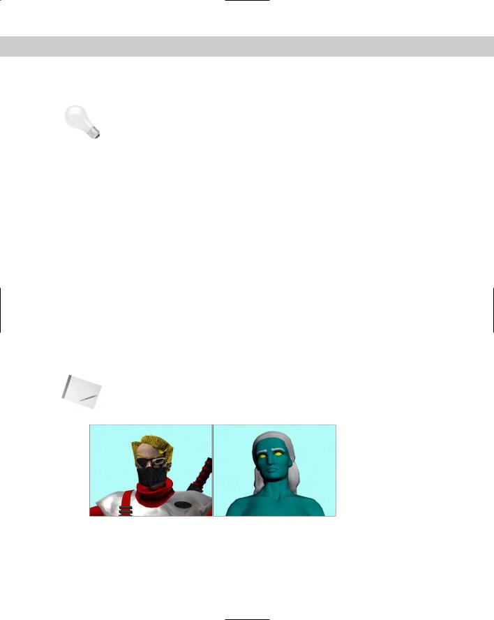
Figure 34-1 shows two good examples. The ninja warrior on the left doesn’t need the details of a mouth or teeth because they are hidden behind his mask. In fact, if you were to remove his mask, the model would leave a large gaping hole. The Greek woman statue model on the right includes many necessary details including fingernails, toes, a bellybutton, and, uh, well, uh, other details.
Note You can actually find these two character models on the CD-ROM at the back of the book, compliments of Viewpoint Datalabs.
Figure 34-1: These two characters have details modeled where needed.

Chapter 34 Character Modeling 859
Building Bodies
Although this section sounds like an advertisement for the local gym, it actually deals with building a whole different set of muscles. But if you’re not careful, they could turn out really ugly. The first task in character modeling is to understand your character and its body structure. The structure defines how the character moves, which aids in the development of its personality.
|
Defining a structure |
|
Before you jump headlong into creating ear folds or modeling a kneecap, you need to develop |
|
a structure for your character. This involves many of the mundane tasks that don’t seem very |
|
important, but if you don’t do them up front, they can be much more difficult later on and |
|
they’ll really help when you begin to animate your characters. |
Note |
If you’re interested in getting some help with modeling human figures (and many animals), |
|
Curious Labs has created a program called Poser whose goal is to model and animate |
|
human figures. The software makes it easy to create, modify, and pose realistic human fig- |
|
ures with all the details and to export them so they can be imported into Max. |
|
Naming objects |
|
When you create new body parts, be sure to name each one. Nothing is more frustrating than |
|
trying to locate a specific body part from a sea of cylinder and sphere objects. If you’ve created |
|
lots of different body parts that you need to name, you can use the Schematic View window to |
|
quickly locate and name them. |
|
If your character is going to have lots of body parts, you’ll want to have a naming convention |
|
that makes finding objects easier. Then stick with it, and be consistent. For example, a human |
|
figure will have two forearm objects, so you’ll want to identify them as right forearm and left |
|
forearm, but if you call one “right forearm” and the other “forearm on the left,” then finding one |
|
or the other will be tricky when you start looking for them in the Select Objects dialog box. |
Tip |
I like to end body part names with a single letter that tells me which side it is on, such as |
|
“hand_r.” By doing this, like body parts are listed together when alphabetized in the Select |
|
Objects dialog box, rather than listing all the objects on the right side of the body together. |
|
Tutorial: Creating a primitive man |
|
When creating a character out of primitives, you don’t need to pay attention to detail, but |
|
the keys to remember are naming the parts correctly and aligning the parts with the correct |
|
symmetry. |
|
To model a simple character from primitives, follow these steps: |
1.Select Create Standard Primitives Box, enable the Cube option, and then drag in the Front viewport to create a cube object. Name this object pelvis.
2.Click the Box button in the command panel, and drag in the Front viewport to create a Box object above the pelvis and a little wider and tall. Name this object chest.
860 Part VIII Character Animation
3.Click the Cylinder button, and drag in the Top viewport to create a cylinder object. Select and move this object until it is above the chest object. Name this object neck.
4.Click the Sphere button, and drag in the Top viewport to create a sphere. Select and move this object above the neck object. Name this object head.
5.Select the head, neck, and chest objects, choose Tools Align (Alt+A), and click the pelvis object. In the Align Selection dialog box, select to align the Centers of the X and Z axes and click OK.
This aligns all these objects.
6.Click the Cylinder button, and drag in the Left viewport to create a cylinder. Select and move this object in the Front viewport so that it extends outward from the chest object. Name this object upper_arm_r.
7.With the Select and Move tool, hold down the Shift key and drag the upper arm object to the left in the Front viewport. Then scale down this object and name it lower_arm_r. In the Clone Options dialog box, you can specify that changes made to one arm will also be made to the Instance.
8.Click the Sphere button, create a sphere in the Front viewport at the end of the lower arm, and position it to connect to the lower arm. Name this object hand_r.
9.Select the upper and lower arm objects, choose Tools Align (Alt+A), and click the hand object. In the Align Selection dialog box, select to align the Centers of the Y and Z axes and click OK.
10.Select all the objects that make up the right arm, and choose Tools Mirror. In the Mirror dialog box that appears, select the X-axis mirror with an Offset value enough to move it to the other side of the chest. Then select the Instance option, enable the Mirror IK Limits option, and click OK. Then rename the mirrored arm parts to designate the left side.
11.Select all the parts in the left arm, and hold down the Shift key while rotating 90 degrees clockwise. In the Clone Options dialog box, select the Copy option and click OK. Then position these cloned objects as the right leg below the pelvis. Then rename all the new parts accordingly.
12.Select all the parts of the right leg, hold down the Shift key, and drag to the right in the Front viewport to create the left leg. Then name the left leg parts.
13.Complete a last scan of the character to make sure that all objects overlap their adjacent body part.
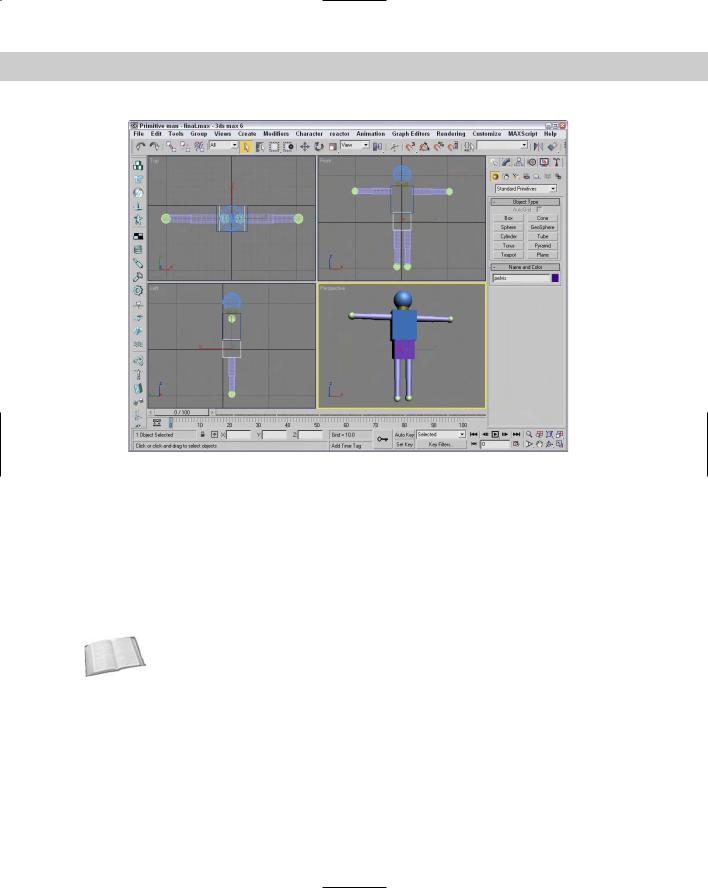
Figure 34-2 shows the primitive character correctly aligned.
Positioning pivots
The next step to check is to make sure that the pivot points for the object is in the right place. For arms, legs, feet, and hands, you want the pivot located at the center of the joint where the body part connects with its parent. For example, the pivot for the forearm object should be located at the elbow. This allows the forearm to rotate about its pivot. If the pivot were located at the center of the object, then the object would separate from its parent when the object is rotated (which sounds pretty painful).
Chapter 34 Character Modeling 861
Figure 34-2: A character created quickly out of primitive objects lets you align and name all the various parts.
Establishing hierarchy
Okay, now let’s sing, “the knee bone’s connected to the shin bone.” All structures have a structure (unless you’re modeling an amorphous blob, in which case you should proceed directly to the Flex modifier).
As you build separate body parts, you should remember how they are suppose to link to the surrounding body parts. This task is another one that the Schematic View can really help with, because connecting nodes can be easier than connecting actual geometries. Using the Select and Link tool on the main toolbar, you can drag from the child object to its parent.
Cross- |
The Schematic View window is discussed in Chapter 9, “Working with the Schematic View.” |
Reference |
|
The big question is which body part is the root (or parent to all the other body parts), or does the head really rule the heart? It really depends on your character and its structure, but you’ll want to make the root a body part that is easy to select and position because all the other body parts move along with it. You also want a body part that is at the center of the motion, so you should work backward from the fingers, which are controlled by the hand, which is controlled by the forearm, which is controlled by the upper arm, which is controlled by the shoulder, which is controlled by the chest, which is connected to the neck and the pelvis.
Although you may want, incorrectly, to make the head the root object, the pelvis is actually a better root because it is central to the legs and the chest, which controls the arms and neck.
862 Part VIII Character Animation
Tutorial: Creating a character’s structure
If you’ve correctly named all the various body parts, then the Schematic View window makes linking up the various parts into a structure easy. Before we do that, though, we still need to check the pivot points.
To create a character structure from linking body parts, follow these steps:
1.Open the Linked primitive man.max file from the Chap 34 directory on the CD-ROM. This file is the same as the one with which we concluded the preceding tutorial.
2.Click the various body parts, and notice where the Transform Gizmo is located. This marks the pivot point for the selection. If you can’t see the Transform Gizmo, select the Views Show Transform Gizmo menu command (or press the X key). For this character, all cylinders are correct, but you want to move the pivot points for all sphere primitives.
3.To move a pivot point, open the Hierarchy panel, click the Pivot button, click the Affect Pivot Only button, and move the pivot using the Select and Move (W) tool. For each sphere object, move the pivot point toward the body part that it overlaps. Be sure to click the Affect Pivot Only button again to exit this mode when you are finished.
4.To link all body parts, select Graph Editors New Schematic View to open the Schematic View window. Select the Edit Connect menu command (or press the C key). Then drag from each child object to its parent. As the nodes are connected, you can click the Zoom Extents button in the lower-right corner to more clearly see the node names.
The Schematic View automatically positions the various nodes in a hierarchical structure.
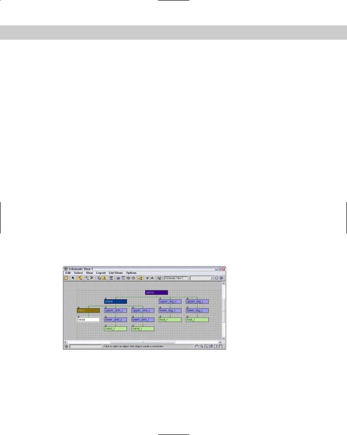
With all the body parts connected, they now move together when the pelvis object is selected and moved. Figure 34-3 shows the resulting hierarchy in the Schematic View.
Figure 34-3: The Schematic View window makes connecting objects easy.

Chapter 34 Character Modeling 863
|
Modeling techniques |
|
Max includes a number of different ways to model characters, including meshes, patches, |
|
and NURBS. Each of these methods has its strengths and weakness, but you should use the |
|
method with which you are most comfortable. For example, I have more experience modeling |
|
with meshes, specifically Editable Poly objects, but I know other modelers who are more |
|
comfortable with NURBS. Our models are comparable, but the difference is the time each of |
|
us spends to create our models. |
|
Starting with primitives |
|
One method to character modeling (that we’ve already jumped into with the first two tutori- |
|
als) is to start with primitive objects that are close to the end object and then to modify them |
|
as needed to create the final character before converting them to Editable Mesh or Editable |
|
Poly objects. This is particularly easy to do if you’re modeling a cartoon-like character. |
Tip |
When starting with sphere objects, you may find the GeoSphere objects much easier to work |
|
with than the normal sphere because of its regularity and equally spaced faces. |
|
Modeling subobjects |
|
After the rough character parts have been converted to an Editable object, you can work with |
|
its subobjects to mold the body part into something that looks closer to what you want. |
|
When working on an individual body part, you may find using the Tools Isolate Selection |
|
(Alt+Q) menu command easier, or you may want to use the Tools Display Floater to hide all |
|
objects except for the one that you’re working on. |
|
You can then select and move subobjects to get your body part closer to what you want it to |
|
be. Start by moving vertices. For example, as you model the chest object, you’ll probably |
|
want to move the vertices around the shoulders out farther and contract them around the |
|
mid-section. |
Tip |
As you begin to refine the mesh and move smaller subobject selections, you’ll find the Soft |
|
Selection feature very helpful because it doesn’t require to you select all the subobjects, just |
|
the center subobjects, causing the surrounding subobjects to move with it. |
|
Increasing resolution |
|
After you have a rough outline shape of the body part completed, you’ll get to a point where |
|
you need more resolution. You can increase the resolution of the object you’re working on in |
|
several ways. If you’re using Editable Mesh or Poly objects, you can select individual faces |
|
and increase the number of faces, using a Tessellate function. |
|
Another way to increase resolution within a specific area is with the Cut tool. Using this tool, |
|
you can create an edge exactly where you want one, and a new vertex is placed at every inter- |
|
secting line. |
|
When you start to subdivide an object, be sure to subdivide the entire object to a sufficient |
|
level before subdividing certain sections. You don’t want to be left with a single edge that has |
|
numerous faces on one side and a single face on the other. This causes lots of small triangles |
|
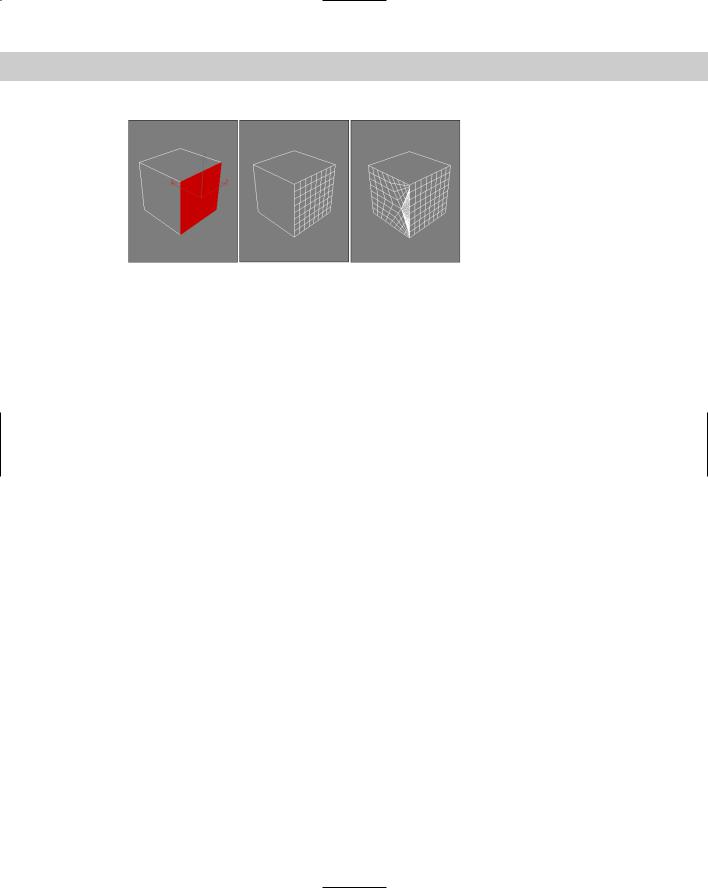
if you ever need to subdivide the large face, as shown in Figure 34-4. |
864 Part VIII Character Animation
Figure 34-4: Avoid having to subdivide a single large face that shares an edge with many faces.
Tutorial: Creating chest muscles
As a quick example of how subobjects can be manipulated to form the details for the body parts, we work on the pectoral muscles of the chest by moving vertices.
To create some chest muscles using the Vertex subobject mode, follow these steps:
1.Open the Chest muscles.max file from the Chap 34 directory on the CD-ROM. This file includes the primitive man model that we worked on earlier.
2.Select the chest object, and open the Display Floater with the Tools Display Floater menu command. Then click the Unselected button in the Hide column, and press the Z key to zoom in on the chest object in all viewports.
3.Right-click the chest object, and select Convert To Editable Poly in the pop-up quadmenu. Then click Vertex Subobject mode in the Selection rollout to see all the vertices that make up this primitive Box object.
4.Select the vertices in the lower-left corner of the Front viewport, and drag them to the right slightly. Then select the lower-right corner vertices, and drag them to the left to form an inverted trapezoid. Then in the Top viewport, select the top two inner vertices and drag them down. Then drag the bottom two inner vertices in the Top viewport, and drag them up.
This tightens the object around the waist, but leaves it broader in the shoulders.
5.Click the Polygon subobject mode button in the Selection rollout, and drag over the entire object to select all its polygons. Then click the Tessellate button three times to increase the overall resolution of the object.
6.In the third row of polygons on the front face, hold down the Ctrl key while clicking the first, fourth, fifth, and eighth polygon faces to select them and then click on the Tessellate button again. This adds more resolution to the bottom of the pectoral muscle. Repeat this step again, selecting the polygons that lie in the path of the muscle boundary.
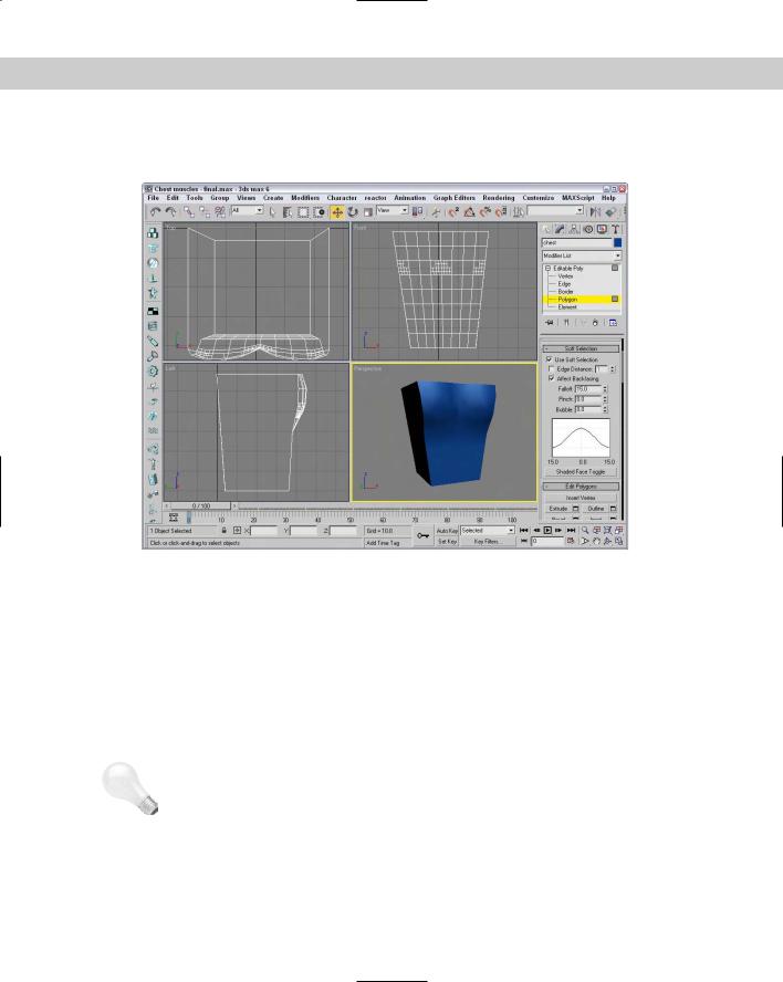
7.Hold down the Ctrl key, and select the second, third, sixth, and seventh polygons in the second row. These polygons are at the center of the pectoral muscle. In the Soft Selection rollout, click the Use Soft Selection option and set the Falloff value to 15.0. To see which polygons are affected, click the Shaded Face Toggle button. Then drag to the right in the Left viewport to pull the selected faces outward.
Chapter 34 Character Modeling 865
Figure 34-5 shows the resulting muscles. From here, you can continue to apply the same technique to add stomach muscles and muscles around the shoulders and back.
Figure 34-5: Muscles can be created by editing selected subobjects with Soft Selection enabled.
|
Smoothing body parts |
|
After you’ve added all the necessary details, you can work on smoothing the edges of your |
|
primitive objects. You can do this in several ways. If you are dealing with a particularly hard |
|
edge, you can start by selecting the edge in Edge subobject mode and applying a Chamfer. |
|
This replaces the hard edge with a face and eases any smoothing operations for the object. |
|
Another technique is to use the MSmooth feature (available for Editable Poly objects) or the |
|
MSmooth modifier. Be aware that this feature may move your vertices aggressively if there |
|
isn’t enough resolution. It can also increase your total number of polygons exponentially, |
|
resulting in huge models. |
Tip |
If you find that a mesh smooth operation is slowing down your system, try collapsing your |
|
model to increase the speed again. But you should use the Edit Hold (Alt+Ctrl+H) menu |
|
command before doing so, in case you ever need to revisit the mesh smooth. |
Yet a third smoothing technique (and perhaps the best) is found in the in the Subdivision Surface rollout for Editable Poly objects–NURMS Subdivision. By enabling this option and setting the Iterations to a reasonable number, you get the smoothing you want.

866 Part VIII Character Animation
Creating smooth joints
After you have all the various body parts looking good, the next trick comes in trying to join them so they look seamless. You’ll find that the MSmooth operation is helpful, but you should try some other techniques first.
For the best smoothing, you need to combine body parts so the polygon edges are shared between the different body parts. Do not overlap objects, or you’ll see some funny artifacts along the border. You may notice that I break this rule frequently in many examples (look closely at the snowman example in various chapters), but when modeling body parts where smoothing counts, you should watch this carefully.
Another way of modeling characters is to create the various body parts as separate objects that are positioned close to each other without quite touching. Some animators like this approach because it doesn’t rely on a skin or bones.
The process for combining separate body parts can be gruesome, so if you have a weak stomach, you may want to get a drink of water first. The process is to cut a hole in both body parts and then connect the open borders. This is why Border subobject mode for Editable Polys is so helpful. Creating holes in geometry is easy. You just need to select the polygon faces where the hole should be and delete them. Prior to deleting a close approximation of the hole, use the Cut tool to mark where the hole should go; selecting the subobject faces is then easy.
After a hole exists in your body part, use Border subobject mode to select the edge that surrounds the hole and use the Extrude feature to create a set of polygons that reach out toward the body part that needs to be attached. These extra polygons help as you begin to smooth the joint between the two parts.
With holes in both body parts, you can connect them using the Create tool to manually create new faces that link the two objects. But a faster way is to use the Connect compound object.
Tutorial: Attaching an arm to the chest
In this tutorial, you perform some surgery by cutting and attaching objects, so if you’re not a surgeon wannabe, think of this as an experiment in wood shop.
To attach an arm to a chest part, follow these steps:
1.Open the Attach arm.max file from the Chap 34 directory on the CD-ROM.
This file includes the modified chest object from the preceding tutorial, with all the body parts hidden except the chest and one arm.
2.Select the chest object, and enable the Polygon subobject mode. Then click the Cut button, and cut lines in the Left viewport that roughly follow the blue cross section of the arm. Right-click when you’ve made it around the circle to exit cut mode, and click the Cut button again to disable it.
3.Enable the Ignore Backfacing option in the Selection rollout, press and hold the Ctrl key, and click all the polygons within the circle. Press the Delete key to delete all these polygons, and answer Yes to the dialog box that asks if you wish to delete the isolated vertices.
4.Click the Border icon in the Selection rollout to enable Border subobject mode, and select the border around the open hole. Then click the setting icon for the Extrude feature, enter an Extrusion Height value of 2.0 and an Extrusion Base Width value of 3.0, and click OK.

Chapter 34 Character Modeling 867
5.Disable Border subobject mode, and then move the cylinder away from the chest object so you can see the polygon face closest to the chest. Select the chest object, click the Attach button, and then click the arm object to attach it to the chest object. This automatically converts the Cylinder object to an Editable Poly object. Then in Polygon subobject mode, select and delete the end of the cylinder closest to the chest object.
6.With the two open holes facing one another, select Create Compound Connect to connect the two body parts. A new row of polygons is created, connecting the two parts. Right-click the object, and select Convert To Editable Poly to convert it back to an Editable Poly object for more editing.
7.In Polygon subobject mode, select all the newly created polygons surrounding the joint and click the MSmooth button to smooth the joint.
Figure 34-6 shows the completed joint.
Figure 34-6: A smooth joint without any seams renders well.
Using BlobMesh objects
BlobMesh objects can also be used to model muscles. Because BlobMeshes run together, they form a smooth surface when placed next to one another, similar to the way that muscles behave.

868 Part VIII Character Animation
To use BlobMeshes, position them close to one another in an arrangement that is similar to the muscle structure. Then select one of the BlobMeshes, and in the Modify panel, Pick or Add the other BlobMeshes to the group. This combines them into a single object that you can then convert to an Editable Poly or an Editable Patch object for more editing.
Working with hands and feet
Hands and feet are just small versions of the body, but you can use many of the same techniques. When working with these objects, be aware that a single hand can double or triple the number of polygons in the model. Many models avoid showing hands or feet by using simple cartoon-looking hands or gloves.
Modeling clothing
Clothing items can also be used to hide some details, but they also have details of their own. If you want to animate the movement of your clothing, reactor includes support for simulating the movement of cloth.
Cross- |
You can learn more about reactor in Chapter 40, “Animating with reactor.” |
Reference |
|
Creating hair
Of all the details of the body, hair can be the toughest and most computationally expensive. Although Max includes several ways to cheat when making hair, it still does not include any robust method for creating and managing hair outside of the available plug-in.
Note |
The plug-ins available for Max that deal with hair are Shag: Fur and Shag: Hair. These plug-ins |
|
do an excellent job, and we can only hope that they are incorporated into Max someday. |
One way to cheat creating hair is with the Compound Scatter object. By creating a cylinder to represent a single hair strand and using the head object as its Distribution Object, you can quickly add many hair objects to the head. Be aware that the Scatter object is connected at its pivot point, so you want to make sure that it is aligned correctly before creating the Scatter object. Also, if you select several subobject faces on your head object before creating the Scatter object, you can select to apply the hairs only to the selected subobject faces, thereby targeting where the hair is.
After hair is created, you can control its movement using reactor’s Rope Collection. This makes the hair flow and move around the head realistically. Another option is to use the Flex modifier to make the hair springy as the head moves about.
Tutorial: Adding hair to a head
For this example, we use the Scatter compound object to add some hair to a simple sphere object.
To add some hair to a sphere object using the Scatter compound object, follow these steps:
Chapter 34 Character Modeling 869
1.Select Create Standard Primitives GeoSphere, and drag in the Front viewport to create the object. Set the Segments value to 12 to add sufficient resolution to the sphere.
2.Right-click the sphere, and select Convert To Editable Poly to convert the sphere. Then select Polygon subobject mode, and drag over a quarter of the head to select the polygons where the hair will be. Make sure that the Ignore Backfacing option in the Selection rollout is disabled to get both sides of the head.
3.Select Create Standard Primitives Cylinder, and drag in the Front viewport to create a simple cylinder object. Set its Radius to 0.2 and its Height to 30.
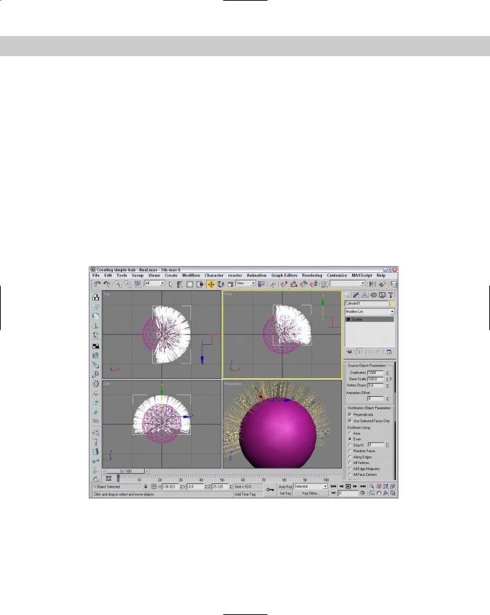
4.With the Cylinder selected, select Create Compound Scatter. Then click the Pick Distribution Object button, and select the GeoSphere object with the Instance option selected. In the Scatter Object rollout, enable the Use Selected Faces Only option and set the Duplicates number to 1000. Then in the Display rollout, enable the Hide Distribution Object option.
Figure 34-7 shows the sphere with its hair sticking straight out. You can use some modifiers to then control the hair’s movement. Be aware that with a thousand cylinders to keep track of, it slows your viewport refresh dramatically.
Figure 34-7: Simple hair (actually, it looks more like fuzz) can be created with the Scatter compound object.