

- •Preface
- •About This Book
- •Acknowledgments
- •Contents at a Glance
- •Contents
- •Relaxing at the Beach
- •Dressing the Scene
- •Animating Motion
- •Rendering the Final Animation
- •Summary
- •The Interface Elements
- •Using the Menus
- •Using the Toolbars
- •Using the Viewports
- •Using the Command Panel
- •Using the Lower Interface Bar Controls
- •Interacting with the Interface
- •Getting Help
- •Summary
- •Understanding 3D Space
- •Using the Viewport Navigation Controls
- •Configuring the Viewports
- •Working with Viewport Backgrounds
- •Summary
- •Working with Max Scene Files
- •Setting File Preferences
- •Importing and Exporting
- •Referencing External Objects
- •Using the File Utilities
- •Accessing File Information
- •Summary
- •Customizing Modify and Utility Panel Buttons
- •Working with Custom Interfaces
- •Configuring Paths
- •Selecting System Units
- •Setting Preferences
- •Summary
- •Creating Primitive Objects
- •Exploring the Primitive Object Types
- •Summary
- •Selecting Objects
- •Setting Object Properties
- •Hiding and Freezing Objects
- •Using Layers
- •Summary
- •Cloning Objects
- •Understanding Cloning Options
- •Mirroring Objects
- •Cloning over Time
- •Spacing Cloned Objects
- •Creating Arrays of Objects
- •Summary
- •Working with Groups
- •Building Assemblies
- •Building Links between Objects
- •Displaying Links and Hierarchies
- •Working with Linked Objects
- •Summary
- •Using the Schematic View Window
- •Working with Hierarchies
- •Setting Schematic View Preferences
- •Using List Views
- •Summary
- •Working with the Transformation Tools
- •Using Pivot Points
- •Using the Align Commands
- •Using Grids
- •Using Snap Options
- •Summary
- •Exploring the Modifier Stack
- •Exploring Modifier Types
- •Summary
- •Exploring the Modeling Types
- •Working with Subobjects
- •Modeling Helpers
- •Summary
- •Drawing in 2D
- •Editing Splines
- •Using Spline Modifiers
- •Summary
- •Creating Editable Mesh and Poly Objects
- •Editing Mesh Objects
- •Editing Poly Objects
- •Using Mesh Editing Modifiers
- •Summary
- •Introducing Patch Grids
- •Editing Patches
- •Using Modifiers on Patch Objects
- •Summary
- •Creating NURBS Curves and Surfaces
- •Editing NURBS
- •Working with NURBS
- •Summary
- •Morphing Objects
- •Creating Conform Objects
- •Creating a ShapeMerge Object
- •Creating a Terrain Object
- •Using the Mesher Object
- •Working with BlobMesh Objects
- •Creating a Scatter Object
- •Creating Connect Objects
- •Modeling with Boolean Objects
- •Creating a Loft Object
- •Summary
- •Understanding the Various Particle Systems
- •Creating a Particle System
- •Using the Spray and Snow Particle Systems
- •Using the Super Spray Particle System
- •Using the Blizzard Particle System
- •Using the PArray Particle System
- •Using the PCloud Particle System
- •Using Particle System Maps
- •Controlling Particles with Particle Flow
- •Summary
- •Understanding Material Properties
- •Working with the Material Editor
- •Using the Material/Map Browser
- •Using the Material/Map Navigator
- •Summary
- •Using the Standard Material
- •Using Shading Types
- •Accessing Other Parameters
- •Using External Tools
- •Summary
- •Using Compound Materials
- •Using Raytrace Materials
- •Using the Matte/Shadow Material
- •Using the DirectX 9 Shader
- •Applying Multiple Materials
- •Material Modifiers
- •Summary
- •Understanding Maps
- •Understanding Material Map Types
- •Using the Maps Rollout
- •Using the Map Path Utility
- •Using Map Instances
- •Summary
- •Mapping Modifiers
- •Using the Unwrap UVW modifier
- •Summary
- •Working with Cameras
- •Setting Camera Parameters
- •Summary
- •Using the Camera Tracker Utility
- •Summary
- •Using Multi-Pass Cameras
- •Creating Multi-Pass Camera Effects
- •Summary
- •Understanding the Basics of Lighting
- •Getting to Know the Light Types
- •Creating and Positioning Light Objects
- •Viewing a Scene from a Light
- •Altering Light Parameters
- •Working with Photometric Lights
- •Using the Sunlight and Daylight Systems
- •Using Volume Lights
- •Summary
- •Selecting Advanced Lighting
- •Using Local Advanced Lighting Settings
- •Tutorial: Excluding objects from light tracing
- •Summary
- •Understanding Radiosity
- •Using Local and Global Advanced Lighting Settings
- •Working with Advanced Lighting Materials
- •Using Lighting Analysis
- •Summary
- •Using the Time Controls
- •Working with Keys
- •Using the Track Bar
- •Viewing and Editing Key Values
- •Using the Motion Panel
- •Using Ghosting
- •Animating Objects
- •Working with Previews
- •Wiring Parameters
- •Animation Modifiers
- •Summary
- •Understanding Controller Types
- •Assigning Controllers
- •Setting Default Controllers
- •Examining the Various Controllers
- •Summary
- •Working with Expressions in Spinners
- •Understanding the Expression Controller Interface
- •Understanding Expression Elements
- •Using Expression Controllers
- •Summary
- •Learning the Track View Interface
- •Working with Keys
- •Editing Time
- •Editing Curves
- •Filtering Tracks
- •Working with Controllers
- •Synchronizing to a Sound Track
- •Summary
- •Understanding Your Character
- •Building Bodies
- •Summary
- •Building a Bones System
- •Using the Bone Tools
- •Using the Skin Modifier
- •Summary
- •Creating Characters
- •Working with Characters
- •Using Character Animation Techniques
- •Summary
- •Forward versus Inverse Kinematics
- •Creating an Inverse Kinematics System
- •Using the Various Inverse Kinematics Methods
- •Summary
- •Creating and Binding Space Warps
- •Understanding Space Warp Types
- •Combining Particle Systems with Space Warps
- •Summary
- •Understanding Dynamics
- •Using Dynamic Objects
- •Defining Dynamic Material Properties
- •Using Dynamic Space Warps
- •Using the Dynamics Utility
- •Using the Flex Modifier
- •Summary
- •Using reactor
- •Using reactor Collections
- •Creating reactor Objects
- •Calculating and Previewing a Simulation
- •Constraining Objects
- •reactor Troubleshooting
- •Summary
- •Understanding the Max Renderers
- •Previewing with ActiveShade
- •Render Parameters
- •Rendering Preferences
- •Creating VUE Files
- •Using the Rendered Frame Window
- •Using the RAM Player
- •Reviewing the Render Types
- •Using Command-Line Rendering
- •Creating Panoramic Images
- •Getting Printer Help
- •Creating an Environment
- •Summary
- •Creating Atmospheric Effects
- •Using the Fire Effect
- •Using the Fog Effect
- •Summary
- •Using Render Elements
- •Adding Render Effects
- •Creating Lens Effects
- •Using Other Render Effects
- •Summary
- •Using Raytrace Materials
- •Using a Raytrace Map
- •Enabling mental ray
- •Summary
- •Understanding Network Rendering
- •Network Requirements
- •Setting up a Network Rendering System
- •Starting the Network Rendering System
- •Configuring the Network Manager and Servers
- •Logging Errors
- •Using the Monitor
- •Setting up Batch Rendering
- •Summary
- •Compositing with Photoshop
- •Video Editing with Premiere
- •Video Compositing with After Effects
- •Introducing Combustion
- •Using Other Compositing Solutions
- •Summary
- •Completing Post-Production with the Video Post Interface
- •Working with Sequences
- •Adding and Editing Events
- •Working with Ranges
- •Working with Lens Effects Filters
- •Summary
- •What Is MAXScript?
- •MAXScript Tools
- •Setting MAXScript Preferences
- •Types of Scripts
- •Writing Your Own MAXScripts
- •Learning the Visual MAXScript Editor Interface
- •Laying Out a Rollout
- •Summary
- •Working with Plug-Ins
- •Locating Plug-Ins
- •Summary
- •Low-Res Modeling
- •Using Channels
- •Using Vertex Colors
- •Rendering to a Texture
- •Summary
- •Max and Architecture
- •Using AEC Objects
- •Using Architectural materials
- •Summary
- •Tutorial: Creating Icy Geometry with BlobMesh
- •Tutorial: Using Caustic Photons to Create a Disco Ball
- •Summary
- •mental ray Rendering System
- •Particle Flow
- •reactor 2.0
- •Schematic View
- •BlobMesh
- •Spline and Patch Features
- •Import and Export
- •Shell Modifier
- •Vertex Paint and Channel Info
- •Architectural Primitives and Materials
- •Minor Improvements
- •Choosing an Operating System
- •Hardware Requirements
- •Installing 3ds max 6
- •Authorizing the Software
- •Setting the Display Driver
- •Updating Max
- •Moving Max to Another Computer
- •Using Keyboard Shortcuts
- •Using the Hotkey Map
- •Main Interface Shortcuts
- •Dialog Box Shortcuts
- •Miscellaneous Shortcuts
- •System Requirements
- •Using the CDs with Windows
- •What’s on the CDs
- •Troubleshooting
- •Index
870 Part VIII Character Animation
Summary
Building characters is a process that requires several different steps, and this chapter has presented a single approach. Other methods exist, and you should find one that works for you. This chapter covered the following topics:
How to create a character’s structure
A modeling approach using subobjects and smoothing
A method for connecting body parts
A simple way to create hair
This knowledge now prepares you to rig the character with bones that can be used to animate it.
|
|
|

Rigging Characters
Alinked hierarchy attaches, or links, one object to another and makes transforming the attached object by moving the
one it is linked to possible. The arm is a classic example of a linked hierarchy — when the shoulder rotates, so do the elbow, wrist, and fingers. Establishing linked hierarchies can make moving, positioning, and animating many objects easy.
A bones system is a unique case of a linked hierarchy that has a specific structure. You can create a structure of bones from an existing hierarchy, or you can create a bones system and attach objects to it. A key advantage of a bones system is that you can use IK Solvers to manipulate and animate the structure.
After you’ve created a system of bones, you can cover the bones with objects that have the Skin modifier applied. This modifier lets the covering object move and bend with the bone structure underneath. The process of attaching a model to a bones systems and skin is called rigging.
Building a Bones System
In some instances, establishing a hierarchy of objects before linking objects is easier. By building the hierarchy first, you can be sure of the links between objects. One way to build this hierarchy is to use a bones system. A bones system consists of many bone objects that are linked together. These bone objects are normally not rendered, but you can set them to be renderable, like splines. You can also assign an IK Solver to the bones system for controlling their motion.
To create a bones system, select Create Systems Bones IK Chain and click in a viewport to create a root bone, click a short distance away to create another bone, and repeat this a few more times. Each subsequent click creates another bone linked to the previous one. When you’re finished adding bones, right-click to exit bone creation mode. In this manner, you can create a long chain of bone objects all linked together.
These bones are actually linked joints. Moving one bone pulls its neighbors in the chain along with it. Bones can also be rotated, scaled, and stretched. Scaling a bones system affects the distance between the bones.
To branch the hierarchy of bones, simply click the bone where you want the branch to start while still in bone creation mode. A new
35C H A P T E R
In This Chapter
Building a bones system
Setting bone parameters and IK Solvers
Making linked objects into bones system
Using the Skin modifier
872 Part VIII Character Animation
branching bone is created automatically. Click the Bones button again to create a new bone. Then continue to click to add new bones to the branch.
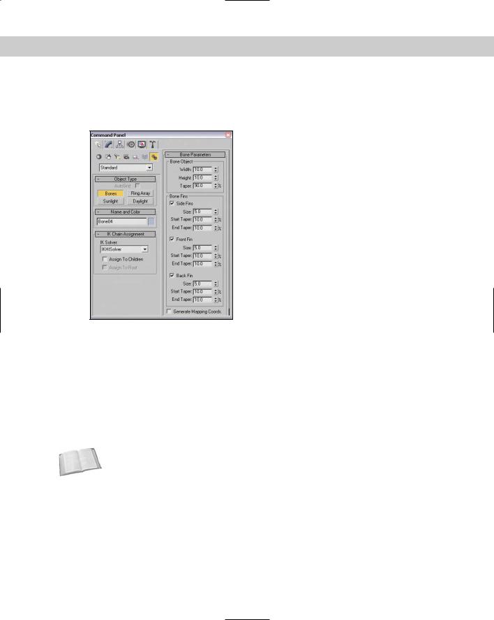
Figure 35-1 shows the rollouts that are available for creating bones.
Figure 35-1: The Bone rollouts lets you specify which bones get assigned an
IK Controller.
Assigning an IK Solver
In the IK Chain Assignment rollout, you can select from four different IK Solvers: History Dependent, IKHISolver, IKLimb, and SplineIK Solver. You can assign each of these solver types to children and to the root bone using the available options. You need to select both the Assign to Children and the Assign to Root options to assign the IK Controller to all bones in the system. If the Assign to Children option is deselected, then the Assign to Root option is disabled.
Cross- |
Chapter 37, “Using Inverse Kinematics,” presents details on each of these IK Solvers. |
Reference |
|
Setting bone parameters
The Bone Parameters rollout includes parameters for setting the size of each individual bone, including its Width and Height. You can also set the percentage of Taper applied to the bone.
Fins can be displayed on the front, back, and/or sides of each bone. For each fin, you can specify its size and start and end taper values. Including fins on your bones makes correctly positioning and rotating the bone objects easier. Figure 35-2 shows a simple bones system containing two bones. The first bone has fins.

Chapter 35 Rigging Characters 873
Figure 35-2: This bone includes fins that make understanding its orientation easier.
At the bottom of the Bone Parameters rollout is an option to Generate Mapping Coordinates. Bones are renderable objects, so this option lets you apply texture maps to them.
Tutorial: Making a simple puppet using bones
Starting simply, a good example is a puppet. The bones system for the puppet can be built first. If you specify the IK Solver before building the bones, then you’re ready to animate the puppet after it is finished.
To create a simple puppet out of bones, follow these steps:
1.Select Create Systems Bones IK Chain and in the IK Chain Assignment rollout, select IK Limb from the IK Solver drop-down list. To be able to see the orientation of each bone, enable the Side Fins.
2.In the Front viewport, click where you want the head bone to start and click again where the neck will be, then continue to click to form the spine, pelvis, right thigh, right lower leg, and foot bones. Then right-click to end the bones chain.
3.While still in Bones mode, click the pelvis bone in the Front viewport and drag to the left to form the left thigh bone. Continue to click to form the left lower leg and left foot bones. Right-click to end the chain.
4.Form the right arm bones by clicking the head bone and clicking consecutively to form the right upper arm, right lower arm, and hand bones. Right-click to end the chain.